AFJ432200Analogue Scanning Receiver
ICOM Incorporated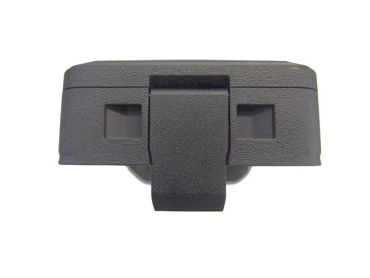
Click to zoom
Application Details
- Equipment Class
- CSR - Scanning Receiver
- Date of Grant
- Mar 25, 2024
- Application Purpose
- Original Equipment
- Date of Application
- Mar 25, 2024
- Equipment Note
- Analogue Scanning Receiver
- Frequency Range
- 108.00000000 - 500.00000000
- Company
- ICOM Incorporated
- Country
- Japan
Documents & Files
Document Text
Text extracted from the exhibit documents filed with the FCC. Open a document above to read the original.
Users Manual
BASIC MANUAL COMMUNICATIONS RECEIVER |R15 This device complies with part 15 of the FCC Rules. Operation is subject to the condition that this device does not cause harmful interference. WARNING: MODIFICATION OF THIS DEVICE TO RECEIVE CELLULAR RADIOTELEPHONE SERVICE SIGNALS IS PROHIBITED UNDER FCC RULES AND FEDERAL LAW. 1 BASIC MANUAL Thank you for choosing this Icom product. This product was designed and built with Icom’s state of the art technology and craftsmanship. With proper care, this product should provide you with years of trouble-free operation. ■Important READ ALL INSTRUCTIONS carefully and completely before using the receiver. SAVE THIS INSTRUCTION MANUAL — This instruction manual contains basic operating instructions for the IC-R15. For advanced operating instructions, see the Advanced manual for details. The Advanced manual can be downloaded from the following internet address: https://www.icomjapan.com/support/ ■Features zDualwatch function that can simultaneously receive and record two different bands or modes. zA USB connector for data transmission or battery charging zA microSD card slot that can accept different cards to backup settings, various memories, and so on. zBluetooth ® function that can connect to a Bluetooth ® device zMeets IPX7 requirements for waterproof protection (When the battery, the antenna, the [ ] jack cover, [USB] cover, and the [microSD] slot cover are attached) ■Explicit definitions WORDDEFINITION RDANGER! Personal death, serious injury or an explosion may occur. RWARNING! Personal injury, fire hazard or electric shock may occur. CAUTION Equipment damage may occur. NOTE Recommended for optimum use. No risk of personal injury, fire or electric shock. Icom is not responsible for the destruction, damage to, or performance of any Icom or non-Icom equipment, if the malfunction is because of: • Force majeure, including, but not limited to, fires, earthquakes, storms, floods, lightning, other natural disasters, disturbances, riots, war, or radioactive contamination. • The use of Icom receivers with any equipment that is not manufactured or approved by Icom. About weld lines This product’s surfaces may have streaks called “weld lines,” that occur during the molding process, and are not cracks or flaws. 2 1 7 4 10 15 18 2 8 13 5 11 16 3 9 14 6 12 17 BASIC MANUAL ■Precautions RDANGER! NEVER operate the receiver near unshielded electrical blasting caps or in an explosive atmosphere. This could cause an explosion and death. RWARNING! NEVER use or charge Icom battery packs with non-Icom receivers or non-Icom chargers. Only Icom battery packs are tested and approved for use with Icom receivers or charged with Icom chargers. Using third-party or counterfeit battery packs or chargers may cause smoke, fire, or cause the battery to burst. RWARNING! NEVER operate the equipment with earphones, a earphone, or other audio accessories at high volume levels. The continuous high volume operation may cause a ringing in your ears. If you experience the ringing in your ears, reduce a volume level or discontinue use. CAUTION: DO NOT operate the receiver while driving a vehicle. Safe driving requires your full attention— anything less could result in an accident. CAUTION: DO NOT short the terminals of the battery pack. Shorting may occur if the terminals touch metal objects such as a key, so be careful when placing the battery packs (or the receiver) in bags, and so on. Carry them so that shorting cannot occur with metal objects. Shorting may damage not only the battery pack, but also the receiver. CAUTION: DO NOT connect the receiver directly to a power source of more than the specified DC voltage or use reverse polarity. Otherwise this will damage the receiver. CAUTION: DO NOT operate the receiver unless the antenna, battery pack and covers are securely attached to the receiver and that the antenna and battery pack are dry before attachment. Exposing the inside to dust or water can damage the receiver. After exposure to water, clean the battery contacts thoroughly with fresh water and dry them completely to remove any water or salt residue. CAUTION: DO NOT use harsh solvents such as Benzine or alcohol when cleaning. This could damage the equipment surfaces. If the surface becomes dusty or dirty, wipe it clean with a soft, dry cloth. CAUTION: DO NOT place or leave the receiver in direct sunlight or in areas with temperatures below –20°C (–4 ̊F) or above +60°C (+140 ̊F). CAUTION: DO NOT change the internal settings of the equipment. This may reduce equipment performance and/or cause extensive and expensive damage to the equipment. The equipment warranty does not cover any problems caused by unauthorized internal adjustments. NEVER place in an insecure place to avoid inadvertent use by unauthorized persons. BE CAREFUL! The receiver meets IPX7* requirements for waterproof protection. However, once the receiver has been dropped, or the waterproof seal is cracked or damaged, the waterproof protection cannot be guaranteed. * Only when the BP-287, the antenna, [ ] jack cover, [USB] cover, and [microSD] slot cover are attached. Even when the receiver power is OFF, a slight current still flows in the circuits. Remove the battery pack or batteries from the receiver when not using it for a long time. Otherwise, the installed battery pack or batteries will become exhausted, and will need to be recharged or replaced. The LCD display may have cosmetic imperfections that appear as small dark or light spots. This is not a malfunction or defect, but a normal characteristic of LCD displays. 3 BASIC MANUAL ■Battery cautions Misuse of Li-ion batteries may result in the following hazards: smoke, fire, or the battery may rupture. Misuse can also cause damage to the battery or degradation of batteryʼs performance. RDANGER! NEVER incinerate used battery packs. Internal battery gas may cause an explosion. RDANGER! NEVER strike or otherwise impact the battery pack. Do not use the battery pack if it ha…
Text truncated - open the document above for the full version.
Attestation Statements
0 ICOM Federal Communications Commission Authorization and Evaluation Division 7435 Oakland Mills Road Columbia, MD 21046 USA Subject: Attestation Statements Part 2.911(d)(7) Filing Applicant: FCCID: Dear Sir/Madam: learn Inc AFJ432200, FRN: 0005855366 lcom Inc. 1-1-32 kamiminami Hirano-ku Osaka Japan. Phone: +81 66793-5301 Fax: +81 66793-0013 e-mail: [email protected] URL: https:/i\wvw.icomjapan.com' Date: March 18, 2024 learn Inc, ("the applicant'') certifies that, as of the date of the filing of the application, learn America Inc is our designated U.S. agent for service of process for the above referenced FCC ID. learn Inc accepts to maintain an agent for no less than one year after the grantee has terminated all marketing and importation or the conclusion of any Commission related proceeding involving the equipment. learn America Inc accepts, as of the date of the filing of the application, the obligation of the designated U.S. agent for service of process for the above referenced FCC ID. Designated U.S. Agent Information: • FRN 0001585587 • Name: • Address: • Contact Person: • Tel.: • Email: Sincerely, US Agent: Jim Backeland learn America Inc. President learn America Inc 12421 Willows Road NE Kirkland, WA 98034 Jim Backeland 425- 454-8155 [email protected] Applicant: Atsushi Tomiyama learn Inc General Manager of Quality Assurance Department
Attestation Statements
0 ICOM Federal Communications Commission Authorization and Evaluation Division 7 435 Oakland Mills Road Columbia, MD 21046 USA lcom Inc. 1-1-32 kamiminami Hirano-ku Osaka Japan. Phone: +81 6679�301 Fax: +81 66793-0013 e-mail: [email protected] URL: httpsJMWN.icomjapan.com' Date: March 18, 2024 Subject: Attestation Statements Parts 2.911(d)(5)(i) and 2.911(d)(5)(ii) Filing Applicant: Product: Model: FCCID: lcom Inc Scanning Receiver IC-R15 AFJ432200 Attestation for 47 CFR section 2.911(d)(5)(i) lcom Inc, ("the applicant'') certifies that the equipment for which authorization is sought is not "covered" equipment prohibited from receiving an equipment authorization pursuant to section 2. 903 of the FCC rules. Attestation for 47 CFR section 2.911(d)(5)(ii) lcom Inc, ("the applicant'') certifies that, as of the date of the filing of the application, the applicant is not identified on th e Covered List (as a specifically named entity or any of its subsidiaries or affiliates) as an entity producing "covered" equipment. Sincerely, l com Inc Atsushi Tomiyama General Manager of Quality Assurance Department
Cover Letter(s)
0 ICOM To Whom It May Concern Subject: Applicant: FCCID: Dear Sir/Madam: Confidentiality Letter lcom Incorporated AFJ432200 lcomlnc. 1-1-32 kamirrinami Hirano-ku Osaka Japan. Phone: +81 6679�301 Fax: +81 66793--0013 e-mail: [email protected] URL: https1MWW.icomjapan.cx,rn/ Date: March 18, 2024 The applicant would like to request the following documents submitted with this application for certification be withheld from public disclosure as per Section 0.457 & 0.459 of FCC Rules. Confidential 1. Operational Description 2. Bloc I< Diagram 3. Schematics 4. Parts List 5. Tuning Info 6. Internal Photos Short-Term Confidential for 120 days 6. Users Manual The above materials contain trade secrets and proprietary information not customarily released to the public. The public disclosure of these materials may be harmful to the applicant and provide unjustified benefits to its competitors. The applicant understands that pursuant to Section 0.457 of the Rules, disclosure of this application and all accompanying documentation shall not be made. Regards Atsushi Tomiyama General Manager of Quality Assurance Department
Cover Letter(s)
0 ICOM To Whom It May Concern Subject: Applicant: Product: Model: FCC ID: Authority to Act as an Agent learn Incorporated Scanning Receiver IC-R15 AFJ432200 lcom Inc. 1-1-32 kamirrinami Hirano-ku Osaka Japan. Phone: +81 66793-5301 Fax: +81 66793-0013 e-mail: [email protected] URL: https:/MWN.iromjapan.c:oov Date: March 18, 2024 Dear Sir/Madam, We hereby appoint Sharon Hoffman with TIMCO ENGINEERING, Inc. to act as our agent in preparation of this application for authorization of above equipment under F.C.C. Rules. We hereby certify that neither the application nor any party to the application is subject to a denial of Federal b enefits, that include FCC benefits, pursuant to Section 5301 of the Anti-Drug Abuse Act of 1988, 21 U.S. C. 862 because of a conviction for possession or distribution of a controlled substance. See 4 7 CRF 1.20 02(b) fo r the definition of a "party" for these purposes. We also certify that the information provided, property describe the device or system for which authorization is re quired. Best regards lc om Incorporated Atsushi Tomiyama General Manager of Quality Assurance Department
External Photos
Front Rear Top Bottom Left Right USB PORT Headset Port Micro SD Port
RF Exposure Info
Test Report# TR_12254-24_FCC 1.1310/ MPE_ Revision: 1 Te s t Report - FCC Par t 1.1310/ MPE Applicant: ICOM America, Inc. Approved for Release By: Signature: Name & Title: Bruno Clavier, General Manager Date of Signature 3/22/2024 This test report relates only to the items tested as identified and is not valid for any subsequent changes or modifications made to the equipment under test. 13146 NW 86 th Drive, Suite 400, Alachua, Florida 32615 (352) 472-5500 / [email protected] Page 2 of 10 This test report shall not be reproduced except in full without the written and signed permission of Timco Engineering Inc., a subsidiary of Industrial Inspection & Analysis, Inc. (IIA). Table of Contents 1. APPLICANT INFORMATION ........................................................................................................................................................................... 3 2. LOCATION OF TESTING ................................................................................................................................................................................. 3 2.1 TEST LABORATORY ...................................................................................................................................................................... 3 2.2 TESTING WAS PERFORMED, REVIEWED BY .................................................................................................................................... 4 3. TEST SAMPLE(S) (EUT/DUT) ........................................................................................................................................................................... 5 3.1 DESCRIPTION OF THE EUT .......................................................................................................................................................... 5 4. TEST METHODS & APPLICABLE REGULATORY LIMITS ............................................................................................................................ 6 4.1 TEST METHODS/STANDARDS/GUIDANCE: .................................................................................................................................... 6 4.1.1 FCC Limits for Maximum Permissible Exposure (MPE) .......................................................................................... 6 4.2 EQUATIONS ................................................................................................................................................................................ 7 5. RF EXPOSURE RESULTS .................................................................................................................................................................................. 8 6. HISTORY OF TEST REPORT CHANGES ........................................................................................................................................................ 9 13146 NW 86 th Drive, Suite 400, Alachua, Florida 32615 (352) 472-5500 / [email protected] Page 3 of 10 This test report shall not be reproduced except in full without the written and signed permission of Timco Engineering Inc., a subsidiary of Industrial Inspection & Analysis, Inc. (IIA). 1. Applicant Information Applicant: ICOM Incorporated Address: 1-1-32 Kamininami, Hirano-Ku Osaka, Japan 547-003 2. Location of Testing 2.1 Test Laboratory Timco Engineering Inc. is a subsidiary of Industrial Inspection & Analysis, Inc. (“IIA”). Testing was performed at IIA’s permanent laboratory located at 13146 NW 86 th Drive, Suite 400, Alachua, Florida 32615. FCC test firm # 578780 FCC Designation # US1070 FCC site registration is under A2LA certificate # 0955.01 ISED Canada test site registration # 2056A EU Notified Body # 1177 For all designations see A2LA scope # 0955.01 13146 NW 86 th Drive, Suite 400, Alachua, Florida 32615 (352) 472-5500 / [email protected] Page 4 of 10 This test report shall not be reproduced except in full without the written and signed permission of Timco Engineering Inc., a subsidiary of Industrial Inspection & Analysis, Inc. (IIA). 2.2 Testing was performed, reviewed by Dates of Testing: 2/28/2024 Signature: Name & Title: Tim Royer, EMC Engineer Date of Signature 3/22/2024 13146 NW 86 th Drive, Suite 400, Alachua, Florida 32615 (352) 472-5500 / [email protected] Page 5 of 10 This test report shall not be reproduced except in full without the written and signed permission of Timco Engineering Inc., a subsidiary of Industrial Inspection & Analysis, Inc. (IIA). 3. Test Sample(s) (EUT/DUT) The test sample was received: 02/15/2024 3.1 Description of the EUT A description as well as unambiguous identification of the EUT(s) tested. Where more than one sample is required for technical reasons (such as the use of connected units for the purpose of conducted output power testing where the product units will have integral antennas), each specific test shall identify which unit was tested. Identification FCC ID: AFJ432200 Certified Module FCC ID: 2AMWOFSC-BT1036C Brief Description Analogue Scanning Receiver Model(s) # IC-RI5 Firmware version N/A Software version N/A Serial Number N/A Technical Characteristics Frequency Range 2402 – 2480 MHz RF O/P Power (Max.) -4.279 dBm Modulation GFSK Antenna Connector N/A Voltage Rating (AC or Batt.) DC 5V (for USB) / DC 3.6V (BP-287) Antenna Characteristics Antenna Frequency Range Mode / BW Antenna Gain 1 2402 – 2480 MHz n/a 2 dBi - Note: Information such as antenna gain, firmware/software numbers are provided by manufacturer and cannot be validated by the test lab. 13146 NW 86 th Drive, Suite 400, Alachua, Florida 32615 (352) 472-5500 / [email protected] Page 6 of 10 This test report shall not be reproduced except in full without the written and signed permission of Timco Engineering Inc., a subsidiary of Industrial Inspection & Analysis, Inc. (IIA). 4. Test methods & Applicable Regulatory Limits 4.1 Test methods/Standards/Guidance…
Text truncated - open the document above for the full version.
Test Report
Test Report# TR_12254-24_FCC 15B_Scanning Receiver_ Revision: 2 Te s t Report – FCC Par t 15B Unintentional Radiator Applicant: ICOM Incorporated Approved for Release By: Signature: Name & Title: Bruno Clavier, General Manager Date of Signature 03/11/2024 This test report shall not be reproduced except in full without the written and signed permission of Timco Engineering Inc. (IIA). This test report relates only to the items tested as identified and is not valid for any subsequent changes or modifications made to the equipment under test. 13146 NW 86 th Drive, Suite 400, Alachua, Florida 32615 (352) 472-5500 / [email protected] Page 2 of 107 This test report shall not be reproduced except in full without the written and signed permission of Timco Engineering, Inc. (IIA) Table of Contents 1. APPLICANT INFORMATION ........................................................................................................................................................................... 5 1.1 TEST RESULT SUMMARY ............................................................................................................................................................................................ 5 2. LOCATION OF TESTING ................................................................................................................................................................................. 6 2.1 TEST LABORATORY .................................................................................................................................................................................................... 6 2.2 TESTING WAS PERFORMED, REVIEWED BY ................................................................................................................................................................ 6 3. TEST SAMPLE(S) (EUT/DUT) ........................................................................................................................................................................... 7 3.1 DESCRIPTION OF THE EUT ........................................................................................................................................................................................ 7 3.2 CONFIGURATION OF EUT ......................................................................................................................................................................................... 8 3.3 TEST SETUP OF EUT .................................................................................................................................................................................................. 8 4. TEST METHODS & APPLICABLE REGULATORY LIMITS ............................................................................................................................ 9 4.1 TEST METHODS/STANDARDS/GUIDANCE ................................................................................................................................................................ 9 5. MEASUREMENT UNCERTAINTY .................................................................................................................................................................... 9 6. ENVIRONMENTAL CONDITIONS ................................................................................................................................................................. 9 7. LIST OF TEST EQUIPMENT AND TEST FACILITY ...................................................................................................................................... 10 8. TEST RESULTS .................................................................................................................................................................................................. 11 8.1 RADIATED EMISSIONS.............................................................................................................................................................................................. 12 8.1.1 Scanning Receiver Function, 30 MHz to 200 MHz, Horizontal/ Vertical Polarity Plot -Band A ....................................... 13 8.1.2 Scanning Receiver Function, 30 MHz to 200 MHz, Horizontal/ Vertical Polarity Table -Band A .................................... 14 8.1.3 Scanning Receiver Function, 200 MHz to 1000 MHz, Horizontal/ Vertical Polarity Plot -Band A ................................... 15 8.1.4 Scanning Receiver Function, 200 MHz to 1000 MHz, Horizontal/ Vertical Polarity Table -Band A ................................ 16 8.1.5 Scanning Receiver Function, above 1000 MHz, Horizontal/ Vertical Polarity Plot -Band A .............................................. 17 8.1.6 Scanning Receiver Function, above 1000 MHz, Horizontal/ Vertical Polarity Table -Band A........................................... 18 8.1.7 88 MHz, 30 MHz to 200 MHz, Horizontal/ Vertical Polarity Plot -Band A ............................................................................ 19 8.1.8 88 MHz, 30 MHz to 200 MHz, Horizontal/ Vertical Polarity Table -Band A ........................................................................ 20 8.1.9 88 MHz, 200 MHz to 1000 MHz, Horizontal/ Vertical Polarity Plot -Band A........................................................................ 21 8.1.10 88 MHz, 200 MHz to 1000 MHz, Horizontal/ Vertical Polarity Table -Band A .................................................................... 22 8.1.11 88 MHz, above 1000 MHz, Horizontal/ Vertical Polarity Plot -Band A ................................................................................. 23 8.1.12 88 MHz, above 1000 MHz, Horizontal/ Vertical Polarity Table -Band A .............................................................................. 24 8.1.13 144 MHz, 30 MHz to 200 MHz, Horizontal/ Vertical Polarity Plot -Band A .......................................................................... 25 8.1.14 144 MHz, 30…
Text truncated - open the document above for the full version.
Test Setup Photos
ANNEX B – Test Setup Photograph Exhibit 12254-24 / 12258-24 Model: 432200-01 FCC ID: AFJ32200 IC: 202D-432200 Radiated Testing, Below 1 GHz #1 Radiated Testing, Below 1 GHz #2 Radiated Testing, Above 1 GHz #1 AC Powerline Conducted Testing
Contact Information
Applicant
Tatsuo Yano(General Manager of QA Department)
Test Firm
Timco Engineering, Inc.Bruno Clavier
Technical Specifications
| # | Rule Parts | Frequency Range | Power Output |
|---|---|---|---|
| 2 | 15B | 108 MHz - 500 MHz | - |
Other Applications from ICOM Incorporated

AFJ460100
Aug 31, 2026VHF DSC Marine Radio
Equipment Class
TNB - Licensed Non-Broadcast Station Transmitter
AFJ453700
Jul 23, 2026Mobile Transceiver
Equipment Class
DTS - Digital Transmission System
AFJ452000
Jun 02, 2026VHF DIGITAL TRANSCEIVER
Equipment Class
TNF - Licensed Non-Broadcast Transmitter Held to Face
AFJ452100
May 12, 2026UHF DIGITAL TRANSCEIVER
Equipment Class
TNF - Licensed Non-Broadcast Transmitter Held to Face
AFJ444500
Sep 12, 2024Scanning Receiver
Equipment Class
CSR - Scanning Receiver