ALH245700UHF-FM Mobile Transceiver
Kenwood USA CorporationApplication Details
- Equipment Class
- TNB - Licensed Non-Broadcast Station Transmitter
- Date of Grant
- Jun 29, 2009
- Application Purpose
- Original Equipment
- Date of Application
- Jun 29, 2009
- Equipment Note
- UHF-FM Mobile Transceiver
- Frequency Range
- 935.00000000 - 940.00000000
- Company
- Kenwood USA Corporation
- Country
- United States
Documents & Files
Document Text
Text extracted from the exhibit documents filed with the FCC. Open a document above to read the original.
Users Manual
TK-780 series INSTRUCTION MANUAL VHF FM TRANSCEIVER © B62-1549-00 (K) 09 08 07 06 05 04 03 02 01 00 KENWOOD CORPORATION TK-880 series UHF FM TRANSCEIVER TK-980 800 MHz FM TRANSCEIVER TK-981 900 MHz FM TRANSCEIVER THANK YOU! We are grateful you chose KENWOOD for your personal mobile applications. We believe this easy-to-use transceiver will provide dependable communications to keep personnel operating at peak efficiency. KENWOOD transceivers incorporate the latest in advanced technology. As a result, we feel strongly that you will be pleased with the quality and features of this product. MODELS COVERED BY THIS MANUAL The models listed below are covered by this manual: •TK-780:VHF FM Transceiver •TK-780H:VHF FM Transceiver •TK-880:UHF FM Transceiver •TK-880H:UHF FM Transceiver •TK-980:800 MHz FM Transceiver •TK-981:900 MHz FM Transceiver PRECAUTIONS Please observe the following precautions to prevent fire, personal injury, and transceiver damage. •Do not attempt to configure the transceiver while driving; it is too dangerous. •Do not modify the transceiver for any reason. •Do not expose the transceiver to long periods of direct sunlight, nor place it near heating appliances. •Do not place the transceiver in excessively dusty, humid, or wet areas, nor on unstable surfaces. •If an abnormal odor or smoke is detected coming from the transceiver, turn OFF the power immediately. Contact your KENWOOD dealer. i CONTENTS UNPACKING AND CHECKING EQUIPMENT................................... 1 SUPPLIED ACCESSORIES.......................................................... 1 PREPARATION.................................................................................. 2 TOOLS REQUIRED...................................................................... 2 POWER CABLE CONNECTION.................................................. 2 INSTALLING THE TRANSCEIVER.............................................. 3 ORIENTATION.................................................................................... 4 FRONT PANEL AND MICROPHONE........................................... 4 DISPLAY........................................................................................ 5 REAR PANEL................................................................................ 5 PROGRAMMABLE AUXILIARY FUNCTIONS.................................. 6 BASIC OPERATIONS........................................................................ 8 OPERATION OVERVIEW ............................................................. 8 Trunking Format..................................................................... 8 Conventional Format (TK-780 series and TK-880 series only)............................... 8 SWITCHING POWER ON/OFF..................................................... 8 ADJUSTING THE VOLUME......................................................... 8 SELECTING A SYSTEM/ GROUP/ CHANNEL............................ 8 TIME-OUT TIMER (TOT) ............................................................... 8 HORN ALERT............................................................................... 8 TRUNKING FORMAT......................................................................... 9 TRUNKED OPERATION............................................................... 9 Placing a Dispatch Call .......................................................... 9 Receiving a Dispatch Call ...................................................... 9 Placing a Telephone Call ....................................................... 9 Receiving a Telephone Call .................................................10 CONVENTIONAL OPERATION ..................................................10 Transmitting.......................................................................... 10 Receiving............................................................................... 10 SYSTEM SCAN........................................................................... 10 Scanning Trunked Systems.................................................. 11 Scanning Conventional Systems......................................... 11 Scan Lockout......................................................................... 11 Scan Revert............................................................................ 11 GROUP SCAN.............................................................................. 11 ii CONVENTIONAL FORMAT (TK-780 series and TK-880 series only)....................................... 12 CONVENTIONAL OPERATION ..................................................12 Transmitting.......................................................................... 12 Receiving............................................................................... 12 SCAN........................................................................................... 13 Priority Scan.......................................................................... 13 2-TONE SIGNALLING................................................................ 13 FleetSync™: ALPHANUMERIC TWO-WAY PAGING FUNCTION ... 14 KEY FUNCTIONS....................................................................... 14 OPTIONAL FEATURES.............................................................. 14 SELCALL (SELECTIVE CALLING)............................................ 15 Transmitting.......................................................................... 15 Receiving............................................................................... 15 Identification Codes............................................................. 15 Reviewing Caller IDs in the Stack Memory........................ 15 STATUS MESSAGE.................................................................... 16 Transmitting.......................................................................... 16 Receiving............................................................................... 16 Reviewing Messages in the Stack Memory....................... 17 Automatic Stat…
Text truncated - open the document above for the full version.
Users Manual
TK-780 series INSTRUCTION MANUAL VHF FM TRANSCEIVER © B62-1549-00 (K) 09 08 07 06 05 04 03 02 01 00 KENWOOD CORPORATION TK-880 series UHF FM TRANSCEIVER TK-980 800 MHz FM TRANSCEIVER TK-981 900 MHz FM TRANSCEIVER THANK YOU! We are grateful you chose KENWOOD for your personal mobile applications. We believe this easy-to-use transceiver will provide dependable communications to keep personnel operating at peak efficiency. KENWOOD transceivers incorporate the latest in advanced technology. As a result, we feel strongly that you will be pleased with the quality and features of this product. MODELS COVERED BY THIS MANUAL The models listed below are covered by this manual: •TK-780:VHF FM Transceiver •TK-780H:VHF FM Transceiver •TK-880:UHF FM Transceiver •TK-880H:UHF FM Transceiver •TK-980:800 MHz FM Transceiver •TK-981:900 MHz FM Transceiver PRECAUTIONS Please observe the following precautions to prevent fire, personal injury, and transceiver damage. •Do not attempt to configure the transceiver while driving; it is too dangerous. •Do not modify the transceiver for any reason. •Do not expose the transceiver to long periods of direct sunlight, nor place it near heating appliances. •Do not place the transceiver in excessively dusty, humid, or wet areas, nor on unstable surfaces. •If an abnormal odor or smoke is detected coming from the transceiver, turn OFF the power immediately. Contact your KENWOOD dealer. i CONTENTS UNPACKING AND CHECKING EQUIPMENT................................... 1 SUPPLIED ACCESSORIES.......................................................... 1 PREPARATION.................................................................................. 2 TOOLS REQUIRED...................................................................... 2 POWER CABLE CONNECTION.................................................. 2 INSTALLING THE TRANSCEIVER.............................................. 3 ORIENTATION.................................................................................... 4 FRONT PANEL AND MICROPHONE........................................... 4 DISPLAY........................................................................................ 5 REAR PANEL................................................................................ 5 PROGRAMMABLE AUXILIARY FUNCTIONS.................................. 6 BASIC OPERATIONS........................................................................ 8 OPERATION OVERVIEW ............................................................. 8 Trunking Format..................................................................... 8 Conventional Format (TK-780 series and TK-880 series only)............................... 8 SWITCHING POWER ON/OFF..................................................... 8 ADJUSTING THE VOLUME......................................................... 8 SELECTING A SYSTEM/ GROUP/ CHANNEL............................ 8 TIME-OUT TIMER (TOT) ............................................................... 8 HORN ALERT............................................................................... 8 TRUNKING FORMAT......................................................................... 9 TRUNKED OPERATION............................................................... 9 Placing a Dispatch Call .......................................................... 9 Receiving a Dispatch Call ...................................................... 9 Placing a Telephone Call ....................................................... 9 Receiving a Telephone Call .................................................10 CONVENTIONAL OPERATION ..................................................10 Transmitting.......................................................................... 10 Receiving............................................................................... 10 SYSTEM SCAN........................................................................... 10 Scanning Trunked Systems.................................................. 11 Scanning Conventional Systems......................................... 11 Scan Lockout......................................................................... 11 Scan Revert............................................................................ 11 GROUP SCAN.............................................................................. 11 ii CONVENTIONAL FORMAT (TK-780 series and TK-880 series only)....................................... 12 CONVENTIONAL OPERATION ..................................................12 Transmitting.......................................................................... 12 Receiving............................................................................... 12 SCAN........................................................................................... 13 Priority Scan.......................................................................... 13 2-TONE SIGNALLING................................................................ 13 FleetSync™: ALPHANUMERIC TWO-WAY PAGING FUNCTION ... 14 KEY FUNCTIONS....................................................................... 14 OPTIONAL FEATURES.............................................................. 14 SELCALL (SELECTIVE CALLING)............................................ 15 Transmitting.......................................................................... 15 Receiving............................................................................... 15 Identification Codes............................................................. 15 Reviewing Caller IDs in the Stack Memory........................ 15 STATUS MESSAGE.................................................................... 16 Transmitting.......................................................................... 16 Receiving............................................................................... 16 Reviewing Messages in the Stack Memory....................... 17 Automatic Stat…
Text truncated - open the document above for the full version.
Users Manual
Terminal Descriptions MIC Modular NO. Name Description Impedance I/O 1BLCMIC back light control output Low ImpedanceO 2PSBB(13.6V)Low ImpedanceO 3Eground-- 4PTTPTT signal input. Low : TX.High ImpedanceI 5MEMicrophone ground-- 6MICmicrophone input1k ohmI 7HOOKHook signal input.High ImpedanceI 8CMMIC key data outputLow ImpedanceO Antenna Terminal 50 Ω impedance Power input connector Red :Battery-line (13.6V) Black :GND External speaker jack Low impedance(Buffer output)
Cover Letter(s)
Date: 9/25/08 MET Laboratories, Inc. 914 West Patapsco Avenue Baltimore, MD 21230 RE: LETTER OF AGENT AUTHORIZATION To Whom It May Concern: We, the undersigned, hereby authorize Hoosamuddin S. Bandukwala and Flom Test Lab to act on our behalf in all matters relating to application for equipment authorization, including the signing of all documents relating to these matters. We also hereby certify that no party to the application authorized hereunder is subject to the denial of benefits, including FCC benefits, pursuant to Section 5301 of the Anti-Drug Abuse Act of 1988, 21 U.S.C.853(a). This agreement expires one year from the current date. Sincerely, Joel E. Berger Staff Engineer (678) 474-4722 Kenwood USA Corporation Kenwood USA Corporation Communications Sector 3970 Johns Creek Court Ste 100 Suwanee, GA 30024
Cover Letter(s)
May 29, 2009 Federal Communications Commission 7435 Oakland Mills Road Columbia, MD 21046 Attn: Reviewing Engineer RE: CONFIDENTIALITY REQUEST FOR MODEL: TK-981-1, FCC ID: ALH245700 To Whom It May Concern: This letter serves as an official request for permanent confidentiality pursuant to 47 CFR Section 0.457 & 0.459 of the Commission Rules. We have requested that the Block Diagram, Schematic Diagrams, Circuit Description, Parts List, Active Devices and Tuning Procedure required to be submitted with this application be withheld from public review. The documents are company proprietary information that should never get into the possession of our competition. Please contact me if you require any additional information. Sincerely, Joel Berger Engineer R & D Dept
Cover Letter(s)
MPE Calculation: The MPE calculation is based upon a power of 41.76dBm. However, this number does not appear in the test report and it is lower than the highest reported measured power. The MPE calculation provided in the RF exposure statement is based upon the theoretical 15W maximum power rating. As this is a mobile device the final RF exposure is handled at the time of licensing based upon the antenna gain. The difference of 0.2 dB between the theoretical power and measured power is well within the measurement uncertainty of test equipment. Test Report: The Form 731 lists three different types of modulations used: 11K0F3E, 11K2F1D, and 11K2F2D. The test report is not specific which modulation was used for evaluation. Please clarify. All three emissions designators use FM, require the same necessary bandwidth, and use the same emission mask. Testing was performed on F3E. Page 1 of 37: This page states that the radio tested was the TK-981-1 and that “The results presented in this report relate only to the item tested.” In the user manual, there are several radios listed: TK-780, TK-780H, TK-880, TK880H, TK-980, TK-981. Are all of these radios to be covered under the same FCC ID number: ALH245700? The instruction manual is for several models of radios that have the same form factor and user interface. This manual covers several different FCC IDs. Page 4 of 37: 891 – 901 MHz, 935 – 940 MHz is listed as the radio operation range. Is this a typo? Yes this a typo and has been corrected. Page 8 of 37: The text references a 100 kHz RBW for all spurious measurements. Is may just be a typo. Was a notch filer used between the EUT and the spectrum analyzer or an attenuator? The text states a notch filter but the spectrum analyzer plots have a 40 dB offset suggesting perhaps an attenuator was used. Both an attenuator and tunable notch filter were used. The transmitter is 15 W so at maximum power the attenuator lowers the power to a safe level for measurement but is still high enough place the spectrum analyzer into compressions causing “ghost harmonics” which can only be eliminated with the further suppressions of the fundamental frequency with a notch filter. This will allow for accurate measurement of any real conducted spurious products of the radio. The block diagram in the test report has been edited to include both components. Internal photos seem to be a little blurry. Can these be retaken and resubmitted? Photos would have to come from Japan and would be difficult to obtain. There only seems to be one photo that is a little hazy but it’s not extreme. Is there any way we can proceed with what’s already been submitted? Jennifer Sanchez From: Sandy Valentine [[email protected]] Sent: Wednesday, June 24, 2009 8:30 AM To: Jennifer Sanchez Subject: re: 81656 Compliance Testing - 2nd TCB Request for additional information for Kenwood USA, FCC ID: ALH245700, IC: 282D-245700 (p0940014) Attachments: d0950012.FCC.Certification.Part 90_Rev 4.0.pdf; IC Application & Annex Rev3.pdf 6/24/2009 Hello Jennifer: Please see response to RT below. Sandy Valentine Compliance Testing LLC previously Flom Test Lab Phone: 480 926-3100 Email: [email protected] Web : www.ComplianceTestingLLC.com Confidential - The information in this message is only intended for the person(s) or organization(s) to whom it is addressed. If you are not that person, please contact the sender, and destroy this copy. ----------------------- Original Message ----------------------- From: "Jennifer Sanchez" <[email protected]> To: "Sandy Valentine" <[email protected]> Date: Tue, 23 Jun 2009 16:43:23 -0700 Subject: 81656 Compliance Testing - 2nd TCB Request for additional information for Kenwood USA, FCC ID: ALH245700, IC: 282D-245700 (p0940014) Hi Sandy, Please see the reviewer’s additional comments below: 1. On the Industry Canada application, Field Strength is listed as 41.97dBm. This seems to be a bit high. Please verify that the units are correct. If this is a Field Strength, at what distance was it measured? The IC application has been edited accordingly. 2. On the Industry Canada application, please check the Transmitter and Receiver Spurious. These units do not appear to be correct. The transmitter and receiver spurious are correct. The transmitter is tested radiated at 3 m and the receiver is tested conducted in accordance with RSS GEN Rule 6b. 3. On the Industry Canada application and on the Form 731, the emissions designators are listed as: 11K0F3E, 11K2F1D, 11K2F2D. In the test report, they are listed as 11K0F3E, 11K2F3D, 11K2F2D. The test report has been edited accordingly. 4. Under Section 90.212 of the FCC Part 90, does the EUT employ the use of any scrambling devices, and if so, does it meet the requirements of 90.212(d) for Station Identification? No, the unit does not employ a scrambler. 5. According to the test report, the TK-981-1 model was tested. Does this particular model operate at both the 896-901 MHz and the 935-940 MHz band? Yes, it uses both bands. If you have any questions or concerns, please let me know. Thanks! J. Sanchez TCB Administrator MET Laboratories, Santa Clara CA 408-207-4785 Office 408-829-1603 Cell [email protected] 6/24/2009
RF Exposure Info
Maximum Permissible Exposure (MPE) Evaluation Applicant: Kenwood U.S.A. Corporation Equipment: 900MHz FM TRANSCEIVER Model No.: TK-981-1 FCC ID: ALH245700 IC: 282D-245700 MPE Calculations According to the OET Bulletin 65 (Edition 97-01) Where: S=Power density (in appropriate units, e.g. mW/cm 2 ) P=Power input to antenna (in appropriate units, e.g., mW) G=Power gain of the antenna in the direction of interest relative to an isotropic radiator R=Distance to the center of radiation of the antenna (appropriate units, e.g., cm) TX Frequency = 896 to 901MHz and 935 to 940MHz Maximum peak power = 41.76 (dBm) (=15W) Antenna gain = 2.15 (dBi) S= 0.597 (mW/cm 2 ) P= 9000.00 (mW) (=Maximum peak power x 120% x Dutycycle 50%) G= 1.64 (numeric) R= 31.36 (cm) P = Value calculated according to CFR Part 90.205(r) Calculated minimum separation distance from antenna : 31.36 (cm)
Test Report
Flom Test Lab 3356 North San Marcos Place, Suite 107 Chandler, Arizona 85225-7176 (866) 311-3268 phone, (480) 926-3598 fax p0940014, d0950012 Rev 4.0 Date: May 29, 2009 Applicant: Kenwood USA Corporation Communications Division 3970 Johns Creek Court, Suite 100 Suwanee, GA 30024 Attention of: Joel E. Berger, Research & Development [email protected] (678) 474-4722; FAX: -4731 Equipment: TK-981-1 Radio FCC ID: ALH245700 FCC Rules: Part 90 Gentlemen: Enclosed please find your copy of the Engineering Test Report for which you are subject to the restrictions as listed on the attached summary. Once a Telecommunication Certification Body (TCB) issues a Grant the Federal Communication Commission (FCC) has 30 days to review the application and request added information. It is your decision whether or not to market the equipment subject to a possible recall before the end of the 30 days. If your equipment is still retained by us, it will be returned to you 30 days after approval is achieved. Our invoice for services has been directed to your Accounts Payable Department. For any additional information please contact us. Thank you. Sincerely yours, Hoosamuddin S. Bandukwala, Lab Director Flom Test Lab 3356 North San Marcos Place, Suite 107 Chandler, Arizona 85225-7176 (866) 311-3268 phone, (480) 926-3598 fax p0940014, d0950012 Rev 4.0 Summary of Restrictions 1. All submissions to the FCC are subject to their Examiner's interpretation. 2. Please allow from 60 to 90 days before hearing from the FCC with regard to any submission. 3. The FCC can set aside any action; modify or set aside any action, within 30 days. (FCC Rule 1.108, 1.113). 4. Under Rule 2.803, if device is not type accepted/certificated then it must not be sold, leased, offered for sale, imported, shipped or distributed or advertised for sale. 5. FCC can revoke its certificates at any time if the equipment does not meet or continue to meet their Rules. (Rule Parts 2.927, 2.939). 6. FCC can request a sample at any time (2.936). Flom Test Lab 3356 North San Marcos Place, Suite 107 Chandler, Arizona 85225-7176 (866) 311-3268 phone, (480) 926-3598 fax p0940014, d0950012 Rev 4.0 Date: May 29, 2009 Federal Communications Commission Via: Electronic Filing Attention: Authorization & Evaluation Division Applicant: Kenwood USA Corporation Equipment: TK-981-1 Radio FCC ID: ALH245700 FCC Rules: Part 90 Dear Gentleman: On behalf of the Applicant, enclosed please find Application Form 731, Engineering Test Report and all pertinent documentation, the whole for approval of the referenced equipment as shown. We trust the same is in order. Should you need any further information, kindly contact the writer who is authorized to act as agent. Sincerely yours, Hoosamuddin S. Bandukwala, Lab Director Flom Test Lab 3356 North San Marcos Place, Suite 107 Chandler, Arizona 85225-7176 (866) 311-3268 phone, (480) 926-3598 fax p0940014, d0950012 Rev 4.0 Test Report for Model: TK-981-1 Radio to Federal Communications Commission Rule Part (90) Date of report: May 29, 2009 On the Behalf of the Applicant: Kenwood USA Corporation At the Request of: Kenwood USA Corporation Communications Division 3970 Johns Creek Court, Suite 100 Suwanee, GA 30024 Attention of: Joel E. Berger, Research & Development [email protected] (678) 474-4722; FAX: -4731 Supervised by: Hoosamuddin S. Bandukwala, Lab Director Flom Test Lab 3356 North San Marcos Place, Suite 107 Chandler, Arizona 85225-7176 (866) 311-3268 phone, (480) 926-3598 fax p0940014, d0950012 Rev 4.0 Test Report Revision History Revision Date Revised By Reason for revision 1.0 May 29, 2009 G. Corbin Original Document 2.0 June 12, 2009 J Erhard Edit conducted spurious test setup diagram 3.0 June 16, 2009 J Erhard Add Necessary Bandwidth calculations 4.0 June 24, 2009 S Valentine Correct typo in test report Flom Test Lab 3356 North San Marcos Place, Suite 107 Chandler, Arizona 85225-7176 (866) 311-3268 phone, (480) 926-3598 fax p0940014, d0950012 Rev 4.0 List of Exhibits (FCC Certification (Transmitters) - Revised 9/28/98) Applicant: Kenwood USA Corporation FCC ID: ALH245700 By Applicant: 1. Letter of Authorization 2. Confidentiality Request: 0.457 And 0.459 3. Identification Drawings, 2.1033(c)(11) Label Location of Label Compliance Statement Location of Compliance Statement 4. Photographs, 2.1033(c)(12) 5. Documentation: 2.1033(c) (3) User Manual (9) Tune Up Info (10) Schematic Diagram (10) Circuit Description Block Diagram Parts List Active Devices 6. MPE/SAR Report By F.T.L.: A. Testimonial & Statement of Certification Flom Test Lab 3356 North San Marcos Place, Suite 107 Chandler, Arizona 85225-7176 (866) 311-3268 phone, (480) 926-3598 fax p0940014, d0950012 Rev 4.0 The Applicant has been cautioned as to the following: 15.21 Information to the User. The users manual or instruction manual for an intentional radiator shall caution the user that changes or modifications not expressly approved by the party responsible for compliance could void the user's authority to operate the equipment. 15.27(a) Special Accessories. Equipment marketed to a consumer must be capable of complying with the necessary regulations in the configuration in which the equipment is marketed. Where special accessories, such as shielded cables and/or special connectors are required to enable an unintentional or intentional radiator to comply with the emission limits in this part, the equipment must be marketed with, i.e. shipped and sold with, those special accessories. However, in lieu of shipping or packaging the special accessories with the unintentional or intentional radiator, the responsible party may employ other methods of ensuring that the special accessories are provided to the consumer, without additional charge. Information detailing any alternative method used to supply the special accessories for a grant of equipment authorization or retained in the verification records, as appropriate. The party responsible for the equipment, as det…
Text truncated - open the document above for the full version.
Contact Information
Applicant
Angelina Seay(Regulatory Support Engineer)
Test Firm
Compliance Testing, LLCMichael Schafer
Technical Specifications
| # | Rule Parts | Frequency Range | Power Output | Emission | Tolerance |
|---|---|---|---|---|---|
| 6 | 9 | 935 MHz - 940 MHz | 15 W | 11K2F2D | 1.5 ppm |
Other Applications from Kenwood USA Corporation
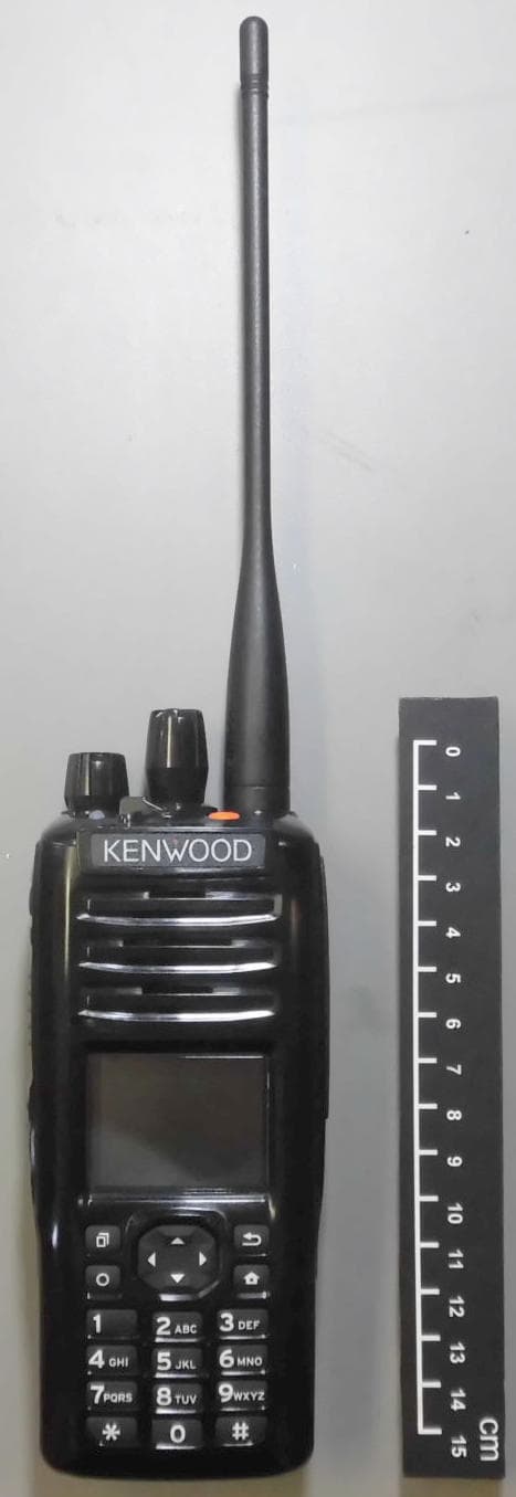
ALH442000
Jul 06, 2014Push to talk radio.
Equipment Class
DXX - Part 15 Low Power Communication Device Transmitter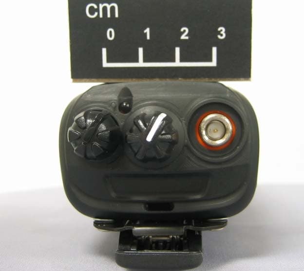
ALH443801
Dec 09, 2013UHF Digital Transceiver
Equipment Class
TNF - Licensed Non-Broadcast Transmitter Held to Face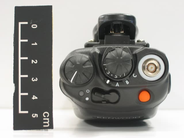
ALH468800
Oct 22, 2013PORTABLE LMR RADIO
Equipment Class
TNF - Licensed Non-Broadcast Transmitter Held to Face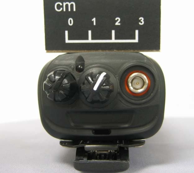
ALH443700
Aug 18, 2013VHF Digital Transceiver Models NX-240-P, NX-240-K, NX-240-M, NX-240-M2, NX-240V-K
Equipment Class
TNF - Licensed Non-Broadcast Transmitter Held to Face
ALH443800
Aug 07, 2013Model NX-340 Digital Transceiver
Equipment Class
TNF - Licensed Non-Broadcast Transmitter Held to Face