ALH442000Push to talk radio.
Kenwood USA Corporation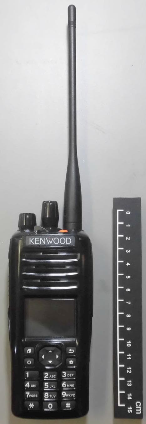
Click to zoom
Application Details
- Equipment Class
- DXX - Part 15 Low Power Communication Device Transmitter
- Date of Grant
- Jul 06, 2014
- Application Purpose
- Original Equipment
- Date of Application
- Jul 06, 2014
- Equipment Note
- Push to talk radio.
- Frequency Range
- 2402.00000000 - 2480.00000000
- Company
- Kenwood USA Corporation
- Country
- United States
Documents & Files
Document Text
Text extracted from the exhibit documents filed with the FCC. Open a document above to read the original.
Users Manual
B5A-****-00 (K) USER GUIDE NX-5200 NX-5300 NX-5400 VHF DIGITAL TRANSCEIVER/ UHF DIGITAL TRANSCEIVER 700/800MHz DIGITAL TRANSCEIVER NX-5200/ NX-5300 NX-5400 USER GUIDE ENGLISH Firmware Copyrights The title to and ownership of copyrights for fi rmware embedded in KENWOOD product memories are reserved for JVC KENWOOD Corporation. NXDN™ NXDN™ is a protocol name for a new digital communications system using 4-level FSK technology which has been co- developed by JVC KENWOOD and Icom. This device made under license under one or more of the following US Patents: 5,502,767. The AMBE+2 TM voice coding Technology embodied in this product is protected by intellectual property rights including patent rights, copyrights and trade secrets of Digital Voice Systems, Inc. This voice coding Technology is licensed solely for use within this Communications Equipment. The user of this Technology is explicitly prohibited from attempting to extract, remove, decompile, reverse engineer, or disassemble the Object Code, or in any other way convert the Object Code into a human-readable form. U.S. Patent Nos. #5,826,222, #5,754,974, #5,701,390, #5,715,365, #5,649,050, #5,630,011 and #5,581,656 Terminal Descriptions Universal connector It is possible to use a resin-based cover for the Universal connector. No.Name Description Specifi cationI/O 1SSWExt/Int Speaker Switch InputHi: INT, Low: EXTI 2SP+BTL Output + for External SpeakerStandard load 8 O 3SP-BTL Output – for External SpeakerStandard load 8 O 4MSW Ext/Int MIC Switch Input Hi: INT, Low: EXTI 5EMC External MIC InputImpedance: 1.8 k I 6ME External MIC GND –– 7PTTExternal PTT InputLow: PTT ONI 8PFProgramable Function Key Input Input voltage: 0 V - 3.3 VI 9OPTAux I/O Port (for EXT Option) I: 0 V - 3.3 V O: Standard load 25 k I/O 10EGNDGND− 115V5V 5V power supply output Max output current: 140 mA O 12TXDSerial Data OutputBaud rate: 115200 bps maxO 13RXDSerial Data InputBaud rate: 115200 bps maxI 14EMCExternal MIC inputImpedance: 1.8 k I Antenna Terminal 50 impedance i THANK YOU We are grateful you have chosen KENWOOD for your land mobile radio applications. This Users Guide covers only the basic operations of your portable radio. Ask your dealer for information on any customized features they may have added to your radio. For using details instruction manual, refer to the following URL. http://manual2.jvckenwood.com/en_contents/search/ NOTICES TO THE USER ◆ Government law prohibits the operation of unlicensed radio transmitters within the territories under government control. ◆ Illegal operation is punishable by fi ne and/or imprisonment. ◆ Refer service to qualifi ed technicians only. SAFETY: It is important that the operator is aware of and understands hazards common to the operation of any transceiver. ii One or more of the following statements may be applicable: FCC WARNING This equipment generates or uses radio frequency energy. Changes or modifi cations to this equipment may cause harmful interference unless the modifi cations are expressly approved in the instruction manual. The user could lose the authority to operate this equipment if an unauthorized change or modifi cation is made. INFORMATION TO THE DIGITAL DEVICE USER REQUIRED BY THE FCC This equipment has been tested and found to comply with the limits for a Class B digital device, pursuant to Part 15 of the FCC Rules. These limits are designed to provide reasonable protection against harmful interference in a residential installation. This equipment generates, uses and can generate radio frequency energy and, if not installed and used in accordance with the instructions, may cause harmful interference to radio communications. However, there is no guarantee that the interference will not occur in a particular installation. If this equipment does cause harmful interference to radio or television reception, which can be determined by turning the equipment off and on, the user is encouraged to try to correct the interference by one or more of the following measures: • Reorient or relocate the receiving antenna. • Increase the separation between the equipment and receiver. • Connect the equipment to an outlet on a circuit different from that to which the receiver is connected. • Consult the dealer for technical assistance. The RBRC Recycle seal found on KENWOOD nickel metal hydride (Ni-MH) battery packs indicates KENWOOD’s voluntary participation in an industry program to collect and recycle Ni-MH batteries after their operating life has expired. The RBRC program is an alternative to disposing Ni-MH batteries with your regular refuse or in municipal waste streams, which is illegal in some areas. For information on Ni-MH battery recycling in your area, call (toll free) 1-800-8-BATTERY (1-800-822-8837). KENWOOD’s involvement in this program is part of our commitment to preserve our environment and conserve our natural resources. iii The RBRC Recycle seal found on KENWOOD lithium-ion (Li-ion) battery packs indicates KENWOOD’s voluntary participation in an industry program to collect and recycle Li-ion batteries after their operating life has expired. The RBRC program is an alternative to disposing Li-ion batteries with your regular refuse or in municipal waste streams, which is illegal in some areas. For information on Li-ion battery recycling in your area, call (toll free) 1-800-8-BATTERY (1-800-822-8837). KENWOOD’s involvement in this program is part of our commitment to preserve our environment and conserve our natural resources. PRECAUTIONS • Do not charge the transceiver and battery pack when they are wet. • Ensure that there are no metallic items located between the transceiver and the battery pack. • Do not use options not specifi ed by KENWOOD. • If the die-cast chassis or other transceiver part is damaged, do not touch the damaged parts. • If a headset or headphone is connected to the transceiver, reduce the transceiver volume. Pay attention to the volume level when turning the squelch of…
Text truncated - open the document above for the full version.
Cover Letter(s)
Kenwood USA Corporation 3970 Johns Creek Court, Suwanee, GA 30024 (678) 474-4700 December 2, 2013 Federal Communications Commission Authorization & Evaluation Division 7345 Oakland Mills Road Columbia, Maryland 21046 To Whom It May Concern: This letter will authorize Compliance Testing LLC to act as our Agent in all FCC matters. This appointment is effective until otherwise notified by us. This is to advise that we are in full compliance with the Anti-Drug Abuse Act. The Applicant is not subject to a denial of federal benefits pursuant to Section 5301 of the Anti-Drug Abuse Act of 1988, 21 USC 862, and no party to the application is subject to a denial of federal benefits pursuant to that section. Sincerely,
Cover Letter(s)
Kenwood USA Corporation 3970 Johns Creek Court, Suwanee, GA 30024 (678) 474-4700 Jun. 17, 2014 Federal Communications Commission 7435 Oakland Mills Road Columbia, MD 21046 Attn: Reviewing Engineer RE: CONFIDENTIALITY REQUEST FOR MODEL: NX-5400-K2/-K3/-F2/-F3, FCC ID: ALH442000. To Whom It May Concern: This letter serves as an official request for permanent confidentiality pursuant to 47 CFR Section 0.459 of the Commission Rules. We have requested that the Block Diagram, Schematic Diagrams, Circuit Description, Parts List, Active Devices and Tuning Procedure required to be submitted with this application be withheld from public review. The documents are company proprietary information that should never get into the possession of our competition. Please contact me if you require any additional information. Sincerely,
Cover Letter(s)
Page 1 of 1 FCC ID: ALH442000 IC ID: 282D-442000 CT Project: 1460001 From: Shawn McMillen Date: 06/26/2014 1) In the SAR report you have several items that are over the 7.0mW/g occupational. Please read part of the KDB 865664. CT - Please see updated SAR report with additional plots. 2) Per 15.247(d) conducted spurious emission need to demonstrate that emissions are attenuated below the carrier by 20dB in a 100KHz RBW. The conducted spurious emission plots do not appear to show this. In addition it is unclear as to why the display line is set to -53dBm where this measurement is meant to be relative not absolute. Also if a filter was used, which probably doesn’t need to be since the carrier is so low, this would need to be documented and the level of the carrier would need to be reported per 100kHz. CT – The high pass filtered used is documented in the test equipment utilized section of the Test in question. The filter is also listed in the test equipment utilized list on pg. 29. Using the band edge test plots on pg. 16 and pg. 17, which are taken at 100kHz RBW, it is easily determined the conducted spurious emissions are well below the -20dBc limit. The -53dBm display line is for operator reference only and does not determine compliance in this test. 3) Require clarification. In the test report the 20dBc at the band edges reported on pages 16 and 17 were performed radiated whereas the spurious emission per 15.247(d) in 100KHz were performed conducted. Please explain the rational for the different approaches. CT – As stated within the Test Procedure (pg. 15 and pg. 10), the measurements were performed conducted for both mentioned measurements. 4) The section containing the dwell time does not sufficiently provide enough information that the EUT meets the rules. There is no calculation of the dwell time nor the amount of pulses within a period of time. CT – The Test Report shows the timing of the hopping frequency. Using the customer’s pseudo random timing details it is shown that the device complies to the .4 second specification. 5) The EMC report is missing the Canadian cross reference requirements. CT – Cross Reference sheet has been supplied 6) The information that the Bluetooth meets the pseudo random requirements needs to be provided. CT – Please see updated Circuit Description Exhibit. 7) The operational description of the Bluetooth indicates that it has extended data rates in addition to GFSK. Only GFSK was tested. CT – Additional plots have been added to the test report to cover all data rates. Response by: Compliance Testing LLC Submitted by: CTL Date: 7/2/14
Cover Letter(s)
Page 1 of 1 FCC ID: ALH442000 IC ID: 282D-442000 CT Project: 1460001 From: Shawn McMillen Date: 06/23/2014 Curious as to why only the two worst case scans were provided in the SAR report for head and body conditions. CT - The FCC and IC require only the highest SAR value plot for each exposure configuration (Head or body, modulation, frequency band). The NX-5400-K2 has only two exposure configurations: 1) Head, FM, 800 MHz and 2) Body, FM, 800 MHz. These are the two plots that I have included in the report. This is justified in KDB 865664 D02 page 5, section 2.3 paragraph 8. This is a composite filing. Please indicate where the test report, documentation, information etc can be located for the Bluetooth. CT - The Test Report was accidentally left out of the upload and will be provided. The radiated test setup photos for part 90 show the EUT with an antenna installed however the block diagram in the EMC report demonstrates a load was used. Please indicate if a load was used per TIA- 603. CT - The test was performed using the manufacturer supplied antenna as it is impedance matched with the device, it is the worst case measurement and still remains compliant. Is the 6.25kHz channel spacing exempt from audio and filter response measurements? CT - This radio is digitally filtered, therefore it’s modulation curves are almost identical regardless of the emissions which is evident by the modulation tests already performed within the report. Response by: Compliance Testing LLC Submitted by: CTL Date: 6/26/14
External Photos
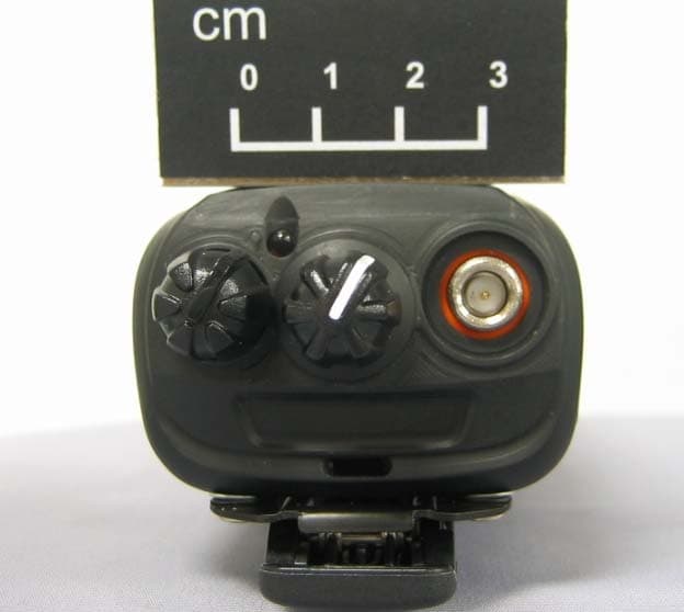
NX-5400-K2/-K3/-F2/-F3 FCC ID : ALH442000 NX-5400-K2/-K3 IC : 282D-442000 Front View (NX-5400-K2/-F2) Front View (NX-5400-K3/-F3) NX-5400-K2/-K3/-F2/-F3 FCC ID : ALH442000 NX-5400-K2/-K3 IC : 282D-442000 Left View (NX-5400-K2/-K3/-F2/-F3) Right View (NX-5400-K2/-K3/-F2/-F3) NX-5400-K2/-K3/-F2/-F3 FCC ID : ALH442000 NX-5400-K2/-K3 IC : 282D-442000 Rear View (NX-5400-K2/-K3/-F2/-F3) NX-5400-K2/-K3/-F2/-F3 FCC ID : ALH442000 NX-5400-K2/-K3 IC : 282D-442000 Top View (NX-5400-K2/-K3/-F2/-F3) Bottom View (NX-5400-K2/-K3/-F2/-F3)
ID Label/Location Info
NX-5400-K2/K3/F2/F3 FCC ID: ALH442000 IC: 282D-442000 NX-5400-K2/K3/F2/F3 FCC ID: ALH442000 IC: 282D-442000 NX-5400-K2/K3/F2/F3 FCC ID: ALH442000 IC: 282D-442000 NX-5400-K2/K3/F2/F3 FCC ID: ALH442000 IC: 282D-442000
Internal Photos
NX-5400-K2/-K3/-F2/-F3 FCC ID : ALH442000 NX-5400-K2/-K3 IC : 282D-442000 NX-5400-K2, F2 Display Unit NX-5400-K2/-K3/-F2/-F3 FCC ID : ALH442000 NX-5400-K2/-K3 IC : 282D-442000 NX-5400-K3, F3 Display Unit NX-5400-K2/-K3/-F2/-F3 FCC ID : ALH442000 NX-5400-K2/-K3 IC : 282D-442000 NX-5400-K2, F2 Front Key NX-5400-K2, F2 Front Key NX-5400-K2/-K3/-F2/-F3 FCC ID : ALH442000 NX-5400-K2/-K3 IC : 282D-442000 NX-5400-K3, F3 Front Key NX-5400-K3, F3 Front Key NX-5400-K2/-K3/-F2/-F3 FCC ID : ALH442000 NX-5400-K2/-K3 IC : 282D-442000 NX-5400-K2, K3, F2, F3 Display Unit NX-5400-K2/-K3/-F2/-F3 FCC ID : ALH442000 NX-5400-K2/-K3 IC : 282D-442000 NX-5400-K2, K3, F2, F3 Side Key NX-5400-K2/-K3/-F2/-F3 FCC ID : ALH442000 NX-5400-K2/-K3 IC : 282D-442000 NX-5400-K2, K3, F2, F3 Side Key NX-5400-K2, K3, F2, F3 Side Key NX-5400-K2/-K3/-F2/-F3 FCC ID : ALH442000 NX-5400-K2/-K3 IC : 282D-442000 NX-5400-K2, K3, F2, F3 MAIN UNIT NX-5400-K2/-K3/-F2/-F3 FCC ID : ALH442000 NX-5400-K2/-K3 IC : 282D-442000 NX-5400-K2, K3, F2, F3 MAIN UNIT NX-5400-K2/-K3/-F2/-F3 FCC ID : ALH442000 NX-5400-K2/-K3 IC : 282D-442000 NX-5400-K2, K3, F2, F3 MAIN UNIT NX-5400-K2/-K3/-F2/-F3 FCC ID : ALH442000 NX-5400-K2/-K3 IC : 282D-442000 NX-5400-K2, K3, F2, F3 MAIN UNIT NX-5400-K2/-K3/-F2/-F3 FCC ID : ALH442000 NX-5400-K2/-K3 IC : 282D-442000 NX-5400-K2, K3, F2, F3 MAIN UNIT
RF Exposure Info
802 N. Twin Oaks Valley Road, Suite 105 • San Marcos, CA 92069 • U.S.A. TEL (760) 471-2100 • FAX (760) 471-2121 http://www.rfexposurelab.com CERTIFICATE OF COMPLIANCE SAR EVALUATION Kenwood USA Corporation Dates of Test: June 12 – 13, 2014 3970 Johns Creek Court, Suite 100 Test Report Number: SAR.20140606 Suwanee, GA 30024 Revision A This wireless mobile and/or portable device has been shown to be compliant for localized specific absorption rate (SAR) for uncontrolled environment/general exposure limits specified in ANSI/IEEE Std. C95.1-1992 and had been tested in accordance with the measurement procedures specified in IEEE 1528-2013 and EN/IEC 62209:2010 (See test report). I attest to the accuracy of the data. All measurements were performed by myself or were made under my supervision and are correct to the best of my knowledge and belief. I assume full responsibility for the completeness of these measurements and vouch for the qualifications of all persons taking them. RF Exposure Lab, LLC certifies that no party to this application is subject to a denial of Federal benefits that includes FCC benefits pursuant to Section 5301 of the Anti-Drug Abuse Act of 1988, 21 U.S.C. 853(a). Jay M. Moulton Vice President Testing Cert. # 2387.01 FCC ID: ALH442000 IC Certificate: 282D-442000 Model(s): NX-5400-K2, NX-5400-K3 Test Sample: Engineering Unit Same as Production Serial Number: 174 Equipment Type: Push-To-Talk Handheld Radio for Occupational Use Classification: Portable Transmitter Next to Face and Body TX Frequency Range: 769 – 775 MHz; 799 – 805 MHz; 806 – 824 MHz; 851 – 869 MHz; 2402 – 2480 MHz Frequency Tolerance: ± 2.5 ppm Maximum RF Output: 800 MHz – 34.77 dBm; 2450 MHz – 4.00 dBm Conducted Signal Modulation: FM Body Worn Accessories: Model KBH-11 Audio Accessories: Model KMC-54WD, KHS-11BL, KHS-11BE Antenna Type: KRA-32, KRA-36 Battery: Standard (Model KNB-L2, KNB-L3) Application Type: Certification FCC Rule Parts: Part 2, 90 KDB Test Methodology: KDB 447498 DO1 v05r02, KDB 643646 D01 v01r01, KDB 865664 D01 v01r01, KDB 865664 D02 v01 Industry Canada: RSS-102, Safety Code 6 Maximum SAR Value: 1.49 W/kg for Face; 4.81 W/kg for Body Reported Maximum Simultaneous SAR: 1.51 W/kg for Face; 4.83 W/kg for Body Reported Separation Distance: 25 mm for Face; 0 mm for Body © 2014 RF Exposure Lab, LLC This report shall not be reproduced except in full without the written approval of RF Exposure Lab, LLC. Report Number: SAR.20140606 Table of Contents 1. Introduction ........................................................................................................................ 3 SAR Definition [5] ................................................................................................................... 4 2. SAR Measurement Setup ................................................................................................... 5 Robotic System ...................................................................................................................... 5 System Hardware ................................................................................................................... 5 System Electronics ................................................................................................................. 6 Probe Measurement System .................................................................................................. 6 3. Probe and Dipole Calibration .............................................................................................11 4. Phantom & Simulating Tissue Specifications .....................................................................12 Head & Body Simulating Mixture Characterization ................................................................12 5. ANSI/IEEE C95.1 – 1992 RF Exposure Limits [2] ..............................................................13 Uncontrolled Environment .....................................................................................................13 Controlled Environment .........................................................................................................13 6. Measurement Uncertainty .................................................................................................14 7. System Validation..............................................................................................................15 Tissue Verification .................................................................................................................15 Test System Verification ........................................................................................................15 8. SAR Test Data Summary ..................................................................................................16 Procedures Used To Establish Test Signal ...........................................................................16 Device Test Condition ...........................................................................................................16 Radio Body Test .......................................................................................................................17 SAR Data Summary – Head SAR Face Measurements ........................................................20 SAR Data Summary – Body SAR Measurements .................................................................21 SAR Data Summary – Simultaneous Evaluation ...................................................................22 9. Test Equipment List ...........................................................................................................23 10. Conclusion ....................................................................................................................24 11. References ....................................................................................................................25 Appendix A – System Validation Plots and Data ..............................…
Text truncated - open the document above for the full version.
Test Report
p1460001_FCC_Part 15.247_FHSS_Rev 2.0 Page 1 of 33 Test Report Prepared for: Kenwood USA Corporation Model: NX-5400-K2, NX-5400-K3, NX-5400-F2, NX-5400-F3 Description: 700/800MHz P25 TRANSCEIVER with Bluetooth To FCC Part 15.247 FHSS Date of Issue: June 27, 2014 On the behalf of the applicant: Kenwood USA Corporation Communications Division 3970 Johns Creek Court Suwanee, GA 30024 Attention of: Joel Berger, Research & Development Ph: (678) 474-4722 E-mail: [email protected] Prepared by Compliance Testing, LLC 1724 S. Nevada Way Mesa, AZ 85204 (480) 926-3100 phone / (480) 926-3598 fax www.compliancetesting.com Project No: p1460001 Alex Macon Project Test Engineer This report may not be reproduced, except in full, without written permission from Compliance Testing All results contained herein relate only to the sample tested p1460001_FCC_Part 15.247_FHSS_Rev 2.0 Page 2 of 33 Test Report Revision History Revision Date Revised By Reason for Revision 1.0 June 12, 2014 Alex Macon Original Document 2.0 June 27, 2014 Alex Macon Additional dwell time plots of been added to the test section p1460001_FCC_Part 15.247_FHSS_Rev 2.0 Page 3 of 33 Table of Contents Description Page The applicant has been cautioned as to the following .............................................................................. 5 Standard Test Conditions and Engineering Practices .............................................................................. 6 Peak Output Power ................................................................................................................................... 9 Conducted Spurious Emissions .............................................................................................................. 10 Radiated Spurious Emissions ................................................................................................................. 14 Emissions at Band Edges ....................................................................................................................... 15 Occupied Bandwidth ............................................................................................................................... 21 Dwell Time .............................................................................................................................................. 22 Number of Hopping Channels ................................................................................................................ 27 Channel Spacing .................................................................................................................................... 30 A/C Powerline Conducted Emissions ..................................................................................................... 31 Test Equipment Utilized .......................................................................................................................... 33 p1460001_FCC_Part 15.247_FHSS_Rev 2.0 Page 4 of 33 ILAC / A2LA Compliance Testing, LLC, has been accredited in accordance with the recognized International Standard ISO/IEC 17025:2005. This accreditation demonstrates technical competence for a defined scope and the operation of a laboratory quality management system (refer joint ISO-ILAC-IAF Communiqué dated January 2009) The tests results contained within this test report all fall within our scope of accreditation, unless noted in the table below. Please refer to http://www.compliancetesting.com/labscope.html for current scope of accreditation. Testing Certificate Number: 2152.01 FCC Site Reg. #349717 IC Site Reg. #2044A-2 Non-accredited tests contained in this report: N/A p1460001_FCC_Part 15.247_FHSS_Rev 2.0 Page 5 of 33 The applicant has been cautioned as to the following 15.21 - Information to User The user’s manual or instruction manual for an intentional radiator shall caution the user that changes or modifications not expressly approved by the party responsible for compliance could void the user’s authority to operate the equipment. 15.27(a) - Special Accessories Equipment marketed to a consumer must be capable of complying with the necessary regulations in the configuration in which the equipment is marketed. Where special accessories, such as shielded cables and/or special connectors are required to enable an unintentional or intentional radiator to comply with the emission limits in this part, the equipment must be marketed with, i.e. shipped and sold with, those special accessories. However, in lieu of shipping or packaging the special accessories with the unintentional or intentional radiator, the responsible party may employ other methods of ensuring that the special accessories are provided to the consumer, without an additional charge. Information detailing any alternative method used to supply the special accessories for a grant of equipment authorization or retained in the verification records, as appropriate. The party responsible for the equipment, as detailed in 2.909 of this chapter, shall ensure that these special accessories are provided with the equipment. The instruction manual for such devices shall include appropriate instructions on the first page of text concerned with the installation of the device that these special accessories must be used with the device. It is the responsibility of the user to use the needed special accessories supplied with the equipment. p1460001_FCC_Part 15.247_FHSS_Rev 2.0 Page 6 of 33 Standard Test Conditions and Engineering Practices All tests and measurement data shown were performed in accordance with FCC Rules and Regulations, Volume II; Part 2 and the following individual Parts: 15.247 Operation within bands 902-928 MHz, 2400-2483.5 MHz, and 5725-5850 MHz. Except as noted herein, the following conditions and procedures were observed during the testing: In accordance with ANSI C63.4-2009, ANSI C63.10-2009, FCC DA 00-705, and unless otherwise indicated in the specific measurement results, the ambient te…
Text truncated - open the document above for the full version.
Test Setup Photos
Test Setup Photos FCC ID: ALH442000 IC: 282D-442000 RF Conducted #1 Test Setup Photos FCC ID: ALH442000 IC ID: 282D-442000 RF Conducted #1 RF Conducted #2 RF Radiated #1 RF Radiated #2 RF Radiated #1 RF Radiated #2 A/C Line Conduction #1 A/C Line Conduction #2
Contact Information
Applicant
Angelina Seay(Regulatory Support Engineer)
Test Firm
Compliance Testing, LLCMichael Schafer
Technical Specifications
| # | Rule Parts | Frequency Range | Power Output |
|---|---|---|---|
| 1 | 15C | 2.40 GHz - 2.48 GHz | 1.46 mW |
Other Applications from Kenwood USA Corporation
ALH443801
Dec 09, 2013UHF Digital Transceiver
Equipment Class
TNF - Licensed Non-Broadcast Transmitter Held to Face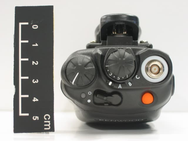
ALH468800
Oct 22, 2013PORTABLE LMR RADIO
Equipment Class
TNF - Licensed Non-Broadcast Transmitter Held to Face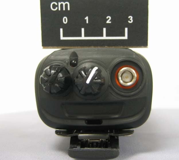
ALH443700
Aug 18, 2013VHF Digital Transceiver Models NX-240-P, NX-240-K, NX-240-M, NX-240-M2, NX-240V-K
Equipment Class
TNF - Licensed Non-Broadcast Transmitter Held to Face
ALH443800
Aug 07, 2013Model NX-340 Digital Transceiver
Equipment Class
TNF - Licensed Non-Broadcast Transmitter Held to Face
ALH459700
Jul 29, 2013Models PKT-03-K, PKT-03-M
Equipment Class
TNF - Licensed Non-Broadcast Transmitter Held to Face