ALH31251110AMATEUR TRANSMITTER WITH SCANNING RECEIVER
Kenwood USA Corporation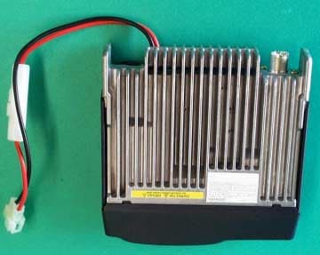
Click to zoom
Application Details
- Equipment Class
- CSR - Scanning Receiver
- Date of Grant
- Sep 25, 2003
- Application Purpose
- Original Equipment
- Date of Application
- Sep 25, 2003
- Equipment Note
- AMATEUR TRANSMITTER WITH SCANNING RECEIVER
- Frequency Range
- 136.00000000 - 173.99500000
- Company
- Kenwood USA Corporation
- Country
- United States
Documents & Files
Document Text
Text extracted from the exhibit documents filed with the FCC. Open a document above to read the original.
Users Manual
© B62-1738-00 (K,E,M2) 09 08 07 06 05 04 03 02 01 00 INSTRUCTION MANUAL 144 MHz FM TRANSCEIVER TM-271A/ TM-271E TM-271MENU THANK YOU! Thank you for choosing this KENWOOD transceiver. KENWOOD always provides Amateur Radio products which surprise and excite serious hobbyists. This transceiver is no exception. As you learn how to use this transceiver, you will find that KENWOOD is pursuing “user friendliness”. For example, each time you change the Menu No. in Menu mode, you will see a text message on the display that lets you know what you are configuring. Though user friendly, this transceiver is technically sophisticated and some features may be new to you. Consider this manual to be a personal tutorial from the designers. Allow the manual to guide you through the learning process now, then act as a reference in the coming years. KENWOOD believes that this product will satisfy your requirements on both voice and data communications. MODELS COVERED BY THIS MANUAL The models listed below are covered by this manual. TM-271A:144 MHz FM Transceiver TM-271E:144 MHz FM Transceiver MARKET CODES K:The Americas E:Europe M n:General (Where “n” represents a variation number.) The market code is printed on the bar-code label of the carton box. Refer to the product specifications {pages 71 ~ 72} for information on the available operating frequencies within each model. For accessories supplied with the model, refer to page 1. FEATURES •Weather Alert Radio function checks the 1050 Hz tone from NOAA (U.S.A./ Canada only). •Menu allows for easy control and selecting of various functions. •Up to 200 memory channels to program frequencies and other various data. (Up to 100 memory channels if Memory Channel Names are assigned to the channels.) •Continuous Tone Coded Squelch System (CTCSS) or Digital Code Squelch (DCS) rejects unwanted calls from other stations. •Equipped with an easy-to-read large LCD with alphanumeric display capability. •TNC (E market models only) •Free PC software (Memory Control Program) is available to program the frequency, signalling, and other settings of your transceiver. The MCP can be downloaded at: http://www.kenwood.com/i/products/info/amateur.html i PRECAUTIONS Please observe the following precautions to prevent fire, personal injury, and/or transceiver damage: •Do not attempt to configure your transceiver while driving; it is simply too dangerous. •Be aware of local laws pertaining to the use of headphones/headsets while driving on public roads. If in doubt, do not wear headphones while mobiling. •Do not transmit with high output power for extended periods; the transceiver may overheat. •Do not modify the transceiver unless instructed by this manual or other KENWOOD documentation. •Do not expose the transceiver to long periods of direct sunlight nor place it close to heating appliances. •Do not place the transceiver in excessively dusty, humid or wet areas, nor on unstable surfaces. •If an abnormal odor or smoke is detected coming from the transceiver, turn OFF the power immediately. Contact a KENWOOD service station or your dealer. •This transceiver is designed for a 13.8 V power source. Never use a 24 V battery to power the transceiver. NOTICES TO THE USER One or more of the following statements may be applicable: FCC WARNING This equipment generates or uses radio frequency energy. Changes or modifications to this equipment may cause harmful interference unless the modifications are expressly approved in the instruction manual. The user could lose the authority to operate this equipment if an unauthorized change or modification is made. INFORMATION TO THE DIGITAL DEVICE USER REQUIRED BY THE FCC This equipment has been tested and found to comply with the limits for a Class B digital device, pursuant to Part 15 of the FCC Rules. These limits are designed to provide reasonable protection against harmful interference in a residential installation. This equipment generates, uses and can generate radio frequency energy and, if not installed and used in accordance with the instructions, may cause harmful interference to radio communications. However, there is no guarantee that the interference will not occur in a particular installation. If this equipment does cause harmful interference to radio or television reception, which can be determined by turning the equipment off and on, the user is encouraged to try to correct the interference by one or more of the following measures: •Reorient or relocate the receiving antenna. •Increase the separation between the equipment and receiver. •Connect the equipment to an outlet on a circuit different from that to which the receiver is connected. •Consult the dealer for technical assistance. When condensation occurs inside the transceiver: Condensation may occur inside the transceiver when the room is warmed using a heater on a cold day or when the transceiver is quickly moved from a cold location to a warm location. When condensation occurs, the microcomputer and/or the transmit/receive circuits may become unstable, resulting in transceiver malfunction. If this happens, turn OFF the transceiver and wait for a while. When the condensed droplets disappear, the transceiver will function normally. ii CONTENTS SELECTING A FREQUENCY.................................. 15 VFO MODE.......................................................... 15 MHz MODE.......................................................... 16 DIRECT FREQUENCY ENTRY...................................... 16 CHAPTER5MENU SETUP WHAT IS A MENU?................................................. 18 MENU ACCESS...................................................... 18 MENU FUNCTION LIST.......................................... 19 CHAPTER 6OPERATING THROUGH REPEATERS OFFSET PROGRAMMING FLOW........................... 22 PROGRAMMING AN OFFSET................................ 23 SELECTING AN OFFSET DIRECTION.............................. 23 SELECTING AN OFFSET FREQUENCY............................ …
Text truncated - open the document above for the full version.
Attestation Statements
Letter of Attestation Model: TM-271A-1 Scanning receiver This letter attests to the fact that Kenwood scanner receiver model TM-271A-1 meets the requirements of the FCC Rules, 15.121(a). Compliance is achieved through the following method(s): (1). The Microprocessor is hard coded to not accept programming, selection, scanning or direct entry of Cellular band frequencies. (2). Filtering precludes reception of mixer images or harmonics of Cellular band frequencies. (3). Subminiature SMD assembly and inaccessible multiplayer PCB construction all but precludes attempts at circuit hardware modifications.
Cover Letter(s)
9/22/2003 Federal Communications Commission EQUIPMENT APPROVAL SERVICES P.O. Box 358315 Pittsburgh, PA 15251-5315 Attention: Authorization and Evaluation Division Reference: FCC ID: ALH31251110 Model TM-271A-1 Dear Sir: Pursuant to Sections 0.457(d)(1)(ii) and 0.459 of the Commission's Rules, the Applicant hereby requests confidential treatment of some of the information accompanying this Application, as listed below: Block Diagram Schematic Diagrams Circuit Description Frequency construction These materials contain trade secrets and proprietary information not customarily released to the public. The public disclosure of these matters might be harmful to the Applicant and provide unjustified benefits to its competitors. The Applicant understands that pursuant to Rule 0.457 (d)(1)(ii), disclosure of the Application and all accompanying documentation will not be made before the date of Grant for the Application. Sincerely yours, Morton Flom, P. Eng.
External Photos
Model Name: TM-271A-1 FCC ID: ALH31251110 Front View Front ViewFront View Front View Rear View Rear ViewRear View Rear View Model Name: TM-271A-1 FCC ID: ALH31251110 Top view Top viewTop view Top view Bottom view Bottom viewBottom view Bottom view Model Name: TM-271A-1 FCC ID: ALH31251110 Right view Right viewRight view Right view Left view Left viewLeft view Left view
ID Label/Location Info
Model Name: TM-271A-1 FCC ID: ALH31251110 Bottom view Bottom viewBottom view Bottom view Right view Right viewRight view Right view
Test Report
FCC ID: ALH31251110 Certification Of FCC ID: ALH31251110 Receiver Model: TM-271A-1 to Federal Communications Commission Rule Parts 15.101, 15.121, Confidentiality Date of Report: August 27, 2003 On the Behalf of the Applicant: Kenwood USA Corporation At the Request of: P.O. JB-F-006 Kenwood USA Corporation Communications Division 3975 Johns Creek Court, Suite 300 Suwanee, GA 30024 Attention of: Joel E. Berger, Research & Development [email protected] (678) 474-4722; FAX: -4731 Supervised By: Morton Flom, P. Eng. MFA p0380004, d0380073 FCC ID: ALH31251110 Table of Contents Rule Description Page 2.948 Description of Measurement Facilities 1 15.109 Receiver Spurious Emissions (Radiated) 6 15.121(b) Scanning Receiver 11 MFA p0380004, d0380073 FCC ID: ALH31251110 Page Number 1 of 12. Required information per ISO/IEC Guide 25-1990, paragraph 13.2: a) Test Report b) Laboratory: (FCC: 31040/SIT) (Canada: IC 2044) M. Flom Associates, Inc. 3356 N. San Marcos Place, Suite 107 Chandler, AZ 85225 c) Report Number: d0380073 d) Client: Kenwood USA Corporation Communications Division 3975 Johns Creek Court, Suite 300 Suwanee, GA 30024 e) Identification: TM-271A-1 FCC ID: ALH31251110 Description: Amateur Transmitter with Scanning Receiver f) EUT Condition: Not required unless specified in individual tests. g) Report Date: August 27, 2003 EUT Received: August 4, 2003 h, j, k): As indicated in individual tests. i) Sampling method: No sampling procedure used. l) Uncertainty: In accordance with MFA internal quality manual. m) Supervised by: Morton Flom, P. Eng. n) Results: The results presented in this report relate only to the item tested. o) Reproduction: This report must not be reproduced, except in full, without written permission from this laboratory. MFA p0380004, d0380073 FCC ID: ALH31251110 Page Number 2 of 12. M. Flom Associates, Inc. is accredited by the American Association for Laboratory Association (A2LA) as shown in the scope below. "This laboratory is accredited by the American Association for Laboratory Accreditation (A2LA) and the results shown in this report have been determined in accordance with the laboratory's terms of accreditation unless stated otherwise in the report." Should this report contain any data for tests for which we are not accredited, or which have been undertaken by a subcontractor that is not A2LA accredited, such data would not covered by this laboratory's A2LA accreditation. MFA p0380004, d0380073 FCC ID: ALH31251110 Page Number 3 of 12. General Information Part 2.948: (a)(b) Description Of Measurement Facilities: File: 31040/SIT A description of the measurement facilities was filed with the Commission and was found to be in compliance with the requirements of Section 2.948, by letter dated March 4, 2003. All pertinent changes will be reported to the Commission by up-date prior to March 2006. (b)(4) Supporting Structures: Sketch - Attached Exhibits (b)(5)(6) Test Instrumentation: List - See Exhibits 2.925: Identification of an Authorized Device: Drawing - See Exhibits Location of Label - See Photos Name and Address of Applicant: Kenwood USA Corporation Communications Division 3975 Johns Creek Court, Suite 300 Suwanee, GA 30024 MFA p0380004, d0380073 FCC ID: ALH31251110 Page Number 4 of 12. 2.911: 2.1033(b)(6) Technical Report Manufacturer: Kenwood Electronics Technologies PTE Ltd. 1 Ang Mo Kio Street 63 Singapore 569110 Trade Name: Kenwood FCC ID: ALH31251110 Model Number: TM-271A-1 Photographs: See List of Exhibits DUT Description: This unit Passes 15.31: Measurement Standard & Procedure: IEEE Standard 187 was used as a guide. FCC Measurement Procedure MP-1 x ANSI 63.4 (1992/2000) “Methods of measurement of radio-noise emissions from low-voltage electrical and electronic equipment in the range of 9 kHz to 40 GHz.” MFA p0380004, d0380073 FCC ID: ALH31251110 Page Number 5 of 12. Expository Statement 1. Number of Bands = 1 2. Number of Channels = 1 3. Tuning Range, MHz = 136 to 173.995 4. Oscillator Range, MHz = 86.05 to 124.045 5. I.F., MHz = 49.95 6. Block Diagram = Attached 7. For cellular receiver only, the radio transceiver meets the requirements of FCC Bulletin OET 53 ("Cellular System Mobile Stations-Land-System Compatibility Specification."). See attached affidavit. 15.203: Antenna Requirement: The antenna is permanently attached to the EUT The antenna uses a unique coupling The EUT must be professionally installed x The antenna requirement does not apply Supervised By: Morton Flom, P. Eng. MFA p0380004, d0380073 FCC ID: ALH31251110 Page Number 6 of 12. Name of Test: Receiver Spurious Emissions (Radiated) Specification: 15.109: Radiated Interference Limits 15.33: Frequency Range of Radiated Measurements 80.217: Suppression of Interference Aboard Ships Guide: See measurement procedure below Test Conditions: Standard Temperature & Humidity Test Equipment: As per attached page Search Antennas: 25 MHz - 300 MHz: Emco 3109 Biconical 200 MHz - 1 GHz: Aprel 2001 Log Periodic 1 GHz - 18 GHz: Emco 3115 Horn 10 GHz - 40 GHz: Emco 3116 Horn with HP11970A Mixer Measurement Procedure 1. At first, bench tests were performed to locate the spurious emissions at the antenna terminals. 2. In the field, tests were conducted over the range shown, The test sample was set up on a wooden turntable above ground, and at a distance of three meters from the antenna connected tot he Spectrum Analyzer. 3. In order to obtain the maximum response at each frequency, the turntable was rotated, and the search antenna was raised and lowered. The EUT was also adjusted for maximum response. Tests were conducted in Horizontal & Vertical polarization modes. 4. The field strength was calculated from: E μV/m @ 3 m = Log 10 -1 (dBμV + A.F. + C.L.) 20 5. Measurement Results: Attached for "Worst Case" conditions. MFA p0380004, d0380073 FCC ID: ALH31251110 Page Number 7 of 12. Radiated Test Setup NOTES: (a)Search Antenna - Rotatable on boom (b) Non-metallic boom (c) Non-metallic mast (d) Adjustable ho…
Text truncated - open the document above for the full version.
Test Setup Photos
FCC ID: ALH31251110 Page Number 8 of 12. Test Setup: Radiated Emissions MFA p0380004, d0380073
Contact Information
Applicant
Angelina Seay(Regulatory Support Engineer)
Test Firm
M. Flom Associates, Inc.Morton Flom
Technical Specifications
| # | Rule Parts | Frequency Range | Power Output |
|---|---|---|---|
| 1 | 15B | 136 MHz - 173.995 MHz | - |
Other Applications from Kenwood USA Corporation
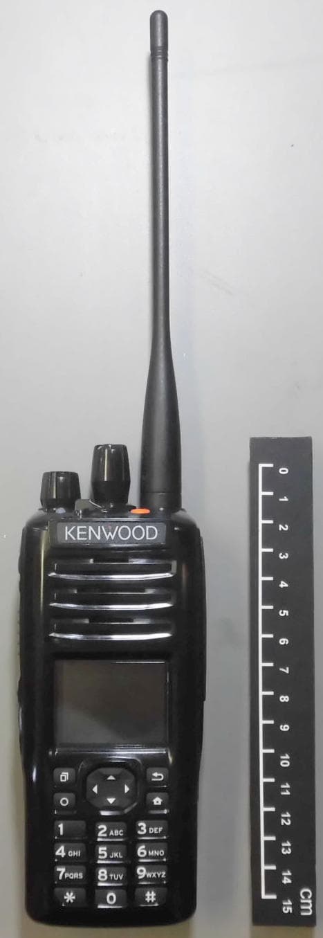
ALH442000
Jul 06, 2014Push to talk radio.
Equipment Class
DXX - Part 15 Low Power Communication Device Transmitter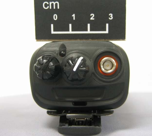
ALH443801
Dec 09, 2013UHF Digital Transceiver
Equipment Class
TNF - Licensed Non-Broadcast Transmitter Held to Face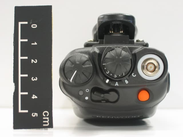
ALH468800
Oct 22, 2013PORTABLE LMR RADIO
Equipment Class
TNF - Licensed Non-Broadcast Transmitter Held to Face
ALH443700
Aug 18, 2013VHF Digital Transceiver Models NX-240-P, NX-240-K, NX-240-M, NX-240-M2, NX-240V-K
Equipment Class
TNF - Licensed Non-Broadcast Transmitter Held to Face
ALH443800
Aug 07, 2013Model NX-340 Digital Transceiver
Equipment Class
TNF - Licensed Non-Broadcast Transmitter Held to Face