ALH32933220VHF FM Transceiver
Kenwood USA Corporation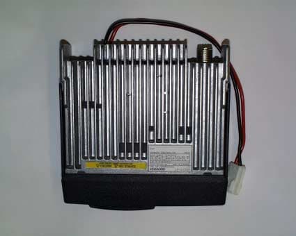
Click to zoom
Application Details
- Equipment Class
- TNB - Licensed Non-Broadcast Station Transmitter
- Date of Grant
- Feb 20, 2002
- Application Purpose
- Original Equipment
- Date of Application
- Dec 19, 2001
- Equipment Note
- VHF FM Transceiver
- Frequency Range
- 136.00000000 - 162.00000000
- Company
- Kenwood USA Corporation
- Country
- United States
Documents & Files
Document Text
Text extracted from the exhibit documents filed with the FCC. Open a document above to read the original.
Users Manual
TK-7102H INSTRUCTION MANUAL VHF FM TRANSCEIVER © B62-1596-00 (M) 09 08 07 06 05 04 03 02 01 00 KENWOOD CORPORATION TK-8102H UHF FM TRANSCEIVER i THANK YOU! We are grateful you chose KENWOOD for your personal mobile applications. We believe this easy-to-use transceiver will provide dependable communications to keep personnel operating at peak efficiency. KENWOOD transceivers incorporate the latest in advanced technology. As a result, we feel strongly that you will be pleased with the quality and features of this product. MODELS COVERED BY THIS MANUAL The models listed below are covered by this manual: •TK-7102H:VHF FM Transceiver •TK-8102H:UHF FM Transceiver NOTICES TO THE USER uGovernment law prohibits the operation of unlicensed transmitters within the territories under government control. uIllegal operation is punishable by fine and/or imprisonment. uRefer service to qualified technicians only. SAFETY: It is important that the operator is aware of, and understands, hazards common to the operation of any transceiver. uEXPLOSIVE ATMOSPHERES (GASES, DUST, FUMES, etc.) Turn OFF your transceiver while taking on fuel or while parked in gasoline service stations. Do not carry spare fuel containers in the trunk of your vehicle if your transceiver is mounted in the trunk area. uINJURY FROM RADIO FREQUENCY TRANSMISSIONS Do not operate your transceiver when somebody is either touching the antenna or standing within two to three feet of it, to avoid the possibility of radio frequency burns or related physical injury. uDYNAMITE BLASTING CAPS Operating the transceiver within 500 feet (150 m) of dynamite blasting caps may cause them to explode. Turn OFF your transceiver when in an area where blasting is in progress, or where “TURN OFF TWO-WAY RADIO” signs have been posted. If you are transporting blasting caps in your vehicle, make sure they are carried in a closed metal box with a padded interior. Do not transmit while the caps are being placed into or removed from the container. PRECAUTIONS Please observe the following precautions to prevent fire, personal injury, and transceiver damage. • Do not attempt to configure the transceiver while driving; it is too dangerous. • Do not modify the transceiver for any reason. • Do not expose the transceiver to long periods of direct sunlight, nor place it near heating appliances. • Do not place the transceiver in excessively dusty, humid, or wet areas, nor on unstable surfaces. • If an abnormal odor or smoke is detected coming from the transceiver, turn OFF the power immediately. Contact your KENWOOD dealer. ii CONTENTS UNPACKING AND CHECKING EQUIPMENT ................................... 1 S UPPLIED ACCESSORIES..................................................................... 1 PREPARATION .................................................................................. 2 T OOLS REQUIRED.............................................................................. 2 POWER CABLE CONNECTION............................................................... 2 I NSTALLING THE TRANSCEIVER.............................................................. 3 ORIENTATION .................................................................................... 4 FRONT PANEL................................................................................... 4 DISPLAY............................................................................................ 5 REAR PANEL..................................................................................... 5 BASIC OPERATIONS ........................................................................ 6 S WITCHING POWER ON/ OFF ............................................................. 6 ADJUSTING THE VOLUME..................................................................... 6 SELECTING A CHANNEL....................................................................... 6 TRANSMITTING................................................................................... 6 RECEIVING........................................................................................ 6 SCAN .................................................................................................. 7 T EMPORARY DELETE.......................................................................... 7 REVERT CHANNEL.............................................................................. 7 DTMF CALLS ..................................................................................... 8 MANUAL DIALLING............................................................................. 8 STORING DTMF NUMBERS................................................................. 8 D IALLING STORED DTMF NUMBERS.................................................... 8 CLEARING STORED DTMF NUMBERS................................................... 8 REDIALLING....................................................................................... 8 CODE SQUELCH (ID CODE) ............................................................ 9 R ECEIVING........................................................................................ 9 TRANSMITTING................................................................................... 9 ADVANCED OPERATIONS ............................................................. 10 T IME-OUT TIMER (TOT) .................................................................... 10 BUSY CHANNEL LOCKOUT (BCL) ...................................................... 10 TALK-AROUND................................................................................. 10 MONITOR........................................................................................ 10 E MERGENCY OPERATION................................................................... 11 K EY LOCK...................................................................................... 11 B EGINNING/ END OF TRANSMISSION ID SIGNAL.................................... 11 1 UNPACKING AND CHECKING EQUIPMENT Note: The follo…
Text truncated - open the document above for the full version.
Attestation Statements
August 27, 2001 Federal Communications Commission Authorization & Evaluation Division 7435 Oakland Mills Road Columbia, MD 21046 Gentlemen: Reference: This equipment meets the requirements of FCC Rules, Parts 90.203(e) and (g) as applicable. Programming of this product’s transmit frequencies can be performed ONLY by the manufacturer or by service or maintenance personnel. The operator cannot program transmit frequencies using the equipment’s external operation controls. Sincerely, Kenwood Communications Corporation Joel E. Berger Joel. E. Berger Staff Engineer Kenwood Communications Corporation Research & Development Department Corporate Headquarters Kenwood Communications Corporation 3975 Johns Creek Court, Suite 300 Suwanee, GA 30024 678-474-4700 Distribution: 2201 E. Dominguez St. Long Beach, CA 90810 (310) 639-4200 Mailing Address: P.O. Box 22745 Long Beach, CA 90801-5745
Block Diagram
1234567891011 HGFEDCBA USE FOR SYMBOL REVISION NO ISSUED DATE 12345 DESIGNED DRAWN CHECKED APPROVED PART NUMBERPART NAME 6789 - - - - - - - - - - - - - - - - - - KENWOODCORPORATION RESET SW Q5 4 SP GND 8C DAN222 50.4MHz SP CK KMI1 D801 MA4PH633 8R 8T LEDC4 3 KRC102S MA742 KRX102U IC800 LEDC3 IC101 MB15A02 POWER Q37 2SC3357 RF 5M APC VCOMOD 3 DAN222 8R 2SC4919 KRC102S 2SC4649(N,P) 5C SBC D/A VCO LEDC4 OVER VOLTAGE KMI4 DAN235E KRC102S CF2 CONTROL RESET DET NARROW IC11 KRC102S SB IC7 IC15 HOOK(RXD) TEMP2 Q31 Q6 KMI2 LEDC3 D19 MICMT LEDC2 BSHIFT Q14 D6 2SC1832(GR) KRC102S NJM2904V AVR Q7 2SJ243 8V FILTER AF Q26 KRC404RTK PLLE IC3 8T PRE IF Q23 Q13 SW RF BPF KTA1664(Y) 1SS372 M62363FP(*/8) KMI4 TRIPLER UPB1509GV IC20 LA4600 KRC102S INT 2SC4738(GR) CPU 5M PF AMP PSB 8CL 16.8MHz TC7W74FU 3SK255 IC21 CONV KRC102S SPLATTER CHARGE KMO2 IC9 IGNITION SW D43 POWER RF BPF LEDC1 AMP 2SK1824 RF TCXO WIDE 2SC4617(S) 8RC KMI1 MIC/IDC CV E MUTE BPF IC22 IC3 D18 DET NJM2100V 8R RF Q20 LEDPF 1 MIC TA75W01FU (2) POW. ANT SW (WIDE) Q4 SW D9 8C MUTE1 8TC DTMF/BEEP M62363FP(*/8) DTMF Vg NOISE ME D/A M62363FP(*/8) M62363FP(*/8) D11 IF IC10 CM SUM 784214AGC125 KIA7808AF LEDPF X2 LIPPLE Q10 5V NJM78L05UA MICBL D12 D803 XB15A709 D5 PSB Q19 LEDMON PLLE 2SC3357 VCO 5C LEDC1 D/A 8RCLEDMON Q8 DT LOOP Q5 TA75W01FU (1) 2SK508NV(K52) LEDR CONV KMI3 8C IC4 MIC 2SA1745(6,7) PTT CONV D/A CONV AF HOOKCMRESET 49.95MHz Q4 BSHIFT D/A DET KEY Q16 SW D806 8C CONV D25,26 P KMI2 KMI3 LC73872M CONV D7 LEDR SW KMI2 Q22,43 MIC VCOMOD CM BPF SW NJM2902V(*/4) X54-334*-** Q3 2SC5108(Y) KRA2555S PTT(TXD) DIVIDER Q2 BATT. CHECK 2 LEDC3 PLL IC HVC350B SW FILTER DET SW Q41 5M Q10 D21,22 RX KMI3 KRC102S D/A KMO2 AVR KMO2 KMI1 LD 8C TEMP3 IC14 Q9 PST9140NR Q30 Q1 TX-RX UNIT T/R PA BATT.CHECK (NARROW) DTC363EU SWQ3 8TC KRC102S PTT 2SK1824 IC23 AVR MUTE3 BUFF D805 MA742 M62363FP(*/8) 16.8MHz MUTE2 MON QT/DQT PSB LEDR IC4 D8 AGC MUTE2 KRC102S SW LEDC1 Q33 Q12 Q6 IGNITION Q25 HPF 2SC4617(S) LEDG MIC KMO1 D13 SW PUMP MICBL PC 8CL 5C DIVIDER DEMODULATOR 3SK255 SW KRC102S BEEP XF1 LPF KRC414RTK IC18 NJM2902V(*/4) LEDC4 Q29 BUFFER SW INT Q24 SW DTMF 8R DTMF 450kHz SW TCXOMOD TX D10 SW 2SC2412K MBL Vg B WIDE Q18 IC1 HOOK IC3 TUNE POW. NJM78L05UA MCF NJM2904V LD M DISPLAY UNIT PUMP 2SK3075 TUNE IC6 BUFF MICBL IC3 2SK508NV(K52) IC17 ME KMI4 DET VOLTAGE 5C NJM2902V Q800 NARROW SW 1 SW DAN222 Q42 2 Q15 CK HVC350B IC3 2SK1824 3.579545MHz 8T FILTER OVER TXRX Q11 2SK3478-22 SW CHARGE DRIVE LEDC2 RF SW SW LEDC2 Q38 8T 2SA1641(S,T) ANT INT D44 RED LEDMON Q101 FILTER MIX Q32 TK-7102H(K2) BLOCK DIAGRAM X57-638*-** FILTER LEDG MA742 IC19 7.159MHz SQIN PST9140NR LEDPF Q21 AMP 2SC4617(S) DET SW KRC102S 2SC5108(Y) SBC 4 2SC4649(N,P) Q7 EEPROM IC3 SW D15 CF1 8T FINAL SW TEMP1 BUSY KMO1 DT DECODE 16.8MHz M62363FP(*/8) D/A SW SW EXT MUTE1 24LC08BT-ISN KMO1 LEDG 8R DRIVE CONV TCXOM0D Q34 AGC +B D804 XB15A709 BLOCK DIAGRAM
Cover Letter(s)
August 27, 2001 Federal Communications Commission Authorization & Evaluation Division 7435 Oakland Mills Road Columbia, MD 21046 Gentlemen: This letter will authorize the appointment of MORTON FLOM, P. Eng. and/or M. Flom Associates, Inc. to act as our agent in all FCC matters. This appointment is effective until you are otherwise notified by us. This is to advise that we are in full compliance with the Anti-Drug Abuse Act. The application is not subject to a denial of federal benefits pursuant to section 5301 of the Anti-Drug Abuse Act of 1988, 21 USC 8.62, and no party to the application is subject to a denial of federal benefits pursuant to that section. Sincerely, Kenwood Communications Corporation Joel E. Berger Joel E. Berger Staff Engineer Research & Development Department Kenwood Communications Corporation Corporate Headquarters Kenwood Communications Corporation 3975 Johns Creek Court, Suite 300 Suwanee, GA 30024 678-474-4700 Distribution: 2201 E. Dominguez St. Long Beach, CA 90810 (310) 639-4200 Mailing Address: P.O. Box 22745 Long Beach, CA 90801-5745
External Photos
FCC ID:ALH32933220 Model Name TK-7102HK2 Bottom View
External Photos
FCC ID:ALH32933220 Model NameTK-7102HK2 Front View
External Photos
FCC ID:ALH32933220 Model Name TK-7102HK2 Left View
External Photos
FCC ID:ALH32933220 Model Name TK-7102HK2 Rear View
External Photos
FCC ID:ALH32933220 Model Name TK-7102HK2 Right View
External Photos
FCC ID:ALH32933220 Model NameTK-7102HK2 Top View
Internal Photos
FCC ID:ALH32933220 Model Name TK-7102HK2 PCB Rear
Internal Photos
FCC ID:Alh32933220 Model Name TK-7102HK2 PCB Front
Operational Description
TK-7102H(K2) Circuit Descriptions The Kenwood model TK-7102H is an all solid-state frequency synthesized VHF/FM transceiver designed for operation in the frequency range of 136 MHz to 162 MHz. This model has 4 channels. The unit consists of a TX-RX unit and display unit and its transmitter is rated for 50 W output power. 1. TX-RX Unit The TX-RX unit consists of a Voltage Control Oscillator (VCO), a receiver section, a transmitter section, a control section and a power supply section. 1.1 PLL Frequency Synthesizer The transmit signal and the receiver first L. O. signal are generated by the PLL digital frequency synthesizer. The frequency synthesizer consists of a transmitter voltage controlled oscillator (TX VCO, Q11), a receiver voltage controlled oscillator (RX VCO, Q10), a buffer amplifier (Q15), an RF amplifier (Q3), a low-pass filter, a PLL IC (IC1) and TX VCO/RX VCO switches (Q7 and Q12). In the transmit signal mode, an operating frequency programming data is sent to IC1, from the CPU(IC6), to set the programmable counter within IC1. Q7 is turned on to activate the TX VCO and the output signal of the TX VCO is amplified by Q15 and Q3 before it is routed to IC1. The signal is then divided down in frequency, at the programmable counter in IC1, to 5.0kHz or 6.25kHz which is compared in phase with a 5.0kHz or 6.25kHz reference signal, derived from 16.8MHz crystal oscillator and a 1/3360 or a 1/2688 fixed counter in IC1, at the phase comparator in IC1. The crystal oscillator operates at 16.8MHz and its frequency stability is maintained within 2.5ppm (temperature range of –30 to +60°C). The phase comparator output signal is fed into a low-pass filter before being applied to the TX VCO as a frequency control voltage. If an unlock condition occurs in the phase locked loop, this condition is detected by D6. This cause the transmitter 8V supply cut off, resulting in the prevention of an unauthorized transmission. The transmitter modulation signals (processed Mic. audio and sub-audible signaling) are applied to the TX VCO for frequency modulation. In the receive mode, the VCO is substituted with Q10 (RX VCO) and it generates the receiver first local oscillator signal according to the data sent from the CPU(IC6). The basic operation of the synthesizer remains the same. 1.2 Receiver Circuit The receiver is a double conversion super-heterodyne, designed to operate in the frequency range of 136 MHz to 162 MHz. The receiver RF and IF sections consist of an RF amplifier (Q26), a first mixer (Q21), and an FM IF IC (IC5). An incoming RF signal from the antenna is fed into a band-pass filter which consists of L36, L38, varactor diodes (D25 and D26) and variable capacitors (TC3 and TC5) after going through an antenna switch in the transmitter power amplifier section. TC3 and TC5 will be tuned manually with D25 and D26 tuned electrically by TV voltage for the best BPF response. This RF signal is then amplified by a RF amplifier (Q26) and filtered again by band-pass filters (L30, L32 and D21, D22). After amplification and filtering, the signal is applied to the first mixer (Q21) for mixing with the first local oscillator signal generated by the frequency synthesizer. The heterodyning action of the first mixer produces a 49.950MHz intermediate frequency (first IF), which is applied into two monolithic crystal filters. The signal out of the crystal filters is amplified by a first IF amplifier (Q19) and is sent to the FM IF IC (IC5). The FM IF IC (IC5) contains a second mixer, a second local oscillator, second IF amplifiers, a second IF filter, a FM detector and a RSSI output. The signal applied to IC5 is mixed with 50.400MHz, which produces a 450kHz second IF signal. The signal obtained at the second mixer is filtered by a 450kHz ceramic filter (CF1 for wide or CF2 for narrow) and it is amplified by limiting amplifiers. The recovered audio signal from the incoming signal is obtained from quadrature type FM demodulator. This recovered audio signal is then sent to the audio amplifier circuit and to the noise actuated squelch circuit. The recovered audio signal obtained at IC5 is de-emphasized and further amplified for driving a loud speaker. 1.3 Transmitter Circuit The transmitter circuit consists of a microphone amplifier, a RF power amplifier driver (Q23, Q25 and Q800), and RF power amplifier (Q801), an antenna switching network, a spurious and harmonics low-pass filter, and an automatic power control (APC). The audio signal, originating at the microphone, is applied to the microphone amplifier (IC21, IC22). The audio signal is amplified, pre-emphasized (IC21, IC22), voltage limited and low-pass filtered. The signal is then switched by transistors to the TX VCO for modulating the transmit carrier signal. The transmit signal, generated at the frequency synthesizer, is applied to the RF power amplifier driver to gain a sufficient signal level to drive the RF power amplifier. The output signal from the RF power amplifier driver is further amplified, in the RF power amplifier, up to the level of the transmitter rated output power. This signal is routed to the antenna connector after going through the antenna switching network and the low-pass filter. This filter has a minimum attenuation of 65dB at the second harmonic frequency. This output power level once it was set it will be maintained at a constant output level by automatic power control unit (D805, D806 and IC800). 1.4 Control Section The control section consists of a CPU (IC6), display unit and associated interface circuits. The CPU (IC6) is connected to an external EEPROM (IC7), which stores the operating frequency information. The CPU (IC6) performs the following functions: (1) Switches transmit and receive mode based on the push-to-talk line information at the Mic. connector (J1). (2) Detects control signals from keypad and converts the information to a serial format. (3) Retrieves the transmit and receive frequency programming data from the EEPROM (I…
Text truncated - open the document above for the full version.
Parts List/Tune Up Info
FCC ID:ALH32933220 TK-7102H(K2) Tuning Procedure 1-1 Tuning Procedure Before attempting to tune the transceiver, connect the unit to a suitable power supply. Whenever the transmitter tuned, must be connected to a suitable dummy load, unless the instructions specify otherwise. The speaker output connector must be terminated with a 4ohms dummy load at any time during the tuning and connected to an AC voltmeter and an audio distortion meter or a SINAD measurement meter at all the time during the tuning. Adjusting Mode Connect with the Radio and Personal Computer to COMPUTER PROGRAMMING INTERFACE (KPG-46) 1-2 Tuning Items Frequency Tune RF High Power RF Low Power DQT Balance (Wide/Narrow) Max Deviation (Wide/Narrow) QT Fine Deviation (Wide/Narrow) DQT Fine Deviation (Wide/Narrow) DTMF Fine Deviation (Wide/Narrow) Sensitivity (Wide) Squelch(Tight) (Wide/Narrow) Squelch(Open) (Wide/Narrow) 1-3 Test Mode Starting Test Mode, select the Tuning Frequency and Signaling. 1-3-1 Click the Program or press [Alt]+[P] to open the Program Menu of Window. 1-3-2 Click Test Mode or press [T] to Test Mode. 1-3-3 Open the Test Mode window after Tuning Data Read. : Combo Box 1-3-4 Click Combo box or use [Tab] keys to select channel combo box. Then click or use [↓][↑] keys to select channel number. 1-3-5 Click Combo box or use [Tab] keys to select Signaling combo box. FCC ID:ALH32933220 Then click or use [↓][↑] keys to select Signaling number. 1-3-6 Press the [Space] key or Click the [PTT] button on the Test Mode Window then Transmitter on. 1-3-7 Back to Reception during transmitter use [Space] keys or Click the [PTT] button. 2-1 Tuning Mode Starting Tuning Mode from Test Mode. 2-1-1 Click [Wide] button or use [Alt]+[w] keys to select Wide. 2-1-2 Click [Narrow] button or use Press [Alt]+[n] keys to select Narrow. 2-1-3 Click list box or use [Tab] key to select List box. Then Click or use [↓][↑] keys to select tuning item. Then Click the [Tuning Mode] button or use [Enter] key to go to Tuning Mode. : List Box 2-1-4 Open Tuning Mode window. : Slider 2-1-5 Press the [Space] key or Click the [PTT] button on the Test Mode Window then Transmitter on. 2-1-6 Back to Reception during transmitter use [Space] keys or Click the [PTT] button. 2-1-7 Click the Slider and use [←][→] keys to adjust the level then press [OK] button or press use [Alt]+[o] keys. 2-1-8 Click [Cancel] button or press use [Alt]+[c] keys to cancel the adjustment level. 2-1-9 Return to Test Mode Window. 2-1-10 Repeat from 2-1-1 to 2-1-9 to adjust each tuning item. 3-1 Ending Test Mode 3-1-1 Click the Exit button or press [Alt] +[x] on the test mode window to end test mode. FCC ID:ALH32933220 4-1 Tuning Frequencies Low RX : 136.05000, TX : 136.10000 Low’ RX : 142.55000, TX : 142.60000 Center RX : 149.05000, TX : 149.10000 High’ RX : 155.55000, TX : 155.60000 High RX : 161.95000, TX : 161.90000 Adjustment points 1point : Use Center frequency 3points : Use Low, Center and High frequencies 5points : Use Low, Low’, Center, High’ and High frequencies 5-1 VCO Alignment 5-1-1 Connect a voltmeter to CV 5-1-2 Set the frequency High 5-1-3 Adjust the voltage 5.5±0.2V (TX:TC2, RX:TC1) 5-2 Transmitter tuning 5-2-1 Select the tuning item “Frequency Tune”, set the frequency Center and transmit the radio, then adjust the frequency to 149.10000MHz ± 50Hz 5-2-2 Select the tuning item “RF High Power”, and transmit the radio. Then adjust the RF Power to 50 ± 1.0W. Adjustment point is 5. 5-2-3 Select the tuning item “RF Low Power”, and transmit the radio. Then adjust the RF Power to 25 ± 1.0W. Adjustment point is 5. 5-2-4 Select the tuning item “DQT Balance(Wide)”, and transmit the radio. Then adjust the DQT waveform flat. Adjustment point is 3. 5-2-5 Select the tuning item “DQT Balance(Narrow)”, and transmit the radio. FCC ID:ALH32933220 Then adjust the DQT waveform flat. Adjustment point is 1. 5-2-6 Select the tuning item “Max Deviation(Wide)” and transmit the radio. Then adjust the Deviation 4.0 ± 0.1kHz. Adjustment point is 3. 5-2-7 Select the tuning item “Max Deviation(Narrow)” and transmit the radio. Then adjust the Deviation 2.0 ± 0.05kHz. Adjustment point is 1. 5-2-8 Select the tuning item “QT Fine Deviation(Wide)” and transmit the radio. Then adjust the Deviation 0.75 ± 0.05kHz. Adjustment point is 1. 5-2-9 Select the tuning item “QT Fine Deviation(Narrow)” and transmit the radio. Then adjust the Deviation 0.35 ± 0.05kHz. Adjustment point is 1. 5-2-10 Select the tuning item “DQT Fine Deviation(Wide)” and transmit the radio. Then adjust the Deviation 0.75 ± 0.05kHz. Adjustment point is 1. 5-2-11 Select the tuning item “DQT Fine Deviation(Narrow)” and transmit the radio. Then adjust the Deviation 0.35 ± 0.05kHz. Adjustment point is 1. 5-2-12 Select the tuning item “DTMF Fine Deviation(Wide)” and transmit the radio. Then adjust the Deviation 3.0 ± 0.2kHz. Adjustment point is 1. 5-2-13 Select the tuning item “DTMF Fine Deviation(Narrow)” and transmit the radio. Then adjust the Deviation 1.5 ± 0.1kHz. Adjustment point is 1. 5-3 Receiver tuning 5-3-1 Select the tuning item “Sensitivity”. Then adjust the receiver sensitivity maximum. Adjustment point is 3. 5-3-2 Select the tuning item “Squelch(Tight) (Wide)”. Then adjust the squelch(Tight) opening level –113dBm. Adjustment point is 1. 5-3-3 Select the tuning item “Squelch(Tight) (Narrow)”. Then adjust the squelch(Tight) opening level –112dBm. Adjustment point is 1. FCC ID:ALH32933220 5-3-4 Select the tuning item “Squelch(Open) (Wide)”. Then adjust the squelch(Open) opening level –120dBm. Adjustment point is 3. 5-3-5 Select the tuning item “Squelch(Open) (Narrow)”. Then adjust the squelch(Open) opening level –119dBm. Adjustment point is 1.
Parts List/Tune Up Info
SEMICONDUCTOR DATA FOR FCC ID:ALH32933220 Model Name:TK-7102H(K2) Display Unit SYMBOL PARTS NUMBERPARTS NAMEDISCRIPTION D1B30-2238-05 LEDKEY BACKLIT D2B30-2238-05 LEDKEY BACKLIT D3B30-2238-05 LEDKEY BACKLIT D4B30-2238-05 LEDKEY BACKLIT D5B30-2239-05 LEDMONITOR KEY LIGHT D6B30-2239-05 LEDPROGRAMMABLE KEY LIGHT D7B30-2239-05 LEDCHANNEL KEY LIGHT D8B30-2239-05 LEDCHANNEL KEY LIGHT D9B30-2239-05 LEDCHANNEL KEY LIGHT D10B30-2239-05 LEDCHANNEL KEY LIGHT D11B30-2237-05 LEDBUSY KEY LIGHT D12B30-2240-05 LEDTRANSMIT KEY LIGHT Q1KRC102S TRANSISTORMONITOR KEY LIGHT SW Q2KRC102S TRANSISTORCHANNEL KEY LIGHT SW Q3KRC102S TRANSISTORCHANNEL KEY LIGHT SW Q4KRC102S TRANSISTORBUSY KEY LIGHT SW Q5KRC102S TRANSISTORPROGRAMMABLE KEY LIGHT SW Q6KRC102S TRANSISTORCHANNEL KEY LIGHT SW Q7KRC102S TRANSISTORCHANNEL KEY LIGHT SW Q8KRC102S TRANSISTORTRANSMIT KEY LIGHT SW Q9KRA225S TRANSISTORKEY BACKLIT SW Q10KRC102S TRANSISTORKEY BACKLIT SW SEMICONDUCTOR DATA FOR FCC ID:ALH32933220 Model Name:TK-7102H(K2) TX RX Unit SYMBOL PARTS NUMBERPARTS NAMEDISCRIPTION D1DA221 DIODESURGE ABSORPTION D2DA221 DIODESURGE ABSORPTION D3DA221 DIODESURGE ABSORPTION D4DA221 DIODESURGE ABSORPTION D6MA2S111 DIODEDC SWITCH D7HZU5ALL DIODEVOTAGE DROPPED D9MA2S304 VARICAPRX VCO D10MA2S304 VARICAPTX VCO D11MA2S304 VARICAPRX VCO D12MA2S304 VARICAPTX VCO D13DAN222 DIODEIF SWITCH (WIDE/NARROW) D14MA360 VARICAPMODULATION D15DAN222 DIODEIF SWITCH (WIDE/NARROW) D16MA2S111 DIODELIPPLE FILTER D18MA742 DIODERECTIFICATION D19DAN235E DIODERF SWITCH(TX/RX) D201SS355 DIODETEMPERATURE COMPENSATION D21HVC350B VARICAPRF BPF TUNING D22HVC350B VARICAPRF BPF TUNING D23DA221 DIODETEMPERATURE COMPENSATION D24MA742 DIODELIMITTER D25HVC350B VARICAPRF BPF TUNING D26HVC350B VARICAPRF BPF TUNING D38ZSH5MA27 DIODEREVERSE CONNECT PROTECTION D3902DZ18(X,Y) DIODEOVER VOLTAGE DETECTION D411812L110PR POLY SWCURRENT PROTECTION D43DAN222 DIODEOR GATE D441SS372 DIODEAGC D80002DZ5.1(Y) DIODEVOLTAGE PROTECTION D801MA4PH633 DIODEANT SW D804XB15A709 DIODEANT SW D805MA742 DIODEAPC VOLTAGE DETECT D806MA742 DIODEAPC VOLTAGE DETECT D8071SS355 DIODETEMPERATURE COMPENSATION Q22SJ243 FETMIC MUTE Q32SC4649(N,P) TRANSISTORRF AMP Q42SA1832(GR) TRANSISTORCHARGE PUMP Q52SC4738(GR) TRANSISTORCHARGE PUMP Q62SC4617(S) TRANSISTORBUFFER AMP Q72SJ243 FETT/R SW Q102SK508NV(K52) FETRX VCO Q112SK508NV(K52) FETTX VCO Q12KRX102U TRANSISTORT/R SW Q132SK1824 TRANSISTORBEAT SHIFT Q142SC4617(S) TRANSISTORLIPPLE FILTER Q152SC5108(Y) TRANSISTORBUFFER AMP Q16KRC414RTK TRANSISTORIGNITION Q182SC2412K TRANSISTORSQL AMP Q192SC4649(N,P) TRANSISTORIF AMP Q202SC4649(N,P) TRANSISTORRF AMP Q213SK255 FETMIXER Q222SK1824 FETAF MUTE Q232SC3357 TRANSISTORPRE DRIVE Q242SC4617(S) TRANSISTORBUFFER AMP Q252SC2954 TRANSISTORDRIVE1 Q263SK255 FETRF AMP Q29KRC102S TRANSISTORDC SWITCH(8R) Q30KRC102S TRANSISTORDC SWITCH(8T) Q312SA1745(6,7) TRANSISTORDC SWITCH(8R) Q32DTC363EU DIGITAL TRAAF MUTE Q33KTA1664(Y) TRANSISTORDC SWITCH(8T) Q34KRC102S TRANSISTORDC SWITCH(SB) Q35KRC102S TRANSISTORAF MUTE Q372SK1824 TRANSISTORBEAT SHIFT Q38KRC404RTK TRANSISTOROVER VOLTAGE DETECTION Q412SC4919 TRANSISTORAF AMP Q422SA1641(S,T) TRANSISTORDC SWITCH(SB) Q432SK1824 FETAF MUTE Q1012SK3478-22 FETFINAL AMP Q8002SK3075 FETDRIVE2 IC1MB15A02 ICPLL SYNTHESIZER IC3M62363FP ICDIGITAL POTENTIOMETER IC4NJM2902V ICBUFFER AMP IC5TK14489V ICFM DEMODULATION IC6784214AGC125 ICCPU IC724LC08BT-ISN ICEEPROM IC9LC73872M ICDTMF DECODE IC10NJM2902V ICAudio Filter IC11NJM2904V ICActive Filter (QT/DQT) IC14NJM78L05UA ICVoltage regulator (5C) IC15PST9140NR ICVotage detector Reset IC17NJM78L05UA ICVoltage regulator (5M) IC18PST9140NR ICVotage detector Int IC19TC7W74FU ICDIVIDER (7.159MHz) IC20KIA7808AF ICVoltage regulator (8C) IC21NJM2100V ICMIC AMP IC22NJM2904V ICMIC AMP IC23UPB1509GV ICDIVIDER (Hetero) IC101LA4600 ICAF AMP IC800TA75W01FU ICAPC CONTROL
Parts List/Tune Up Info
FCC ID:ALH32933220 Model Name:TK-7102HK2 KETS K2 部品番号'0-12単位 英語品名 PARTNO'0-12UNIT PART NAME(E) Z83-3165-03 X1 INTERCONNECTION DIAGRAM X54-3340-2011 DISPLAY UNIT X57-6380-2111 TX-RX UNIT A01-2181-0111 CABINET A10-4048-1111 CHASSIS A62-0942-0311 PANEL ASS'Y B10-2668-0311 FRONT GLASS B41-1837-0411 CAUTION LABEL B42-5650-0411 S/NO. LABEL B44-2163-0411 UPC CODE LABEL B44-2165-040.25 UPC CODE LABEL B46-0470-0011 WARRANTY CARD B59-1653-0011 PAMPHLET B62-1596-0011 INSTRUCTION MANUAL B62-1597-0011 INSTRUCTION MANUAL B72-2037-0411 MODEL NAME PLATE E04-0167-0511 RF COAXIAL PECEPTACLE(M) E30-3339-0511 DC CORD E30-3448-0511 DC CORD E37-0961-0511 FLAT CABLE E37-0962-0511 LEAD WIRE WITH CONNECTOR F01-1024-1411 RADIATION PLATE F10-2421-0111 SHIELDING COVER F51-0017-0521 FUSE(6*30) G11-4127-1421 RUBBER SHEET G13-1468-0411 CUSHION G13-1836-0411 CUSHION G53-1525-0311 PACKING G53-1542-0311 PACKING G53-1544-0111 PACKING H12-3112-0521 PACKING FIXTURE H13-1190-0211 CARTON BOARD H25-2341-0421 PROTECTION BAG H52-1829-1211 ITEM CARTON CASE H62-1581-030.25 OUTER PACKING CASE J19-1584-0511 HOLDER J29-0662-0311 BRACKET K29-9065-0111 KEY TOP N87-2606-46141 BRAZIER HEAD TAPTITE SCREW N87-2614-4681 BRAZIER HEAD TAPTITE SCREW N99-0395-0511 SCREW SET T07-0739-0511 SPEAKER T91-0624-0511 MICROPHONE LA460011 BI-POLAR IC N67-2608-4631 PAN HEAD SEMS SCREW W 2SK3478-2211 FET F53-0108-0511 FUSE
RF Exposure Info
FCC ID: ALH32933220 MFA p01c0003, d01c0047 Date: December 20, 2001 Federal Communications Commission Via: Electronic Filing Attention: Authorization & Evaluation Division Applicant: Kenwood Communications Corporation Equipment: TK-7102H-2 FCC ID: ALH32933220 FCC Rules: Radiofrequency Radiation Exposure Limits 47 CFR 1.1310 MPE - Mobiles Fixed Based Station Gentlemen: On behalf of the Applicant, enclosed please find the Supplemental Test Data Report, the whole for Environmental Assessment (MPE) of the referenced equipment as shown. We trust the same is in order. Should you need any further information, kindly contact the writer who is authorized to act as agent. Sincerely yours, Morton Flom, P. Eng. enclosure(s) cc: Applicant MF/cvr FCC ID: ALH32933220 MFA p01c0003, d01c0047 ENVIRONMENTAL ASSESSMENT for MOBILES/FIXED BASE STATION for FCC ID: FCC ID: ALH32933220 Model:TK-7102H-2 to FEDERAL COMMUNICATIONS COMMISSION 47 CFR 1.1310 (MPE) Radiofrequency Radiation Exposure Limits DATE OF REPORT: December 20, 2001 ON THE BEHALF OF THE APPLICANT: Kenwood Communications Corporation AT THE REQUEST OF: P.O. 41640 Kenwood Communications Corporation Technology Park at Johns Creek 3975 Johns Creek Court #300 Suwanee, GA 30024 Attention of: Joel E. Berger, Research & Development [email protected] (678) 474-4722; FAX: -4731 SUPERVISED BY: Morton Flom, P. Eng. FCC ID: ALH32933220 MFA p01c0003, d01c0047 TABLE OF CONTENTS RULEDESCRIPTIONPAGE . Test Report 1 . Identification of the Equipment Under Test 2 . Standard Test Conditions and Engineering Practices 4 1.1310 Environmental Assessment 5 FCC ID: ALH32933220 MFA p01c0003, d01c0047 PAGE NO.1of9. Required information per ISO/IEC Guide 25-1990, paragraph 13.2: a) TEST REPORT (SUPPLEMENTAL) b) Laboratory: (FCC: 31040/SIT) (Canada: IC 2044) M. Flom Associates, Inc…
Text truncated - open the document above for the full version.
Contact Information
Applicant
Angelina Seay(Regulatory Support Engineer)
Technical Contact
M. Flom Associates, IncMorton Flom
[email protected]480 926 3100
3356 N. San Marcos Pl., Suite 107 · Chandler, Arizona · United States
Non-Technical Contact
M. Flom Associates, Inc.Morton Flom
[email protected]480 926 3100
Test Firm
M. Flom Associates, Inc.Morton Flom
Technical Specifications
| # | Rule Parts | Frequency Range | Power Output | Emission | Tolerance |
|---|---|---|---|---|---|
| 4 | 22,74,9 | 136 MHz - 162 MHz | 50 W | 16K0F3E | 2.5 ppm |
Other Applications from Kenwood USA Corporation
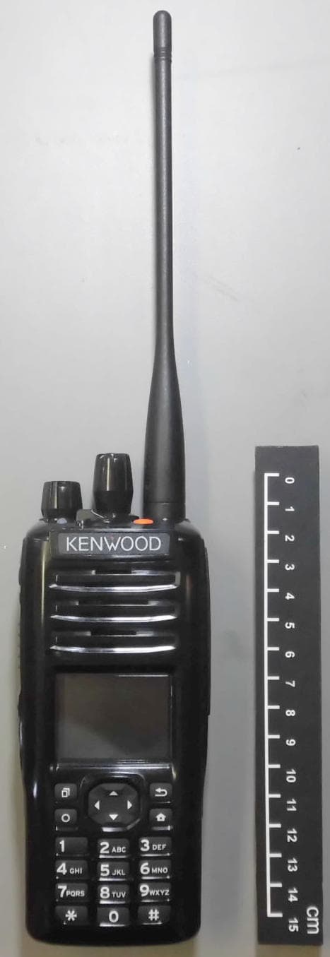
ALH442000
Jul 06, 2014Push to talk radio.
Equipment Class
DXX - Part 15 Low Power Communication Device Transmitter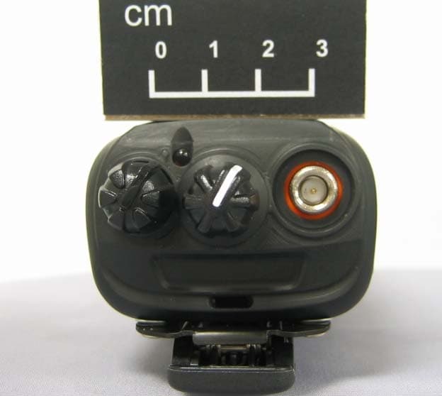
ALH443801
Dec 09, 2013UHF Digital Transceiver
Equipment Class
TNF - Licensed Non-Broadcast Transmitter Held to Face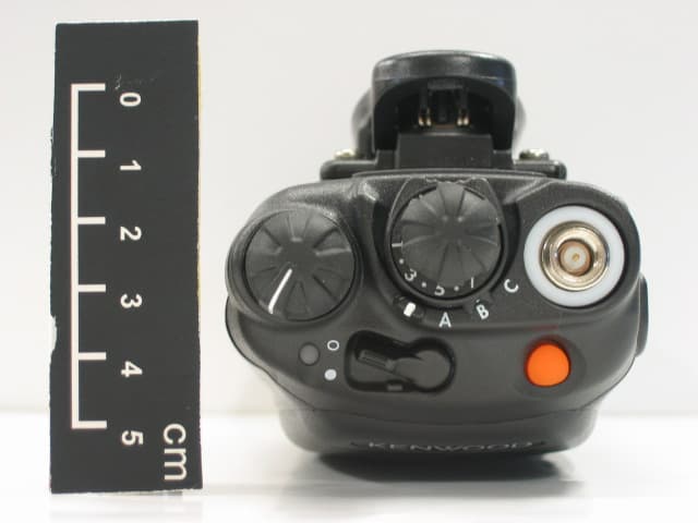
ALH468800
Oct 22, 2013PORTABLE LMR RADIO
Equipment Class
TNF - Licensed Non-Broadcast Transmitter Held to Face
ALH443700
Aug 18, 2013VHF Digital Transceiver Models NX-240-P, NX-240-K, NX-240-M, NX-240-M2, NX-240V-K
Equipment Class
TNF - Licensed Non-Broadcast Transmitter Held to Face
ALH443800
Aug 07, 2013Model NX-340 Digital Transceiver
Equipment Class
TNF - Licensed Non-Broadcast Transmitter Held to Face