ALH33063110800 MHz APCO P25 Transceiver
Kenwood USA Corporation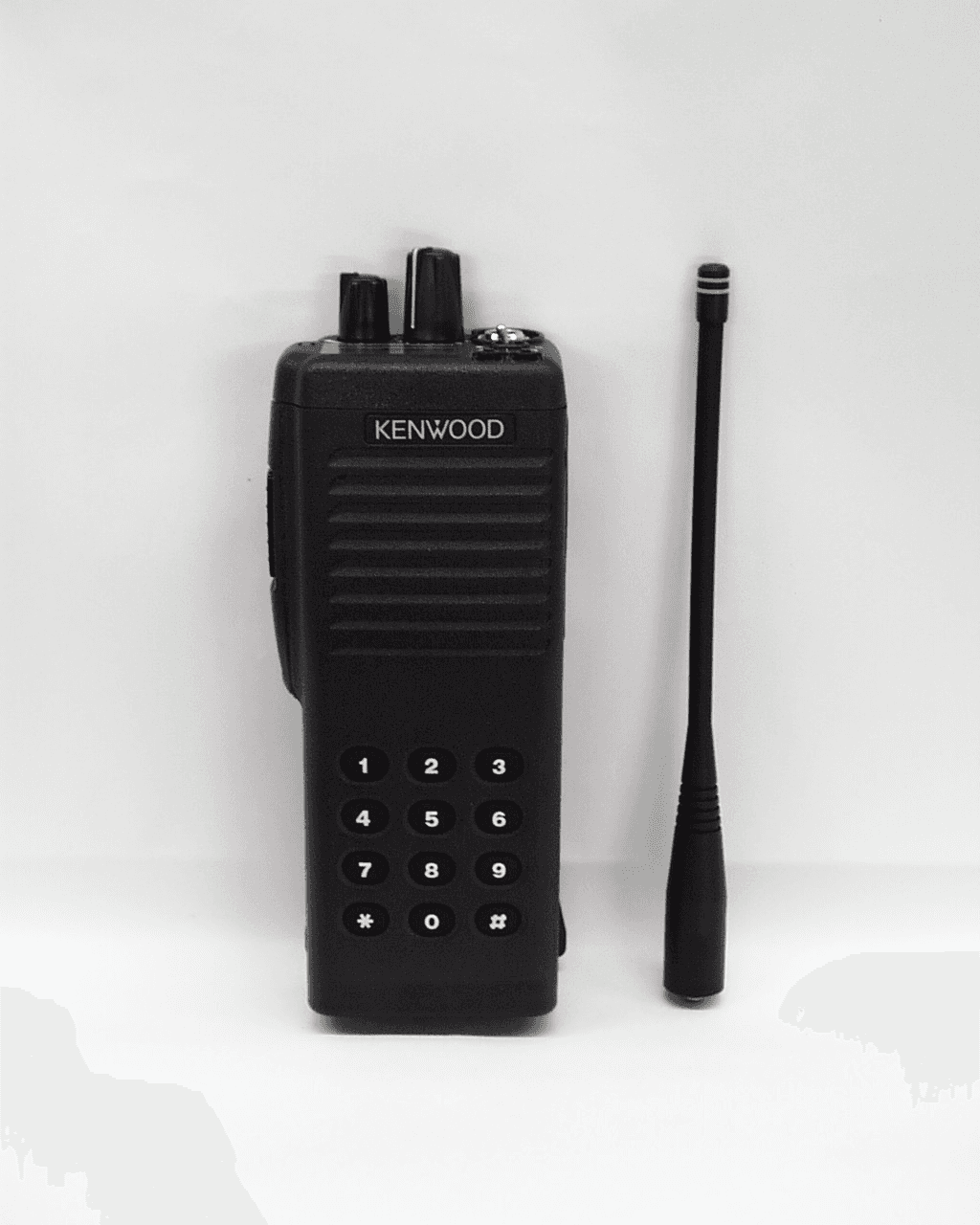
Click to zoom
Application Details
- Equipment Class
- TNF - Licensed Non-Broadcast Transmitter Held to Face
- Date of Grant
- Jun 03, 2002
- Application Purpose
- Original Equipment
- Date of Application
- Jan 02, 2002
- Equipment Note
- 800 MHz APCO P25 Transceiver
- Frequency Range
- 806.00000000 - 870.00000000
- Company
- Kenwood USA Corporation
- Country
- United States
Documents & Files
Document Text
Text extracted from the exhibit documents filed with the FCC. Open a document above to read the original.
Users Manual
KENWOOD CORPORATION FCC ID: ALH33063110 INSTRUCTION MANUAL TK-5400: THANK YOU! We are grateful you chose KENWOOD for your land mobile radio applications. We believe this easy-to-use transceiver will provide dependable communications to keep personnel operating at peak efficiency. KENWOOD transceivers incorporate the latest in advanced technology. As a result, we feel strongly that you will be pleased with the quality and features of this product. NOTICES TO THE USER WARNING: GOVERNMENT LAW PROHIBITS THE OPERATION OF UNLICENSED RADIO TRANSMITTERS WITHIN THE TERRITORIES UNDER GOVERNMENT CONTROL. ILLEGAL OPERATION IS PUNISHABLE BY FINE OR IMPRISONMENT OR BOTH. REFER SERVICE TO QUALIFIED TECHNICIANS ONLY. DO NOT OPERATE YOUR TRANSCEIVER IN EXPLOSIVE ATMOSPHERES (GASES, DUST, FUMES, ETC.). TURN OFF YOUR TRANSCEIVER WHILE TAKING ON FUEL, OR WHILE PARKED IN GASOLINE SERVICE STATIONS. SAFETY: It is important that the operator is aware of and understands hazards common to the operation of any transceiver. WARNING: EXPLOSIVE ATMOSPHERES (GASES, DUST, FUMES, etc.) Turn off your transceiver while taking on fuel, or while parked in gasoline service stations. One or more of the following statements may be applicable: FCC WARNING This equipment generates or uses radio frequency energy. Changes or modifications to this equipment may cause harmful interference unless the modifications are expressly approved in the instruction manual. The user could lose the authority to operate this equipment if an unauthorized change or modification is made. INFORMATION TO THE DIGITAL DEVICE USER REQUIRED BY THE FCC This equipment has been tested and found to comply with the limits for a Class B digital device, pursuant to Part 15 of the FCC Rules. These limits are designed to provide reasonable protection against harmful interference in a residential installation. This equipment generates, uses and can generate radio frequency energy and, if not installed and used in accordance with the instructions, may cause harmful interference to radio communications. However, there is no guarantee that the interference will not occur in a particular installation. If this equipment does cause harmful interference to radio or television reception, which can be determined by turning the equipment off and on, the user is encouraged to try to correct the interference by one or more of the following measures: Reorient or relocate the receiving antenna. Increase the separation between the equipment and receiver. Connect the equipment to an outlet on a circuit different from that to which the receiver is connected. Consult the dealer for technical assistance. KENWOOD CORPORATION FCC ID: ALH33063110 ATTENTION (U.S.A. Only): The RBRC Recycle seal found on KENWOOD nickel-cadmium (Ni-Cd) battery packs indicates KENWOOD ’s voluntary participation in an industry program to collect and recycle Ni-Cd batteries after their operating life has expired. The RBRC program is an alternative to disposing Ni-Cd batteries with your regular refuse or in municipal waste streams, which is illegal in some areas. For information on Ni-Cd battery recycling in your area, call (toll free) 1-800-8-BATTERY (1-800-822-8837). KENWOOD ’s involvement in this program is part of our commitment to preserve our environment and conserve our natural resources. UNPACKING AND CHECKING EQUIPMENT Note: The following unpacking instructions are for use by your KENWOOD dealer, an authorized KENWOOD service facility, or the factory. Carefully unpack the transceiver. We recommend that you identify the items listed in the following table before discarding the packing material. If any items are missing or have been damaged during shipment, file a claim with the carrier immediately. Accessories Quantity Item Part Number K K2 Instruction Manual B62 – 1606 - *0 1 1 Warranty Card B46 - 0470 -*0 1 1 Belt Hook J29 – 0652 - *5 1 1 Screw Set N99 - 2004 - *5 1 1 Dressing Plate B03 – 0594 - *4 1 1 Cap B09 - 0363 - *3 1 1 Stopper D32 – 0421 - *4 1 1 KENWOOD CORPORATION FCC ID: ALH33063110 Installing/ Removing the Optional Battery Pack PREPARATION The battery pack is not charged at the factory; charge it before use. CAUTION: DO NOT RECHARGE THE BATTERY PACK IF IT IS ALREADY FULLY CHARGED. DOING SO MAY CAUSE THE LIFE OF THE BATTERY PACK TO SHORTEN OR THE BATTERY PACK MAY BE DAMAGED. AFTER RECHARGING THE BATTERY PACK, DISCONNECT IT FROM THE CHARGER. IF THE CHARGER POWER IS RESET (TURNED ON AFTER BEING TURNED OFF), RECHARGING WILL START AGAIN AND THE BATTERY PACK WILL BECOME OVERCHARGED. DO NOT SHORT THE BATTERY TERMINALS OR DISPOSE OF THE BATTERY BY FIRE. NEVER ATTEMPT TO REMOVE THE CASING FROM THE BATTERY PACK. 1 Match the four grooves of the battery pack with the corresponding guides on the back of the transceiver. 2 Slide the battery pack along the back of the transceiver until the release latch on the base of the transceiver locks. 3 To remove the battery pack, pull back on the release latch and slide the pack away from the transceiver. KENWOOD CORPORATION FCC ID: ALH33063110 Installing the Antenna Screw the antenna into the connector on the top of the transceiver by holding the antenna at its base and turning it clockwise until secure. Installing the Belt Clip If necessary, attach the belt clip using the two supplied 3 x 6 mm screws. Note: If the belt clip is not installed, its mounting location may get hot during continuous transmission or when left sitting in a hot environment. Installing the Cap over the Universal Connector If you are not using the optional KMC-25 speaker/ microphone, install the cap over the universal connector using the supplied 4 x 6 mm screw. Note: To keep the transceiver water resistant, you must cover the universal connector with the cap or the speaker/ microphone connector. KENWOOD CORPORATION FCC ID: ALH33063110 Installing the Optional KMC-25 Speaker/ Microphone 1 Insert the guide of the speaker/ microphone connector into the groove of the universal connector. 2 Secur…
Text truncated - open the document above for the full version.
Users Manual
(The following will be placed in the Instruction Manual) MANDATORY SAFETY INSTRUCTIONS TO INSTALLERS & USERS Use only manufacturer or dealer supplied antenna. Antenna Minimum Safe Distance: 2.5 cm from face, 1.2 cm from body. Antenna Gain: zero dBd referenced to a dipole. The Federal Communications Commission has adopted a safety standard for human exposure to RF (Radio Frequency) energy which is below the OSHA (Occupational Safety and Health Act) limits. Antenna Mounting:The antenna supplied by the manufacturer or radio dealer must not be mounted at a location such that during radio transmission, any person or persons can come closer than the above indicated minimum safe distance to the antenna i.e. 2.5 cm from face, 1.2 cm from body. To comply with current FCC RF Exposure limits, the antenna must be installed at or exceeding the minimum safe distance shown above, and in accordance with the requirements of the antenna manufacturer or supplier. Base Station Installation: The antenna should be fixed-mounted on an outdoor permanent structure. RF Exposure compliance must be addressed at the time of installation. Antenna Substitution:Do not substitute any antenna for the one supplied or recommended by the manufacturer or radio dealer. You may be exposing person or persons to excess radio frequency radiation. You may contact your radio dealer or the manufacturer for further instructions. WARNING: Maintain a separation distance from the antenna to a person(s) of at least 2.5 cm from face, 1.2 cm from body. You, as the qualified end-user of this radio device must control the exposure conditions of bystanders to ensure the minimum separation distance (above) is maintained between the antenna and nearby persons for satisfying RF Exposure compliance. The operation of this transmitter must satisfy the requirements of Occupational/Controlled Exposure Environment, for work-related use. Transmit only when person(s) are at least the minimum distance from the properly installed, externally mounted antenna.
Attestation Statements
August 27, 2001 Federal Communications Commission Authorization & Evaluation Division 7435 Oakland Mills Road Columbia, MD 21046 Gentlemen: Reference: This equipment meets the requirements of FCC Rules, Parts 90.203(e) and (g) as applicable. Programming of this product’s transmit frequencies can be performed ONLY by the manufacturer or by service or maintenance personnel. The operator cannot program transmit frequencies using the equipment’s external operation controls. Sincerely, Kenwood Communications Corporation Joel E. Berger Joel. E. Berger Staff Engineer Kenwood Communications Corporation Research & Development Department Corporate Headquarters Kenwood Communications Corporation 3975 Johns Creek Court, Suite 300 Suwanee, GA 30024 678-474-4700 Distribution: 2201 E. Dominguez St. Long Beach, CA 90810 (310) 639-4200 Mailing Address: P.O. Box 22745 Long Beach, CA 90801-5745
Attestation Statements
1/3/02 Federal Communications Commission EQUIPMENT APPROVAL SERVICES P.O. Box 358315 Pittsburgh, PA 15251-5315 Attention: Authorization and Evaluation Division Reference: FCC ID: ALH33063110 Model TK-5400 Dear Sir: Pursuant to Sections 0.457(d)(1)(ii) and 0.459 of the Commission's Rules, the Applicant hereby requests confidential treatment of some of the information accompanying this Application, as listed below: Schematic Diagrams Circuit Description Internal Photographs Semiconductor/Active Device List These materials contain trade secrets and proprietary information not customarily released to the public. The public disclosure of these matters might be harmful to the Applicant and provide unjustified benefits to its competitors. The Applicant understands that pursuant to Rule 0.457 (d)(1)(ii), disclosure of the Application and all accompanying documentation will not be made before the date of Grant for the Application. Sincerely yours, Morton Flom, P. Eng.
Block Diagram
MIC HSD Selector POW FC GRN, RED, BKLIT EXTAFC, INTAFC AMPSW, N/CSW 5TC, 5TBC, 5CC, 5RC TA, BUSY, (W/N) VOLUME Control Unit (X53-393) 5R RSSI BKLIT B+ 5C 5M 5R 5TB 5TC TOP Key LAMP TC75W51FU TC75W51FU BSP1 BSP0 44SP12BA LCD ANT SW LPF AMP AMP AMP AMP x 2 T/R SW AMP VCO PLL SA7026 VCXO ADC TLV2544 DSP TMS320VC5410 JTAG I/F TCXO CODEC AK4550 AMP AMP AMP SUM AMP 455kHz IF AD607 AMP 2SC5108 2SC5108 x 2 2SC5108 2SC4988 DC SW 5TB MIX DC SW DC SW Curr. DET Protect B+ 2SC4617 HN1L02FU DTC114EE 2SK1824 5T POW NJM2904 LPF BPF BPF 16.8MHz TONE CP DP LE Ripple Filter 5C MOD TA MA2S077 x 2 2SC4617, 1SS389 BATT 7.5V HVU131 MA2S077 x 2 SB SW 5V Reg 5V Reg 1SR154 TPC6102 2SK1830 1SS361 XC6204B502 SW SW Lamp Reg 5RC 3.3V Reg SSM3J05 5CC 5TBC Shift Register EE PROM Flash ROM Reset SW Universal Connector EMC 5M TXD RTS SSW MSW/CTS PTT RXD REM DSR Surge Protect NNCD6.8G 33D 25D 33A Volt DET AMP SP+, SP- LCD Driver LC73824W LED Toggle 2SC4617 2SB1132 2SC4617 MA2S111 MOD TONE AMP HPI Display Unit (X53-393) TGL KEY2 Q6, Q7 LAMP TXLED BLED CE CL DI CH_A CH_B CH_C CH_D 33D SB BU4094 x 2 INT SP Protect PST3527U 2SJ347 DTC144EE TC75W51FU TC75W51FU MBM29LV800B90 AT24256N XC61CC4202 VOL 33A AF SUM TC75W51FU TXRX Unit (X57-653) AFAMP TDA7053 PTT PF Key Reg SB 2SB798 2SC4617 DTZ3.9 AMPSW SP+, SP- SW AF MUTE EXTAFC INTAFC 2SK1824 x 3 AMP NJM2904 MUTE INTMICMain INTMIC Cancel N/CSW UMC4 MIC 12 Key Matrix Q6, Q7 5M IF1=44.85MHz FUSE TOP Scan MA2S111 KEY1 KEY2 PTT 5M, MUTE AMPSW, SB N/CSW INTAFC EXTAFC LAMP LAMP AMP AMP x 2 2SK3391 2SK3390 x 2 3.3 → 5V TC7SET08 x 3 BPF MUTE XC6204B502 5V Reg XC6204B502 33D SW 5T XC6204B332 TXLED RED BLED GRN XC6365D103M TPC6102 HRB0502A XC6204B332 KM4100 44.395MHz 2SK1215 SFPC455E OSC 2SC5108 GN2011 SB SW Switch Reg 3.3V Reg 2.5V Reg 33D 25D 33A 2SC4617 Protect DA221 1SS389 S/R IMN10 x 4 MA2S111 BU4094*2 Port Scan IMN10 TC7W04FU TC7SH08FU x 3 CLK DATA KES MAN_D OPPTT TCONT 3 pole 2 pole SFPC455E Key Scan 3SK274 XC6204B252 SW XC61CN5002 IF2=455kHz BUFF SW SB BATT TC74WH32 x3 TC74VHCT541 HN1L02FU EXSP, TGL SELF, PSW, UL CH_A, CH_B CH_C, CH_D CP, DP, LE SOE, PWR 2SK1830 5R KEY1, KEY2 RXD, CTS DSR 5V → 3.3V CLK, DAT LD, STB, KES LCDCS TXD, RTS 3.3V → 5V uCOM M16C RSSI, CV VOL, BATT TEMP A/D SW HN1L02FU SOE CLK DAT STB SCL SDA 12.288MHz BUFF TC7W04FU EMC MSW/CTS DAC M62364 CLK DAT LD TC75W51FU 33D Protect PTT MAS2S111 33D 5M B+ 5TB 33AR 2SJ243 SW 33AR 5RC BUFF CV TC75W51FU PWSW PWR SW PSW 2SK1830 MUTE MM 2SK1830 MIC AF SP+ SP- 5R UL TC75W51FU SQ EDT 2SC4617 SQL TC75W51FU SW TC7W66FU SW 33D AGC SSM3J05 Block Diagram KENWOOD Confidential & Proprietary
Cover Letter(s)
August 27, 2001 Federal Communications Commission Authorization & Evaluation Division 7435 Oakland Mills Road Columbia, MD 21046 Gentlemen: This letter will authorize the appointment of MORTON FLOM, P. Eng. and/or M. Flom Associates, Inc. to act as our agent in all FCC matters. This appointment is effective until you are otherwise notified by us. This is to advise that we are in full compliance with the Anti-Drug Abuse Act. The application is not subject to a denial of federal benefits pursuant to section 5301 of the Anti-Drug Abuse Act of 1988, 21 USC 8.62, and no party to the application is subject to a denial of federal benefits pursuant to that section. Sincerely, Kenwood Communications Corporation Joel E. Berger Joel E. Berger Staff Engineer Research & Development Department Kenwood Communications Corporation Corporate Headquarters Kenwood Communications Corporation 3975 Johns Creek Court, Suite 300 Suwanee, GA 30024 678-474-4700 Distribution: 2201 E. Dominguez St. Long Beach, CA 90810 (310) 639-4200 Mailing Address: P.O. Box 22745 Long Beach, CA 90801-5745
Parts List/Tune Up Info
FCC ID:ALH33063110 1.0. PTT + [Side PF2] + Power On PTT off [Side PF2] off 1.1. TXF (TX Frequency Adjustment) @815.50MHz Press PTT and adjust TX frequency to 815.50MHz by 【Top PF1】、【Top PF2】keys. Equipment: Modulation Analyzer (HP8901B) In high accuracy mode by function 7.1+Special 1.2. PWR (RF Power Hi Adjustment) @815.50MHz Press PTT and adjust TX output power to +34.8dBm by 【Top PF1】、【Top PF2】keys. Equipment: Modulation Analyzer (HP8901B) For getting high measurement response, taking low accuracy by function 7.0+Special Adjustment accuracy is about 0.030(W/digit) around 3W. 1.2.1 PWR_L (RF Power Hi @L-Edge Adjustment) @806.05MHz 1.2.2 PWR_C (RF Power Hi @Center Adjustment) @815.50MHz 1.2.3 PWE_H (RF Power Hi @H-Edge Adjustment) @824.90MHz 1.3. tPWR (RF Power Hi Talk Around Mode Adjustment) @860.50MHz Press PTT and adjust TX output power to +34.8dBm by 【Top PF1】、【Top PF2】keys. Equipment: Modulation Analyzer (HP8901B) 1.3.1 PWR_tL (RF Power Hi TA @L-Edge Adjustment) @851.05MHz 1.3.2 PWR_tC (RF Power Hi TA @Center Adjustment) @860.50MHz 1.3.3 PWR_tH (RF Power Hi TA @H-Edge Adjustment) @869.90MHz 1.4. PWR_Lo (RF Power Lo Adjustment) @815.50MHz Press PTT and adjust TX output power to +30.0dBm by 【Top PF1】、【Top PF2】keys. Equipment: Modulation Analyzer (HP8901B) Adjustment accuracy is about 0.025(W/digit) around 1W. 1.5. PWR+tLo (RF Power Lo Talk Around Mode Adjustment) @860.50MHz Press PTT and adjust TX output power to +30.0dBm by 【Top PF1】、【Top PF2】keys. Equipment: Modulation Analyzer (HP8901B) 1.6. MIC (MIC sensitivity adjustment) Set at a constant value (129) by 【Top PF1】、【Top PF2】keys. 1.7. BAL (VCO/VCXO Deviation Balance Adjustment) @815.50MHz Press PTT and adjust Output waveform(100Hz) to get a square waveform by 【Top PF1】、 【Top PF2】keys. Equipment: Modulation Analyzer (HP8901B) LPF = 3kHz, HPF = OFF, De-Emphasis = OFF Oscilloscope 1.8. BAL_t (DQT Balance Adjustment for Talk Around Mode) @860.50MHz Same as 1.7 BAL 1.9. HDVA (APCO Deviation Adjustment) @815.50MHz Press PTT and adjust FM Deviation to 2.827kHz by 【Top PF1】、【Top PF2】keys. Equipment: Modulation Analyzer (HP8901B) LPF = 3kHz, HPF = OFF, De-Emphasis = OFF, Detector = Peak (+/-) 1.9.1 HDVA_L (APCO Deviation Adjustment @L-Edge) @806.05MHz 1.9.2 HDVA_H (APCO Deviation Adjustment @H-Edge) @824.90MHz 1.10. HDVA_t (APCO Deviation Adjustment for Talk Around Mode) @860.50MHz Same as HDVA 1.10.1 HDVA_t_L (APCO Deviation Adjustment for Talk Around Mode @L-Edge) @851.05MHz 1.10.2 HDVA_t_H (APCO Deviation Adjustment for Talk Around Mode @H-Edge) @869.90MHz 1.11. FMDV (FM Wide MAX Deviation Adjustment) @815.50MHz Press PTT and adjust FM Deviation to 4.00kHz by 【Top PF1】、【Top PF2】keys. Equipment: Modulation Analyzer (HP8901B) LPF = 15kHz, HPF = OFF, De-Emphasis = OFF, Detector = Peak (+/-) FCC ID:ALH33063110 Audio Generator MIC Input = 150 mV, 1kHz 1.12. FMDV_t (FM Wide MAX Deviation Adjustment for Talk Around Mode) @860.50MHz Same as 1.11 FMDV 1.13. NMDV (FM NPSPAC MAX Deviation Adjustment) @815.50MHz Press PTT and adjust FM Deviation to 3.20kHz by 【Top PF1】、【Top PF2】keys. Equipment: Modulation Analyzer (HP8901B) LPF = 15kHz, HPF = OFF, De-Emphasis = OFF, Detector = Peak (+/-) Audio Generator MIC Input = 150 mV, 1kHz 1.14. NMDV_t (FM NPSPAC MAX Deviation Adjustment for Talk Around Mode) @860.50MHz Same as 1.13 NMDV 1.15. QTDV (QT Deviation Adjustment) @815.50MHz Press PTT and adjust FM Deviation to 0.75kHz by 【Top PF1】、【Top PF2】keys. Equipment: Modulation Analyzer (HP8901B) LPF = 3kHz, HPF = OFF, De-Emphasis = OFF, Detector = Peak±)/2 1.16. QTDV_t (QT Deviation Adjustment for Talk Around Mode) @860.50MHz Same as 1.15 QTDV 1.17. DQDV (DQT Deviation Adjustment) @815.50MHz Press PTT and adjust FM Deviation to 0.75kHz by 【Top PF1】、【Top PF2】keys. Equipment: Modulation Analyzer (HP8901B) LPF = 3kHz, HPF = OFF, De-Emphasis = OFF, Detector = Peak+, Peak Hold 1.18. DQDV_t (DQT Deviation Adjustment for Talk Around Mode) @860.50MHz Same as 1.17 DQDV 1.19. DTDV (DTMF Deviation Adjustment) @815.50MHz Press PTT and adjust FM Deviation to 3.00kHz by 【Top PF1】、【Top PF2】keys. Equipment: Modulation Analyzer (HP8901B) LPF = 15kHz, HPF = OFF, De-Emphasis = OFF, Detector = Peak (+/-) 1.20. DTDV_t (DTMF Deviation Adjustment for Talk Around Mode) @860.50MHz Same as 1.19 DTDV 1.21 SQ_O (Squelch Threshold Level Adjustment and RSSI Reference Level Writing) Input RF signal corresponding to 12dBSINAD-3dB from SSG, and adjust the digit number so that Squelch could be opened by 【Top PF1】、【Top PF2】keys. Equipment: SSG(860.5MHz) 1.22 LRSI (RSSI Lo Level Writing) Input RF signal corresponding to 12dBSINAD from SSG, and press orange key to memorize the digit number. Equipment: SSG(860.5MHz) 1.23 SQ_T (Squelch Tight Level Adjustment) Input RF signal corresponding to 12dBSINAD+5dB from SSG, and adjust the digit number so that Squelch could be opened by 【Top PF1】、【Top PF2】keys. Equipment: SSG(860.5MHz) 1.24 HRSI (RSSI Hi Level Writing) Input RF signal –70dBm from SSG, and press orange key to memorize the digit number. Equipment: SSG(860.5MHz) 1.25 BATT (Battery Warning Level Writing) Set DC Power Supply at 6.2V and press orange key to memorize the digit number.
RF Exposure Info
CELLTECH RESEARCH INC. Test Report S/N: 122001-190ALH 1955 Moss Court, Kelowna Test Dates: December 20, 2001 B.C. Canada V1Y 9L3 FCC SAR Evaluation _____________________________________________________________________________________________________________ © 2001 Celltech Research Inc. CERTIFICATE OF COMPLIANCE SAR EVALUATION Celltech Research Inc. declares under its sole responsibility that this device was found to be in compliance with the Specific Absorption Rate (SAR) RF exposure requirements specified in OET Bulletin 65, Supplement C, Edition 01-01 (Occupational/Controlled Exposure), and was tested in accordance with the appropriate measurement standards, guidelines, and recommended practices specified in American National Standards Institute C95.1-1992. I attest to the accuracy of data. All measurements were performed by me or were made under my supervision and are correct to the best of my knowledge and belief. I assume full responsibility for the completeness of these measurements and vouch for the qualifications of all persons taking them. This test report shall not be reproduced partially, or in full, without the prior written approval of Celltech Research Inc. The results and statements contained in this report pertain only to the device(s) evaluated. Shawn McMillen General Manager Celltech Research Inc. Test Lab: CELLTECH RESEARCH INC. Testing and Engineering Lab 1955 Moss Court Kelowna, B.C. Canada V1Y 9L3 Phone: 250 - 860-3130 Fax: 250 - 860-3110 Toll Free: 1-877-545-6287 e-mail: [email protected] web site: www.celltechlabs.com Applicant Information: KENWOOD COMMUNICATIONS CORP. 3975 Johns Creek Court, Suite 300 Suwanee, GA 30024 FCC Rule Part(s): 2.1093; ET Docket 96-326 FCC ID: ALH33063110 Model(s): TK-5400 EUT Type(s): Portable FM PTT Radio Transceiver Modulation: FM Tx Frequency Range(s): 806 - 824 MHz Rated RF Conducted Power: 3 Watts Antenna Type(s): 1/2 Wave Whip Antenna Battery Type(s): 7.2 VDC NiMH Battery (KNB-22N) CELLTECH RESEARCH INC. Test Report S/N: 122001-190ALH 1955 Moss Court, Kelowna Test Dates: December 20, 2001 B.C. Canada V1Y 9L3 FCC SAR Evaluation _____________________________________________________________________________________________________________ © 2001 Celltech Research Inc. TABLE OF CONTENTS 1.0 INTRODUCTION.................................................................. 1 2.0 DESCRIPTION OF EQUIPMENT UNDER TEST......................... 1 3.0 SAR MEASUREMENT SYSTEM ............................................. 2 4.0 MEASUREMENT SUMMARY.................................................. 3-4 5.0 DETAILS OF SAR EVALUATION............................................ 5 6.0 EVALUATION PROCEDURES................................................. 6 7.0 SYSTEM VALIDATION......................................................... 7 8.0 TISSUE PARAMETERS.......................................................... 7 9.0 SIMULATED TISSUES........................................................... 8 10.0 SAR SAFETY LIMITS ........................................................... 8 11.0 ROBOT SYSTEM SPECIFICATIONS....................................... 9 12.0 PROBE SPECIFICATION....................................................... 10 13.0 PLANAR PHANTOM.............................................................. 10 14.0 DEVICE HOLDER................................................................. 10 15.0 TEST EQUIPMENT LIST........................................................ 11 16.0 MEASUREMENT UNCERTAINTIES........................................ 12 17.0 REFERENCES...................................................................... 13 APPENDIX A - SAR MEASUREMENT DATA........................................ 14 APPENDIX B - DIPOLE VALIDATION................................................ 15 APPENDIX C - DIPOLE CALIBRATION............................................. 16 APPENDIX D - PROBE CALIBRATION............................................... 17 APPENDIX E - SAR SENSITIVTIES.................................................... 18 APPENDIX F - SAR AND EUT PHOTOGRAPHS.................................... 19 CELLTECH RESEARCH INC. Test Report S/N: 122001-190ALH 1955 Moss Court, Kelowna Test Dates: December 20, 2001 B.C. Canada V1Y 9L3 FCC SAR Evaluation _____________________________________________________________________________________________________________ © 2001 Celltech Research Inc. KENWOOD FCC ID: ALH33063110 (Model: TK-5400) 1 Portable FM PTT Radio Transceiver (806-824MHz) 1.0 INTRODUCTION This measurement report shows that the KENWOOD COMMUNICATIONS CORP. Model: TK-5400 Portable FM PTT Radio Transceiver FCC ID: ALH33063110 complies with FCC Part 2.1093, ET Docket 96-326 Rules for mobile and portable devices (controlled exposure). The test procedures, as described in American National Standards Institute C95.1-1992 (see reference [1]), and FCC OET Bulletin 65, Supplement C, Edition 01-01 (see reference [2]) were employed. A description of the product and operating configuration, detailed summary of the test results, methodology and procedures used in the evaluation, equipment used, and the various provisions of the rules are included within this test report. 2.0 DESCRIPTION OF EQUIPMENT UNDER TEST (EUT) FCC Rule Part(s) 2.1093; ET Docket 96.326 EUT Type Portable FM PTT Radio Transceiver FCC ID ALH33063110 Model(s) TK-5400 Serial No. Pre-production Modulation FM Tx Frequency Range (MHz) 806 - 824 MHz Rated RF Conducted Output Power 3 Watts Antenna Type(s) 1/2 Wave Whip Antenna Antenna Length 17.5 cm Body-Worn Accessories Speaker-Microphone Plastic Belt-Clip Battery Type(s) 7.2 VDC 2100mAh NiMH (KNB-22N) CELLTECH RESEARCH INC. Test Report S/N: 122001-190ALH 1955 Moss Court, Kelowna Test Dates: December 20, 2001 B.C. Canada V1Y 9L3 FCC SAR Evaluation _____________________________________________________________________________________________________________ © 2001 Celltech Research Inc. KENWOOD FCC ID: ALH33063110 (Model: TK-5400) 2 P…
Text truncated - open the document above for the full version.
RF Exposure Info
Celltech Research Inc. 1955 Moss Court, Kelowna, B.C. Canada V1Y 9L3 Tel. 250-860-3130 • Fax. 250-860-3110 • e-mail: [email protected] www.celltechlabs.com March 1, 2002 Federal Communications Commission Equipment Approval Services 7435 Oakland Mills Road Columbia, MD 21046 Attn: Steve Dayhoff SUBJECT: Kenwood Communications Corporation FCC ID: ALH33063110 731 Confirmation No.: EA172230 Correspondence Ref. No.: 22120 Dear Steve: On behalf of Kenwood Communications Corporation is an amendment in response to item 4 of your e-mail dated February 28, 2002 requesting additional information for the subject application. 1. Please see item f on page 6 of the SAR report for justification of the probe conversion factors used. The probe conversion factors differ between Celltech and SPEAG because they are different probes. The system manufacturer uses their own E-field probe (SN:1507) for the system verification, and we use our own probe (SN:1590 manufactured by SPEAG). This explains the difference between the probe conversion factors. If you have any further questions regarding the above, please do not hesitate to contact me. Sincerely, Shawn McMillen General Manager Celltech Research Inc. Testing & Engineering Lab cc: Kenwood Communications Corporation M. Flom Associates
Test Report
FCC ID: ALH33063110 MFA p01b0006, d01c0040 Date of Report: Date of Submission: December 19, 2001 January 3, 2002 Federal Communications Commission Via: Electronic Filing Attention: Authorization & Evaluation Division Applicant: Kenwood Communications Corporation Equipment: TK-5400 FCC ID: ALH33063110 FCC Rules: 90, Confidentiality Gentlemen: On behalf of the Applicant, enclosed please find Application Form 731, Engineering Test Report and all pertinent documentation, the whole for approval of the referenced equipment as shown. Filing fees are attached. We trust the same is in order. Should you need any further information, kindly contact the writer who is authorized to act as agent. Sincerely yours, Morton Flom, P. Eng. enclosure(s) cc: Applicant MF/cvr FCC ID: ALH33063110 MFA p01b0006, d01c0040 LIST OF EXHIBITS (FCCCERTIFICATION(TRANSMITTERS) - REVISED 9/28/98) APPLICANT: Kenwood Communications Corporation FCC ID: ALH33063110 BY APPLICANT: 1. LETTER OF AUTHORIZATION x 2. IDENTIFICATION DRAWINGS, 2.1033(c)(11) xLABEL xLOCATION OF LABEL xCOMPLIANCE STATEMENT xLOCATION OF COMPLIANCE STATEMENT 3. PHOTOGRAPHS, 2.1033(c)(12) x 4. DOCUMENTATION: 2.1033(c) (3) USER MANUAL x (9) TUNE UP INFO x (10) SCHEMATIC DIAGRAM x (10) CIRCUIT DESCRIPTION x BLOCK DIAGRAM x PARTS LIST x ACTIVE DEVICES x 5. PART 90.203(e) & (g) ATTESTATION x 6. CONFIDENTIALITY REQUEST: 0.457 and 0.459 x 7. SAR Report by Celltech Research Inc. x BY M.F.A. INC. A. TESTIMONIAL & STATEMENT OF CERTIFICATION B. STATEMENT OF QUALIFICATIONS FCC ID: ALH33063110 MFA p01b0006, d01c0040 TRANSMITTER CERTIFICATION of FCC ID: ALH33063110 MODEL: TK-5400 to FEDERAL COMMUNICATIONS COMMISSION Rule Part(s) 90, Confidentiality DATE OF REPORT: December 19, 2001 ON THE BEHALF OF THE APPLICANT: Kenwood Communications Corporation AT THE REQUEST OF : P.O. 41640 Kenwood Communications Corporation Technology Park at Johns Creek 3975 Johns Creek Court #300 Suwanee, GA 30024 Attention of: Joel E. Berger, Research & Development [email protected] (678) 474-4722; FAX: -4731 SUPERVISED BY: Morton Flom, P. Eng. FCC ID: ALH33063110 MFA p01b0006, d01c0040 THE APPLICANT HAS BEEN CAUTIONED AS TO THE FOLLOWING: 15.21 INFORMATION TO USER. The users manual or instruction manual for an intentional radiator shall caution the user that changes or modifications not expressly approved by the party responsible for compliance could void the user's authority to operate the equipment. 15.27(a) SPECIAL ACCESSORIES. Equipment marketed to a consumer must be capable of complying with the necessary regulations in the configuration in which the equipment is marketed. Where special accessories, such as shielded cables and/or special connectors are required to enable an unintentional or intentional radiator to comply with the emission limits in this part, the equipment must be marketed with, i.e. shipped and sold with, those special accessories. However, in lieu of shipping or packaging the special accessories with the unintentional or intentional radiator, the responsible party may employ other methods of ensuring that the special accessories are provided to the consumer, without additional charge. Information detailing any alternative method used to supply the special accessories for a grant of equipment authorization or retained in the verification records, as appropriate. The party responsible for the equipment, as detailed in § 2.909 of this chapter, shall ensure that these special accessories are provided with the equipment. The instruction manual for such devices shall include appropriate instructions on the first page of text concerned with the installation of the device that these special accessories must be used with the device. It is the responsibility of the user to use the needed special accessories supplied with the equipment. FCC ID: ALH33063110 MFA p01b0006, d01c0040 TABLE OF CONTENTS RULEDESCRIPTIONPAGE . Test Report 1 2.1033(c) General Information Required 2 2.1033(c)(14) Rule Summary 6 . St…
Text truncated - open the document above for the full version.
Contact Information
Applicant
Angelina Seay(Regulatory Support Engineer)
Technical Contact
M. Flom Associates, IncMorton Flom
[email protected]480 926 3100
3356 N. San Marcos Pl., Suite 107 · Chandler, Arizona · United States
Non-Technical Contact
M. Flom Associates, Inc.Morton Flom
[email protected]480 926 3100
Test Firm
M. Flom Associates, Inc.Morton Flom
Technical Specifications
| # | Rule Parts | Frequency Range | Power Output | Emission | Tolerance |
|---|---|---|---|---|---|
| 1 | 9 | 806 MHz - 870 MHz | 3.11 W | 14K0F3E | 1.5 ppm |
Other Applications from Kenwood USA Corporation
ALH442000
Jul 06, 2014Push to talk radio.
Equipment Class
DXX - Part 15 Low Power Communication Device Transmitter
ALH443801
Dec 09, 2013UHF Digital Transceiver
Equipment Class
TNF - Licensed Non-Broadcast Transmitter Held to Face
ALH468800
Oct 22, 2013PORTABLE LMR RADIO
Equipment Class
TNF - Licensed Non-Broadcast Transmitter Held to Face
ALH443700
Aug 18, 2013VHF Digital Transceiver Models NX-240-P, NX-240-K, NX-240-M, NX-240-M2, NX-240V-K
Equipment Class
TNF - Licensed Non-Broadcast Transmitter Held to Face
ALH443800
Aug 07, 2013Model NX-340 Digital Transceiver
Equipment Class
TNF - Licensed Non-Broadcast Transmitter Held to Face