ALH36023110VHF FM Transceiver
Kenwood USA Corporation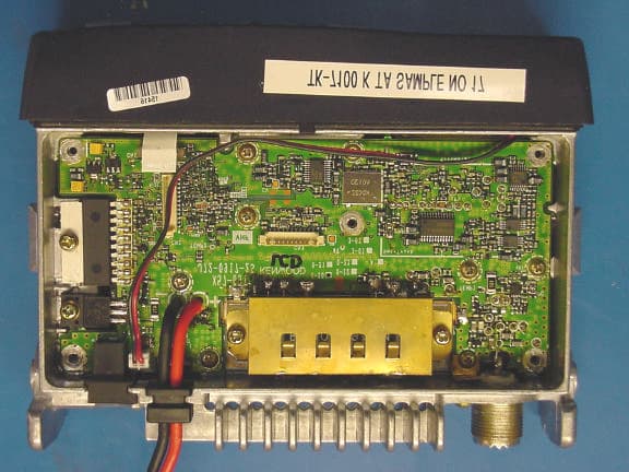
Click to zoom
Application Details
- Equipment Class
- TNB - Licensed Non-Broadcast Station Transmitter
- Date of Grant
- Oct 13, 2003
- Application Purpose
- Original Equipment
- Date of Application
- Oct 13, 2003
- Equipment Note
- VHF FM Transceiver
- Frequency Range
- 146.00000000 - 174.00000000
- Company
- Kenwood USA Corporation
- Country
- United States
Documents & Files
Document Text
Text extracted from the exhibit documents filed with the FCC. Open a document above to read the original.
Users Manual
Rhein Tech Laboratories Client: Kenwood USA Corp. 360 Herndon Parkway Model: TK-7100-1 Suite 1400 Standards: FCC Part 90/IC RSS-119 Herndon, VA 20170 Report Number: 2003162 http://www.rheintech.com FCC ID: ALH36023110 46 of 50 APPENDIX J: MANUAL Please refer to the following pages. TK-7100 INSTRUCTION MANUAL VHF FM TRANSCEIVER TK-8100 UHF FM TRANSCEIVER TK-7102H E 00 Cover02.9.30, 1:41 PM1 THANK YOU! We are grateful you chose KENWOOD for your personal mobile applications. We believe this easy-to-use transceiver will provide dependable communications to keep personnel operating at peak efficiency. KENWOOD transceivers incorporate the latest in advanced technology. As a result, we feel strongly that you will be pleased with the quality and features of this product. MODELS COVERED BY THIS MANUAL The models listed below are covered by this manual: •TK-7100:VHF FM Transceiver •TK-8100:UHF FM Transceiver PRECAUTIONS Please observe the following precautions to prevent fire, personal injury, and transceiver damage. • Do not attempt to configure the transceiver while driving; it is too dangerous. • Do not modify the transceiver for any reason. • Do not expose the transceiver to long periods of direct sunlight, nor place it near heating appliances. • Do not place the transceiver in excessively dusty, humid, or wet areas, nor on unstable surfaces. • If an abnormal odor or smoke is detected coming from the transceiver, turn OFF the power immediately. Contact your KENWOOD dealer. TK-7102H E 00002.9.30, 1:41 PM1 i NOTICES TO THE USER uGovernment law prohibits the operation of unlicensed transmitters within the territories under government control. uIllegal operation is punishable by fine and/or imprisonment. uRefer service to qualified technicians only. SAFETY: It is important that the operator is aware of, and understands, hazards common to the operation of any transceiver. uEXPLOSIVE ATMOSPHERES (GASES, DUST, FUMES, etc.) Turn OFF your transceiver while taking on fuel or while parked in gasoline service stations. Do not carry spare fuel containers in the trunk of your vehicle if your transceiver is mounted in the trunk area. uINJURY FROM RADIO FREQUENCY TRANSMISSIONS Do not operate your transceiver when somebody is either touching the antenna or standing within two to three feet of it, to avoid the possibility of radio frequency burns or related physical injury. uDYNAMITE BLASTING CAPS Operating the transceiver within 500 feet (150 m) of dynamite blasting caps may cause them to explode. Turn OFF your transceiver when in an area where blasting is in progress, or where “TURN OFF TWO-WAY RADIO” signs have been posted. If you are transporting blasting caps in your vehicle, make sure they are carried in a closed metal box with a padded interior. Do not transmit while the caps are being placed into or removed from the container. One or more of the following statements may be applicable: FCC WARNING This equipment generates or uses radio frequency energy. Changes or modifications to this equipment may cause harmful interference unless the modifications are expressly approved in the instruction manual. The user could lose the authority to operate this equipment if an unauthorized change or modification is made. INFORMATION TO THE DIGITAL DEVICE USER REQUIRED BY THE FCC This equipment has been tested and found to comply with the limits for a Class B digital device, pursuant to Part 15 of the FCC Rules. These limits are designed to provide reasonable protection against harmful interference in a residential installation. This equipment generates, uses and can generate radio frequency energy and, if not installed and used in accordance with the instructions, may cause harmful interference to radio communications. However, there is no guarantee that the interference will not occur in a particular installation. If this equipment does cause harmful interference to radio or television reception, which can be determined by turning the equipment off and on, the user is encouraged to try to correct the interference by one or more of the following measures: •Reorient or relocate the receiving antenna. •Increase the separation between the equipment and receiver. •Connect the equipment to an outlet on a circuit different from that to which the receiver is connected. •Consult the dealer for technical assistance. TK-7102H E 00i-ii02.9.30, 1:41 PM1 ii CONTENTS UNPACKING AND CHECKING EQUIPMENT ................................... 1 S UPPLIED ACCESSORIES..................................................................... 1 PREPARATION .................................................................................. 2 T OOLS REQUIRED.............................................................................. 2 POWER CABLE CONNECTION............................................................... 2 INSTALLING THE TRANSCEIVER.............................................................. 3 ORIENTATION .................................................................................... 4 F RONT PANEL................................................................................... 4 D ISPLAY............................................................................................ 5 REAR PANEL..................................................................................... 5 BASIC OPERATIONS ........................................................................ 6 S WITCHING POWER ON/ OFF ............................................................. 6 ADJUSTING THE VOLUME..................................................................... 6 SELECTING A CHANNEL....................................................................... 6 T RANSMITTING................................................................................... 6 RECEIVING........................................................................................ 6 SCAN ..........................................................................................…
Text truncated - open the document above for the full version.
Users Manual
Rhein Tech Laboratories Client: Kenwood USA Corp. 360 Herndon Parkway Model: TK-7100-1 Suite 1400 Standards: FCC Part 90/IC RSS-119 Herndon, VA 20170 Report Number: 2003162 http://www.rheintech.com FCC ID: ALH36023110 46 of 50 APPENDIX J: MANUAL Please refer to the following pages. TK-7100 INSTRUCTION MANUAL VHF FM TRANSCEIVER TK-8100 UHF FM TRANSCEIVER TK-7102H E 00 Cover02.9.30, 1:41 PM1 THANK YOU! We are grateful you chose KENWOOD for your personal mobile applications. We believe this easy-to-use transceiver will provide dependable communications to keep personnel operating at peak efficiency. KENWOOD transceivers incorporate the latest in advanced technology. As a result, we feel strongly that you will be pleased with the quality and features of this product. MODELS COVERED BY THIS MANUAL The models listed below are covered by this manual: •TK-7100:VHF FM Transceiver •TK-8100:UHF FM Transceiver PRECAUTIONS Please observe the following precautions to prevent fire, personal injury, and transceiver damage. • Do not attempt to configure the transceiver while driving; it is too dangerous. • Do not modify the transceiver for any reason. • Do not expose the transceiver to long periods of direct sunlight, nor place it near heating appliances. • Do not place the transceiver in excessively dusty, humid, or wet areas, nor on unstable surfaces. • If an abnormal odor or smoke is detected coming from the transceiver, turn OFF the power immediately. Contact your KENWOOD dealer. TK-7102H E 00002.9.30, 1:41 PM1 i NOTICES TO THE USER uGovernment law prohibits the operation of unlicensed transmitters within the territories under government control. uIllegal operation is punishable by fine and/or imprisonment. uRefer service to qualified technicians only. SAFETY: It is important that the operator is aware of, and understands, hazards common to the operation of any transceiver. uEXPLOSIVE ATMOSPHERES (GASES, DUST, FUMES, etc.) Turn OFF your transceiver while taking on fuel or while parked in gasoline service stations. Do not carry spare fuel containers in the trunk of your vehicle if your transceiver is mounted in the trunk area. uINJURY FROM RADIO FREQUENCY TRANSMISSIONS Do not operate your transceiver when somebody is either touching the antenna or standing within two to three feet of it, to avoid the possibility of radio frequency burns or related physical injury. uDYNAMITE BLASTING CAPS Operating the transceiver within 500 feet (150 m) of dynamite blasting caps may cause them to explode. Turn OFF your transceiver when in an area where blasting is in progress, or where “TURN OFF TWO-WAY RADIO” signs have been posted. If you are transporting blasting caps in your vehicle, make sure they are carried in a closed metal box with a padded interior. Do not transmit while the caps are being placed into or removed from the container. One or more of the following statements may be applicable: FCC WARNING This equipment generates or uses radio frequency energy. Changes or modifications to this equipment may cause harmful interference unless the modifications are expressly approved in the instruction manual. The user could lose the authority to operate this equipment if an unauthorized change or modification is made. INFORMATION TO THE DIGITAL DEVICE USER REQUIRED BY THE FCC This equipment has been tested and found to comply with the limits for a Class B digital device, pursuant to Part 15 of the FCC Rules. These limits are designed to provide reasonable protection against harmful interference in a residential installation. This equipment generates, uses and can generate radio frequency energy and, if not installed and used in accordance with the instructions, may cause harmful interference to radio communications. However, there is no guarantee that the interference will not occur in a particular installation. If this equipment does cause harmful interference to radio or television reception, which can be determined by turning the equipment off and on, the user is encouraged to try to correct the interference by one or more of the following measures: •Reorient or relocate the receiving antenna. •Increase the separation between the equipment and receiver. •Connect the equipment to an outlet on a circuit different from that to which the receiver is connected. •Consult the dealer for technical assistance. TK-7102H E 00i-ii02.9.30, 1:41 PM1 ii CONTENTS UNPACKING AND CHECKING EQUIPMENT ................................... 1 S UPPLIED ACCESSORIES..................................................................... 1 PREPARATION .................................................................................. 2 T OOLS REQUIRED.............................................................................. 2 POWER CABLE CONNECTION............................................................... 2 INSTALLING THE TRANSCEIVER.............................................................. 3 ORIENTATION .................................................................................... 4 F RONT PANEL................................................................................... 4 D ISPLAY............................................................................................ 5 REAR PANEL..................................................................................... 5 BASIC OPERATIONS ........................................................................ 6 S WITCHING POWER ON/ OFF ............................................................. 6 ADJUSTING THE VOLUME..................................................................... 6 SELECTING A CHANNEL....................................................................... 6 T RANSMITTING................................................................................... 6 RECEIVING........................................................................................ 6 SCAN ..........................................................................................…
Text truncated - open the document above for the full version.
Attestation Statements
Rhein Tech Laboratories Client: Kenwood USA Corp. 360 Herndon Parkway Model: TK-7100-1 Suite 1400 Standards: FCC Part 90/IC RSS-119 Herndon, VA 20170 Report Number: 2003162 http://www.rheintech.com FCC ID: ALH36023110 36 of 50 APPENDIX A: ATTESTATION LETTER Please refer to the following page. September 19, 2003 Federal Communications Commission Authorization & Evaluation Division 7435 Oakland Mills Road Columbia, MD 21046 Gentlemen: Reference: This equipment meets the requirements of FCC Rules, Parts 90.203(e) and (g) as applicable. Programming of this product’s transmit frequencies can be performed ONLY by the manufacturer or by service or maintenance personnel. The operator cannot program transmit frequencies using the equipment’s external operation controls. Sincerely, J JJ Joel E. Berger oel E. Bergeroel E. Berger oel E. Berger Joel Berger Staff Engineer/R&D Kenwood U.S.A. Corporation Communications Division JB:jm KENWOOD USA CORPORATION Communications Division Sales & Marketing Office: 3975 Johns Creek Court, Suite 300, Suwanee, GA 30024 (678) 474-4700 Distribution Location: 2201 E. Dominguez St. Long Beach, CA 90810 (310) 639-4200 Mailing Address: P.O. Box 22745 Long Beach, CA 90801-5745 www.kenwood.net
Cover Letter(s)
Rhein Tech Laboratories Client: Kenwood USA Corp. 360 Herndon Parkway Model: TK-7100-1 Suite 1400 Standards: FCC Part 90/IC RSS-119 Herndon, VA 20170 Report Number: 2003162 http://www.rheintech.com FCC ID: ALH36023110 37 of 50 APPENDIX B: AGENCY AUTHORIZATION Please refer to the following page.
Cover Letter(s)
Rhein Tech Laboratories Client: Kenwood USA Corp. 360 Herndon Parkway Model: TK-7100-1 Suite 1400 Standards: FCC Part 90/IC RSS-119 Herndon, VA 20170 Report Number: 2003162 http://www.rheintech.com FCC ID: ALH36023110 38 of 50 APPENDIX C: CONFIDENTIALITY REQUEST Please refer to the following page. September 19, 2003 Federal Communications Commission Equipment Authorization Branch 7435 Oakland Mills Road Columbia, MD 21046 Attention: Authorization and Evaluation Division Dear Sir: Pursuant to Sections 0.457(D)(1)(ii) and 0.459 of the Commission’s Rules, the Applicant hereby requests confidential treatment of some of the information accompanying this Application, as listed below: • Block Diagram • Schematic Diagrams • Parts List • Technical Operations Description (Tuning Procedure, Circuit Description & Active Devices) These materials contain trade secrets and proprietary information not customarily released to the public. The public disclosure of these matters might be harmful to the Applicant and provide unjustified benefits to its competitors. The Applicant understands that pursuant to Rule 0.457 (d)(1)(ii), disclosure of the Application and all accompanying documentation will not be made before the date of Grant for the Application. Sincerely, Joel E. Berger Joel E. BergerJoel E. Berger Joel E. Berger Joel Berger Staff Engineer/R&D Kenwood U.S.A. Corporation Communications Division JB:jmh KENWOOD USA CORPORATION Communications Division Sales & Marketing Office: 3975 Johns Creek Court, Suite 300, Suwanee, GA 30024 (678) 474-4700 Distribution Location: 2201 E. Dominguez St. Long Beach, CA 90810 (310) 639-4200 Mailing Address: P.O. Box 22745 Long Beach, CA 90801-5745 www.kenwood.net
Cover Letter(s)
American Telecommunications Certification Body Inc. 6731 Whittier Ave, McLean, VA 22101 October 13, 2003 RE: Kenwood USA Corporation FCC ID: ALH36023110 After a review of the submitted information, I have a few comments on the above referenced Application. 1) Please provide DC voltages/currents applied into the several elements of the final radio frequency amplifying device for normal operation over the power range as required by 2.1033(c)(8). Response : DC voltage applied to final RF PA: 13.6 V DC current into final RF PA: 4.7 A 2) Table 7-1 and 7-2 appear to measure the same frequencies, yet the antenna gains listed in each table are different from each other for measurements under and over 1 GHz. Also, is the Table In 7-3 considered complete? Please explain. Response : Please refer to the revised test report uploaded with this response. 3) The masks shown in Plot 8-1 are place based on the channel spacing (25 kHz) and not the authorized bandwidth (20 kHz) as given in 90.210(b). Note that other sections of the rules such as Part 74 do show an authorized bandwidth of 25, 30, and 60 kHz. The masks are therefore shown wider than they should be.Note that compliance can still be seen but if possible, please adjust. Additionally, to make future review of these reports easier, we recommend the test report stating what subparts of each rule part are being applied. Additionally, it is helpful if the limits for all subparts the device is being approved to be shown to keep the review time and questions to a minimum. Response : Please refer to the revised test report uploaded with this response. 4) The users manual mentions 60 cm distances for RF exposure purposes for occupational/controlled exposure conditions at 50% duty factor, while the MPE exhibit shows 32 cm for 50% duty cycle, 46 cm for 100%. It appears that the MPE exhibit provided uses the limits for 450-490 MHz instead of 146-174 MHz. I believe the occupational exposure results would be 58.2 cm for 100% or 41.2 cm for 50%. Please help explain and/or correct the affected exhibits for consistency. Additionally, please note that the device does not appear to contain any warning signs or labels to establish awareness regarding occupational exposure conditions. Please provide any information regarding this issue. Note that the user is not necessarily the same as the one who installed the radio. Response : The manual covers several models and frequency ranges. Each of model has a different MPE distances (as exhibited in each application). Kenwood has elected to use the worst case distance for all models covered by the Users Manual. Note that it is Kenwood USA Corporations' understanding that we may cite a user separation distance greater than the minimum calculated MPE distance in the FCC application. 5) Please provide an attestation regarding compliance to Part 22.313 for this device. Response: The user will transmit his ID, as usual in this radio service, at the beginning, during each exchange, and/or at the final exchange. American Telecommunications Certification Body Inc. 6731 Whittier Ave, McLean, VA 22101 Timothy R. Johnson Examining Engineer mailto: [email protected] The items indicated above must be submitted before processing can continue on the above referenced application. Failure to provide the requested information may result in application termination. Correspondence should be considered part of the permanent submission and may be viewed from the Internet after a Grant of Equipment Authorization is issued. Please do not respond to this correspondence using the email reply button. In order for your response to be processed expeditiously, you must submit your documents through the AmericanTCB.com website. Also, please note that partial responses increase processing time and should not be submitted. Any questions about the content of this correspondence should be directed to the sender.
Cover Letter(s)
Date: Fri, 12 Dec 2003 16:42:51 -0500 (EST) From: [email protected] To: [email protected] Subject: audit X-OriginalArrivalTime: 12 Dec 2003 22:47:42.0328 (UTC) FILETIME=[F3A48780:01C3C101] To: William Graff From: Tim Harrington [email protected] FCC Equipment Authorization Branch Re: FCC ID: ALH36023110 Applicant: Kenwood USA Corporation Correspondence Reference Number: 10487 731 Confirmation Number: TC204171 Date of Original Email: 12/12/2003 Subject: audit 1) 1.1310 states occupational limits are applicable: in situations in which persons are exposed as a consequence of their employment provided those persons are fully aware of the potential for exposure and can exercise control over their exposure. 2.1091 states: If appropriate, compliance with exposure guidelines for devices in this section can be accomplished by the use of warning labels and by providing users with information concerning minimum separation distances from transmitting structures and proper installation of antennas. 2.1093 states: Awareness of exposure can be accomplished by use of warning labels or by specific training or education through appropriate means, such as an RF safety program in a work environment. 2.1033 states: Applications for equipment other than that operating under parts 15 and 18 of the rules shall be accompanied by a technical report containing the following information: A copy of the installation and operating instructions to be furnished the user. Supplement C section 2 states: In situations where a transmitter is in close proximity to the operator but nearby persons are normally further away from the device, occupational/controlled exposure limits may be applied if the exposure is work-related. Under such conditions, the operator must be aware of the exposure conditions and can exercise control to limit the exposure duration and/or conditions to satisfy compliance. Nearby persons are usually exposed to a weaker field. Since they have no knowledge of their exposure conditions, the more restrictive general population/uncontrolled exposure limits must be applied. 90.205(q) should be accounted for in MPE evaluations, i.e., compliance distances should be determined according to allowed 20% over nominal power, unless radio is documented to not support such levels. Nominal power is listed on Form731. See also May03 TCB training notes on mobile device approvals slides 27-28, etc. Applicant may want to consider mobile and portable PTT user training and labeling guidelines in TIA/EIA TSB-133. Response: See Response to Item 2 2) Grant refers to RF exposure label on device as pointer to user training info - no label on file, please submit label and position info. Per Suppl C sect. 2 RF exposure label should be prominent. Response: Label has been uploaded 3) Grant note refers to 26W EIRP with 0dBd antenna - may be error. 26W conducted with 0dBi antenna gives 26W EIRP. 0dBd = 2.15dBi, so 26W conducted with 0dBd gives 26W ERP, or 42.7W EIRP. Please revise grant note according to this and above issues. Response: See revised Grant. 4) MPE exhibit and install/use instructions should reflect compliance distance for unaware bystanders, i.e., f/1500 not f/300 limit. Unless production and tune-up are such that 26W will never be exceeded in practice, +20% power level of 90.205 should be used in MPE evaluation. Response: Please see revised RF exposure statement and users manual. Please note that Kenwood has voluntarily selected a minimum safe distance larger than that of the MPE calculation. Note that the Kenwood transceiver design uses a power leveling circuit, which they call an APC (Auto Power Control). The radios are NOT to exceed the TX RF Po design rating, to insure operational longevity of the output device and associated components, and warranty to the end user. Kenwood does not condone unauthorized modifications to certified radio equipment, or taking transmitter power out of specified design limits. Additionally, the Kenwood specification for this radio is 25 1W. The radio, as supplied, was tuned to the maximum of this specification (26W). Test results therefore represent the worst-case radio that would ever be supplied. The radio will never support levels higher than 26W. The MPE exhibit shows calculations based on this level. 5) Please revise grant note to include following or similar text: "All qualified end users of this device must receive training to have the knowledge to control their exposure conditions and/or duration to comply with Occupational /Controlled exposure limit and also have control of the exposure conditions of bystanders for complying with General Population/Uncontrolled exposure limit." Response: Please see revised Grant. 6) Bystander MPE distance needs to be considered for back seat passengers, in which case center trunk mount instructions may need revision - please comment and/or revise. Response: Please refer to the revised manual uploaded with this response. 7) Please consider to include following text or similar in user instructions: transmit only when people outside the vehicle are at least the recommended minimum lateral distance away the antenna/vehicle Response: Please refer to the revised manual uploaded with this response. The items indicated above must be submitted before processing can Continue on the above referenced application. Failure to provide the requested information within 30 days of the original e-mail date may result in application dismissal pursuant to Section 2.917(c). DO NOT Reply to this email by using the Reply button. In order for Your response to be processed expeditiously, you must upload your response via the Internet at www.fcc.gov , E-Filing, OET TCB Electronic Filing, TCB Login. If the response is submitted through Add Attachments, a message which informs the processing staff that a new exhibit has been submitted must also be submitted via Submit Correspondence. Also, please note that partial responses increase processing time and sh…
Text truncated - open the document above for the full version.
External Photos
Rhein Tech Laboratories Client: Kenwood USA Corp. 360 Herndon Parkway Model: TK-7100-1 Suite 1400 Standards: FCC Part 90/IC RSS-119 Herndon, VA 20170 Report Number: 2003162 http://www.rheintech.com FCC ID: ALH36023110 49 of 50 APPENDIX L: EXTERNAL PHOTOGRAPHS Please refer to the following pages. Model: TK-7100-1 FCC ID: ALH36023110 Front View Front ViewFront View Front View Rear View Rear ViewRear View Rear View Model: TK-7100-1 FCC ID: ALH36023110 To p Vi e w To p Vi e wTo p Vi e w To p Vi e w Bottom View Bottom ViewBottom View Bottom View Model: TK-7100-1 FCC ID: ALH36023110 Right View Right ViewRight View Right View Left View Left ViewLeft View Left View
ID Label/Location Info
Rhein Tech Laboratories Client: Kenwood USA Corp. 360 Herndon Parkway Model: TK-7100-1 Suite 1400 Standards: FCC Part 90/IC RSS-119 Herndon, VA 20170 Report Number: 2003162 http://www.rheintech.com FCC ID: ALH36023110 42 of 50 APPENDIX F: LABEL INFORMATION Please refer to the following pages. Model: TK-7100-1 FCC ID: ALH36023110 Bottom View Bottom View Bottom View Bottom View
ID Label/Location Info
Rhein Tech Laboratories Client: Kenwood USA Corp. 360 Herndon Parkway Model: TK-7100-1 Suite 1400 Standards: FCC Part 90/IC RSS-119 Herndon, VA 20170 Report Number: 2003162 http://www.rheintech.com FCC ID: ALH36023110 42 of 50 APPENDIX F: LABEL INFORMATION Please refer to the following pages. Model: TK-7100-1 FCC I D: AL H36023 110 PART 15 LABEL LOCATION RF EXPOSURE LABEL LOCATION
Internal Photos
Rhein Tech Laboratories Client: Kenwood USA Corp. 360 Herndon Parkway Model: TK-7100-1 Suite 1400 Standards: FCC Part 90/IC RSS-119 Herndon, VA 20170 Report Number: 2003162 http://www.rheintech.com FCC ID: ALH36023110 50 of 50 APPENDIX M: INTERNAL PHOTOGRAPHS Please refer to the following pages. Model: TK-7100-1 FCC ID: ALH36023110 TXRX Component Side View Model: TK-7100-1 FCC ID: ALH36023110 TXRX Foil Side View Model: TK-7100-1 FCC ID: ALH36023110 Display Component Side View Model: TK-7100-1 FCC ID: ALH36023110 Display Foil Side View Model: TK-7100-1 FCC ID: ALH36023110 PCB1 in Chassis Model: TK-7100-1 FCC ID: ALH36023110 PCB2 Front with Cable
RF Exposure Info
Rhein Tech Laboratories Client: Kenwood USA Corp. 360 Herndon Parkway Model: TK-7100-1 Suite 1400 Standards: FCC Part 90/IC RSS-119 Herndon, VA 20170 Report Number: 2003162 http://www.rheintech.com FCC ID: ALH36023110 39 of 49 APPENDIX D: RF EXPOSURE / MPE CALCULATION The frequency range for the EUT is 146 – 174 MHz. Per 1.1310 Table 1, the maximum power density allowed for the EUT is 1 mW/cm 2 for an occupational/controlled environment and 0.2 mW/cm 2 for an uncontrolled environment. The antenna is a half-wave dipole with gain of 2.15 dBi (1.64 numeric). The manufacturer’s rated power of the EUT is 25 +/- 1 W. The EUT as supplied had a measured conducted power of 26.0 W. Therefore, the MPE distance shown below represents the worst case MPE distance. The EUT has a maximum 50% duty cycle; this factor has been applied to the power in the following table. MPE is calculated per the following equation (solving for d): )4/()( 2 dGPS×××=π where: S = power density P = transmitter conducted power in (W) G = antenna numeric gain d = distance to radiation center (m) Power Notes Antenna Numeric Gain Conducted Power (W) Minimum Separation Distance (m) Minimum Separation Distance (cm) EUT as supplied (also manufacturer’s maximum power rating) 1.64 13.0 0.922* 92.2* Note: * General Population/Uncontrolled Environment
Test Report
Engineering and Testing for EMC and Safety Compliance T T Y Y P P E E C C E E R R T T I I F F I I C C A A T T I I O O N N R R E E P P O O R R T T Kenwood USA Corporation 3975 John Creek Ct, Suite 300 Suwanee, GA 30024 Joel Berger Phone: 678-474-4722 MODEL: TK-7100-1 FCC ID: ALH36023110 October 1, 2003 STANDARDS REFERENCED FOR THIS REPORT PART 2: 2001 FREQUENCY ALLOCATIONS AND RADIO TREATY MATTERS; GENERAL RULES AND REGULATIONS PART 15: 2001 RADIO FREQUENCY DEVICES - §15.109: RADIATED EMISSIONS LIMITS PART 74: 2001 EXPERIMENTAL RADIO AUXILLARY, SPECIAL BROADCAST AND OTHER PROGRAM DISTRIBUTIONAL SERVICESS PART 22: 1998 PUBLIC MOBILE SERVICES PART 90: 2001 PRIVATE LAND MOBILE RADIO SERVICES ANSI C63.4-1992 STANDARD FORMAT MEASUREMENT/TECHNICAL REPORT PERSONAL COMPUTER AND PERIPHERALS ANSI/TIA/EIA603- 1992 LAND MOBILE FM OR PM COMMUNICATIONS EQUIPMENT MEASUREMENT AND PERFORMANCE STANDARDS ANSI/TIA/EIA 603-1-1998 ADDENDUM TO ANSI/TIA/EIA 603-1992 Frequency Range Maximum Measured Output Power (W) Conducted Frequency Tolerance (ppm) Emission Designator 146-174 MHz 26.0 2.5 16K0F3E 146-174 MHz 26.0 2.5 11K0F3E 146-174 MHz 4.90 2.5 16K0F3E 146-174 MHz 4.90 2.5 11K0F3E REPORT PREPARED BY TEST ENGINEER: RACHID SEHB Document Number: 2003162 No part of this report may be reproduced without the full written approval of Rhein Tech Laboratories, Inc. Rhein Tech Laboratories Client: Kenwood USA Corp. 360 Herndon Parkway Model: TK-7100-1 S…
Text truncated - open the document above for the full version.
Contact Information
Applicant
Angelina Seay(Regulatory Support Engineer)
Technical Contact
Rhein Tech LaboratoriesDesmond Fraser
[email protected]703-689-0368
360 Herndon Parkway · Herndon, Virginia · United States
Non-Technical Contact
Rhein Tech LaboratoriesKathy Grzovic
[email protected]703-689-0368
Test Firm
Rhein Tech Laboratories, Inc.Rick McMurray
Technical Specifications
| # | Rule Parts | Frequency Range | Power Output | Emission | Tolerance |
|---|---|---|---|---|---|
| 4 | 22,74,90.21 | 146 MHz - 174 MHz | 4.9 W | 11K0F3E | 2.5 ppm |
Other Applications from Kenwood USA Corporation
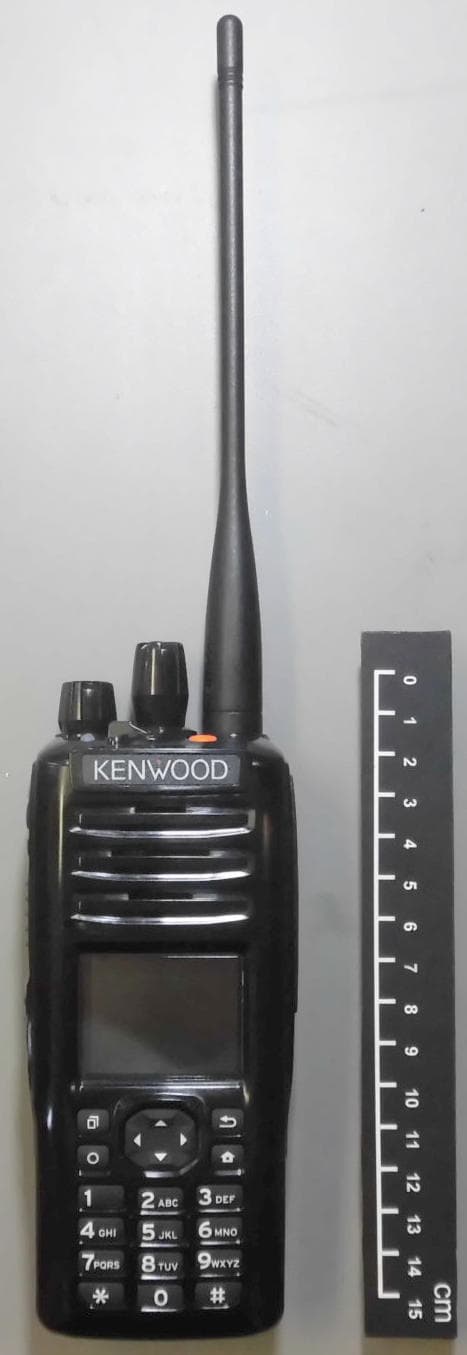
ALH442000
Jul 06, 2014Push to talk radio.
Equipment Class
DXX - Part 15 Low Power Communication Device Transmitter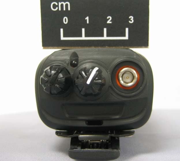
ALH443801
Dec 09, 2013UHF Digital Transceiver
Equipment Class
TNF - Licensed Non-Broadcast Transmitter Held to Face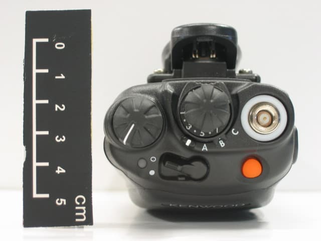
ALH468800
Oct 22, 2013PORTABLE LMR RADIO
Equipment Class
TNF - Licensed Non-Broadcast Transmitter Held to Face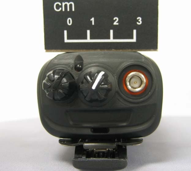
ALH443700
Aug 18, 2013VHF Digital Transceiver Models NX-240-P, NX-240-K, NX-240-M, NX-240-M2, NX-240V-K
Equipment Class
TNF - Licensed Non-Broadcast Transmitter Held to Face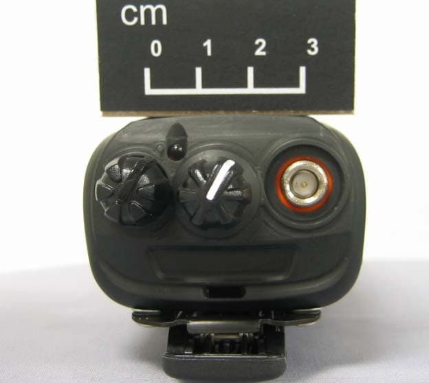
ALH443800
Aug 07, 2013Model NX-340 Digital Transceiver
Equipment Class
TNF - Licensed Non-Broadcast Transmitter Held to Face