ALH36423110UHF FM Transceiver
Kenwood USA Corporation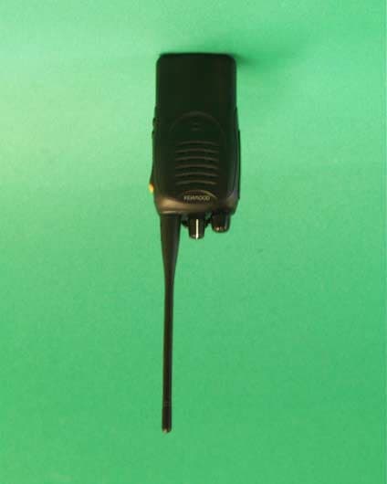
Click to zoom
Application Details
- Equipment Class
- TNF - Licensed Non-Broadcast Transmitter Held to Face
- Date of Grant
- Aug 21, 2003
- Application Purpose
- Original Equipment
- Date of Application
- May 26, 2003
- Equipment Note
- UHF FM Transceiver
- Frequency Range
- 450.00000000 - 490.00000000
- Company
- Kenwood USA Corporation
- Country
- United States
Documents & Files
Document Text
Text extracted from the exhibit documents filed with the FCC. Open a document above to read the original.
Users Manual
KENWOOD CORPORATION FCC ID: ALH36413110/ALH36423110 INSTRUCTION MANUAL TK-2160/TK-3160-1 THANK YOU! We are grateful you chose KENWOOD for your land mobile radio applications. We believe this easy-to-use transceiver will provide dependable communications to keep personnel operating at peak efficiency. KENWOOD transceivers incorporate the latest in advanced technology. As a result, we feel strongly that you will be pleased with the quality and features of this product. NOTICES TO THE USER WARNING: GOVERNMENT LAW PROHIBITS THE OPERATION OF UNLICENSED RADIO TRANSMITTERS WITHIN THE TERRITORIES UNDER GOVERNMENT CONTROL. ILLEGAL OPERATION IS PUNISHABLE BY FINE OR IMPRISONMENT OR BOTH. REFER SERVICE TO QUALIFIED TECHNICIANS ONLY. DO NOT OPERATE YOUR TRANSCEIVER IN EXPLOSIVE ATMOSPHERES (GASES, DUST, FUMES, ETC.). TURN OFF YOUR TRANSCEIVER WHILE TAKING ON FUEL, OR WHILE PARKED IN GASOLINE SERVICE STATIONS. SAFETY: It is important that the operator is aware of and understands hazards common to the operation of any transceiver. WARNING: EXPLOSIVE ATMOSPHERES (GASES, DUST, FUMES, etc.) Turn off your transceiver while taking on fuel, or while parked in gasoline service stations. One or more of the following statements may be applicable: FCC WARNING This equipment generates or uses radio frequency energy. Changes or modifications to this equipment may cause harmful interference unless the modifications are expressly approved in the instruction manual. The user could lose the authority to operate this equipment if an unauthorized change or modification is made. INFORMATION TO THE DIGITAL DEVICE USER REQUIRED BY THE FCC This equipment has been tested and found to comply with the limits for a Class B digital device, pursuant to Part 15 of the FCC Rules. These limits are designed to provide reasonable protection against harmful interference in a residential installation. This equipment generates, uses and can generate radio frequency energy and, if not installed and used in accordance with the instructions, may cause harmful interference to radio communications. However, there is no guarantee that the interference will not occur in a particular installation. If this equipment does cause harmful interference to radio or television reception, which can be determined by turning the equipment off and on, the user is encouraged to try to correct the interference by one or more of the following measures: Reorient or relocate the receiving antenna. Increase the separation between the equipment and receiver. Connect the equipment to an outlet on a circuit different from that to which the receiver is connected. Consult the dealer for technical assistance. KENWOOD CORPORATION FCC ID: ALH36413110/ALH36423110 ATTENTION (U.S.A. Only): The RBRC Recycle seal found on KENWOOD nickel-cadmium (Ni-Cd) battery packs indicates KENWOOD ’s voluntary participation in an industry program to collect and recycle Ni-Cd batteries after their operating life has expired. The RBRC program is an alternative to disposing Ni-Cd batteries with your regular refuse or in municipal waste streams, which is illegal in some areas. For information on Ni-Cd battery recycling in your area, call (toll free) 1-800-8-BATTERY (1-800-822-8837). KENWOOD ’s involvement in this program is part of our commitment to preserve our environment and conserve our natural resources. UNPACKING AND CHECKING EQUIPMENT Note: The following unpacking instructions are for use by your KENWOOD dealer, an authorized KENWOOD service facility, or the factory. Carefully unpack the transceiver. We recommend that you identify the items listed in the following table before discarding the packing material. If any items are missing or have been damaged during shipment, file a claim with the carrier immediately. Accessories Quantity Item Part Number K Instruction Manual B62 -1716 - *0 1 Belt Hook J29 –0701-05 1 Screw N35-3004-45 1 Cap B09 - 0676 - *3 1 Hardware Fixture J21 – 8464 - 04 1 KENWOOD CORPORATION FCC ID: ALH36413110/ALH36423110 Installing/ Removing the Optional Battery Pack PREPARATION The battery pack is not charged at the factory; charge it before use. CAUTION: DO NOT RECHARGE THE BATTERY PACK IF IT IS ALREADY FULLY CHARGED. DOING SO MAY CAUSE THE LIFE OF THE BATTERY PACK TO SHORTEN OR THE BATTERY PACK MAY BE DAMAGED. AFTER RECHARGING THE BATTERY PACK, DISCONNECT IT FROM THE CHARGER. IF THE CHARGER POWER IS RESET (TURNED ON AFTER BEING TURNED OFF), RECHARGING WILL START AGAIN AND THE BATTERY PACK WILL BECOME OVERCHARGED. DO NOT SHORT THE BATTERY TERMINALS OR DISPOSE OF THE BATTERY BY FIRE. NEVER ATTEMPT TO REMOVE THE CASING FROM THE BATTERY PACK. 1 Match the guides of the battery pack with the corresponding grooves on the upper rear of the transceiver, then firmly press the battery pack t 2 Flip the safety catch into place to prevent accidentally pressing the release latch and removing the battery. 3 To remove the battery pack, lift the safety catch, press the release latch,then pull the battery pack away from the transceiver. KENWOOD CORPORATION FCC ID: ALH36413110/ALH36423110 Installing the Antenna Screw the antenna into the connector on the top of the transceiver by holding the antenna at its base and turning it clockwise until secure. Installing the Belt Clip 1 Remove the two screws from the rear of the transceiver, then remove the small, plastic black covering that was held in place. 2 Insert the belt clip mount into the space on the rear of the transceiver. 3 Using the 2 screws, affix the belt clip in place. Note: Do not dispose of the plastic black covering. If you remove the belt clip, replace the covering into the space on the rear of the transceiver. Either this covering or the belt clip must be in place, otherwise the battery pack may not remain installed properly. KENWOOD CORPORATION FCC ID: ALH36413110/ALH36423110 Installing the Cap over the Speaker/Microphone Jacks If you are not using an optional speaker/ microphone, install the cap over the SP/MIC jacks usi…
Text truncated - open the document above for the full version.
Attestation Statements
August 27, 2001 Federal Communications Commission Authorization & Evaluation Division 7435 Oakland Mills Road Columbia, MD 21046 Gentlemen: Reference: This equipment meets the requirements of FCC Rules, Parts 90.203(e) and (g) as applicable. Programming of this product’s transmit frequencies can be performed ONLY by the manufacturer or by service or maintenance personnel. The operator cannot program transmit frequencies using the equipment’s external operation controls. Sincerely, Kenwood Communications Corporation Joel E. Berger Joel. E. Berger Staff Engineer Kenwood Communications Corporation Research & Development Department Corporate Headquarters Kenwood Communications Corporation 3975 Johns Creek Court, Suite 300 Suwanee, GA 30024 678-474-4700 Distribution: 2201 E. Dominguez St. Long Beach, CA 90810 (310) 639-4200 Mailing Address: P.O. Box 22745 Long Beach, CA 90801-5745
Cover Letter(s)
August 27, 2001 Federal Communications Commission Authorization & Evaluation Division 7435 Oakland Mills Road Columbia, MD 21046 Gentlemen: This letter will authorize the appointment of MORTON FLOM, P. Eng. and/or M. Flom Associates, Inc. to act as our agent in all FCC matters. This appointment is effective until you are otherwise notified by us. This is to advise that we are in full compliance with the Anti-Drug Abuse Act. The application is not subject to a denial of federal benefits pursuant to section 5301 of the Anti-Drug Abuse Act of 1988, 21 USC 8.62, and no party to the application is subject to a denial of federal benefits pursuant to that section. Sincerely, Kenwood Communications Corporation Joel E. Berger Joel E. Berger Staff Engineer Research & Development Department Kenwood Communications Corporation Corporate Headquarters Kenwood Communications Corporation 3975 Johns Creek Court, Suite 300 Suwanee, GA 30024 678-474-4700 Distribution: 2201 E. Dominguez St. Long Beach, CA 90810 (310) 639-4200 Mailing Address: P.O. Box 22745 Long Beach, CA 90801-5745
Cover Letter(s)
5/27/2003 Federal Communications Commission EQUIPMENT APPROVAL SERVICES P.O. Box 358315 Pittsburgh, PA 15251-5315 Attention: Authorization and Evaluation Division Reference: FCC ID: ALH36423110 Model TK-3160-1 Dear Sir: Pursuant to Sections 0.457(d)(1)(ii) and 0.459 of the Commission's Rules, the Applicant hereby requests confidential treatment of some of the information accompanying this Application, as listed below: Block Diagram Schematic Diagrams Circuit Description Parts List Active Devices Tuning Procedure These materials contain trade secrets and proprietary information not customarily released to the public. The public disclosure of these matters might be harmful to the Applicant and provide unjustified benefits to its competitors. The Applicant understands that pursuant to Rule 0.457 (d)(1)(ii), disclosure of the Application and all accompanying documentation will not be made before the date of Grant for the Application. Sincerely yours, Morton Flom, P. Eng., President M. Flom Associates, Inc. Agent for Applicant
Cover Letter(s)
August 19, 2003 Applicant: Kenwood Equipment: FCC ID: ALH36423110 EA299622 Reference: Correspondence25585 In response to the above referenced correspondence we present the following: 1) The User cannot program the device. The letter is included in the submittal package as a matter of course. 2) LMR Part 90 does not have a channel plan. 3) Advertised specification is 4W. All Kenwood Communications LMR products use a TX leveling circuit with reserve capacity (headspace); tolerance is typically +/- 0.3 W for a UHF portable. 4) Power and SAR versus time: Please see items uploaded to the RF Exposure Exhibit. 5) SAR for low and high channels: Please see items uploaded to the RF Exposure Exhibit. 6) Justification for verification performed: Please see items uploaded to the RF Exposure Exhibit. We trust the above meets the requirements of the Commission and the Grant will be issued. Regards, M. Flom Associates, Inc.
External Photos
ALH36423110 FCC ID:ALH36423110 Model Name:TK-3160-1 Bottom View
External Photos
ALH36423110 FCC ID:ALH36423110 Model Name:TK-3160-1 Front View
External Photos
ALH36423110 FCC ID:ALH36423110 Model Name:TK-3160-1 Left View
External Photos
ALH36423110 FCC ID:ALH36423110 Model Name:TK-3160-1 Rear View
External Photos
ALH36423110 FCC ID:ALH36423110 Model Name:TK-3160-1 Right View
External Photos
ALH364323110 FCC ID:ALH36423110 Model Name:TK-3160-1 Top View
ID Label/Location Info
Caution LabelFCC ID: ALH36423110 Model Name: TK-3160-1 Caution Label Label Location
ID Label/Location Info
ALH36423110 FCC ID:ALH36423110 Model Name:TK-3160-1 Name Plate
Internal Photos
ALH36423110 FCC ID:ALH36423110 Model Name:TK-3160-1 PC Board Top View
Internal Photos
ALH36423110 FCC ID:ALH36423110 Model Name:TK-3160-1 PC Board Bottom View
RF Exposure Info
Test Report S/N: 042803-372ALH Test Date(s): May 06, 2003 FCC/IC SAR Evaluation © 2003 Celltech Labs Inc. 1 of 21 Celltech Labs Inc. declares under its sole responsibility that this device was found to be in compliance with the Specific Absorption Rate (SAR) RF exposure requirements specified in FCC 47 CFR §2.1093 and Health Canada’s Safety Code 6. The device was tested in accordance with the measurement standards and procedures specified in FCC OET Bulletin 65, Supplement C (Edition 01-01) and Industry Canada RSS-102 Issue 1 (Provisional) for the Occupational / Controlled Exposure environment. I attest to the accuracy of data. All measurements were performed by me or were made under my supervision and are correct to the best of my knowledge and belief. I assume full responsibility for the completeness of these measurements and vouch for the qualifications of all persons taking them. This test report shall not be reproduced partially, or in full, without the prior written approval of Celltech Labs Inc. The results and statements contained in this report pertain only to the device(s) evaluated. Russell W. Pipe Senior Compliance Technologist Celltech Labs Inc. DECLARATION OF COMPLIANCE SAR EVALUATION Test Lab CELLTECH LABS INC. Testing and Engineering Lab 1955 Moss Court Kelowna, B.C. Canada V1Y 9L3 Phone: 250-448-7047 Fax: 250-448-7046 e-mail: [email protected] web site: www.celltechlabs.com Applicant Information KENWOOD USA CORPORATION 3975 John Creek Court, Suite 300 Suwanee, GA 30024 Rule Part(s): FCC 47 CFR §2.1093; IC RSS-102 Issue 1 (Provisional) Test Procedure(s): FCC OET Bulletin 65, Supplement C (Edition 01-01) Device Type: Portable UHF PTT Radio Transceiver FCC ID: ALH46423110 Model(s): TK-3160-1 Modulation: FM (UHF) Tx Frequency Range: 450 - 490 MHz Max. RF Output Power Tested: 4.79 Watts (Conducted) Antenna Type(s): 1. Whip (P/N: KRA-27M) 2. Stubby (P/N: KRA-23M) Battery Type(s): NiMH, 7.2V, 2000mAh (P/N: KNB-26N) Body-Worn Accessories: Belt-Clip, Speaker-Microphone (P/N: KMC-17) Max. SAR Measured: 3.65 W/kg - Face-held (50% Duty Cycle) 4.52 W/kg - Body-worn (50% Duty Cycle) Test Report S/N: 042803-372ALH Test Date(s): May 06, 2003 FCC/IC SAR Evaluation © 2003 Celltech Labs Inc. 2 of 21 TABLE OF CONTENTS 1.0 INTRODUCTION..................................................................... 3 2.0 DESCRIPTION OF EUT............................................................ 3 3.0 SAR MEASUREMENT SYSTEM ............................................... 4 4.0 MEASUREMENT SUMMARY..................................................... 5 5.0 DETAILS OF SAR EVALUATION............................................... 6 6.0 EVALUATION PROCEDURES................................................... 6-7 7.0 SYSTEM PERFORMANCE CHECK............................................. 8 8.0 SIMULATED TISSUE MIXTURES............................................... 9 9.0 SAR LIMITS........................................................................... 9 10.0 SYSTEM SPECIFICATIONS...................................................... 10 11.0 PROBE SPECIFICATION......................................................... 11 12.0 PLANAR PHANTOM................................................................ 11 13.0 VALIDATION PHANTOM........................................................... 11 14.0 DEVICE HOLDER.................................................................... 11 15.0 TEST EQUIPMENT LIST........................................................... 12 16.0 MEASUREMENT UNCERTAINTIES............................................ 13-14 17.0 REFERENCES........................................................................ 15 APPENDIX A - SAR MEASUREMENT DATA............................................... 16 APPENDIX B - SYSTEM PERFORMANCE CHECK DATA............................ 17 APPENDIX C - SYSTEM VALIDATION PROCEDURES................................. 18 APPENDIX D - PROBE CALIBRATION...................................................... 19 APPENDIX E - MEASURED FLUID DIELECTRIC PARAMETERS................... 20 APPENDIX F - SAR TEST SETUP & EUT PHOTOGRAPHS.......................... 21 Test Report S/N: 042803-372ALH Test Date(s): May 06, 2003 FCC/IC SAR Evaluation © 2003 Celltech Labs Inc. Kenwood USA Corporation FCC ID: ALH46423110 3 of 21 Portable UHF PTT Radio Transceiver (450-490MHz) 1.0 INTRODUCTION This measurement report demonstrates compliance of the Kenwood USA Corp. Model: TK-3160-1 Portable UHF PTT Radio Transceiver FCC ID: ALH46423110 with the RF exposure requirements specified in FCC 47 CFR §2.1093 (see reference [1]), and Health Canada’s Safety Code 6 (see reference [2]) for the Occupational / Controlled Exposure environment. The measurement procedures described in FCC OET Bulletin 65, Supplement C (Edition 01-01) (see reference [3]) and IC RSS-102 Issue 1 (Provisional) (see reference [4]), were employed. A description of the product, operating configuration, detailed summary of the test results, methodology and procedures used in the evaluation, equipment used, and the various provisions of the rules are included within this test report. 2.0 DESCRIPTION of Equipment Under Test (EUT) FCC Rule Part(s) 47 CFR §2.1093 IC Rule Part(s) RSS-102 Issue 1 (Provisional) Test Procedure(s) FCC OET Bulletin 65, Supplement C (Edition 01-01) Device Type Portable UHF PTT Radio Transceiver FCC ID ALH46423110 Model(s) TK-3160-1 Serial No. Pre-production unit Modulation FM (UHF) Tx Frequency Range 450 - 490 MHz Max. RF Output Power Tested 4.79 Watts (Conducted) Antenna Type(s) Whip - 152 mm (P/N: KRA-27M) Stubby - 82 mm (P/N: KRA-23M) Battery Type(s) NiMH, 7.2V, 2000mAh (P/N: KNB-26N) Body-Worn Accessories Tested Belt-Clip, Speaker-Microphone (P/N: KMC-17) Test Report S/N: 042803-372ALH Test Date(s): May 06, 2003 FCC/IC SAR Evaluation © 2003 Celltech Labs Inc. Kenwood USA Corporation FCC ID: ALH46423110 4 of 21 Portable UHF PTT Radio Transceiver (450-490MHz) 3.0 SAR MEASUREMENT SYSTEM Celltech Labs…
Text truncated - open the document above for the full version.
RF Exposure Info
Celltech Labs Inc. 1955 Moss Court, Kelowna, B.C. Canada V1Y 9L3 Tel. 250-448-7047 • Fax. 250-448-7046 • e-mail: [email protected] www.celltechlabs.com August 19, 2003 Federal Communications Commission Equipment Approval Services 7435 Oakland Mills Road Columbia, MD 21046 Attn: Stan Lyles SUBJECT: Kenwood Communications Corporation FCC ID: ALH46423110 731 Confirmation No.: EA299622 Correspondence Ref. No.: 25585 Dear Stan: On behalf of Kenwood Communications Corporation is our response to your request for additional information regarding the RF exposure exhibit of the subject application. 1. Attached is the SAR versus time plot as referenced in the SAR report. The power drift was measured using a Gigatronics 8652A power meter before and after each test and does not provide associated measurement plots. 2. Please see attached SAR measurement data and plots for face-held configuration, low and high channels. 3. Please see attached system verification performed with current certified probe conversion factors to confirm system operation during the original SAR evaluation. If you have any further questions regarding the above, please do not hesitate to contact us. Sincerely, Jonathan Hughes General Manager Celltech Labs Inc. cc: Kenwood Communications Corporation M. Flom Associates, Inc.
RF Exposure Info
Kenwood USA Corporation FCC ID: ALH46423110 Small Planar Phantom; Planar Section Probe: ET3DV6 - SN1387; ConvF(7.70,7.70,7.70); Crest factor: 1.0 450 MHz Muscle: σ = 0.91 mho/m ε r = 56.6 ρ = 1.00 g/cm 3 Time Sweep Body-Worn SAR with 0.9 cm Belt-Clip Separation Distance TK-3160-1 Portable UHF PTT Radio Transceiver with Speaker-Microphone Accessory (KMC-17) Stubby Antenna (KRA-23M) NiMH Battery (KNB-26N) Continuous Wave Mode Mid Channel [470.05 MHz] Conducted Power: 4.79 Watts Ambient Temp 23.3 °C; Fluid Temp 23.5 °C Date Tested: May 6, 2003 05/06/03 Celltech Labs Inc. 8.0 9.0 10.0 11.0 12.0 0100200300400500600700800900100011001200 SAR tot [mW/g] [s]
RF Exposure Info
Test Report S/N: 042803-372ALH Test Date(s): August 18, 2003 FCC/IC SAR Evaluation © 2003 Celltech Labs Inc. Kenwood USA Corporation FCC ID: ALH46423110 Portable UHF PTT Radio Transceiver (450-490MHz) MEASUREMENT SUMMARY Note(s): 1. The ambient and fluid temperatures were measured prior to, and during, the fluid dielectric parameter check and the SAR evaluation. The temperatures listed were consistent for all measurement periods. 2. The dielectric properties of the simulated tissue fluid were measured prior to the evaluation using an 85070C Dielectric Probe Kit and an 8753E Network Analyzer (see attached printout of measured fluid dielectric parameters). 3. The EUT was evaluated in a face-held configuration with the front of the radio placed parallel to the outer surface of the planar phantom. A 2.5 cm separation distance was maintained between the front side of the EUT and the outer surface of the planar phantom for the duration of the tests. The EUT was evaluated for face-held SAR with both whip and stubby type antennas. 4. The conducted power levels were measured before and after each test according to the procedures described in FCC 47 CFR §2.1046. The measured conducted power drifts were comparable to those measured during the original SAR evaluation, therefore the original SAR versus time data was used for scaled SAR results as shown in the above table. 5. The EUT was tested in unmodulated continuous transmit operation (Continuous Wave mode at 100% duty cycle) with the transmit key constantly depressed. For a push-to-talk device the 50% duty cycle compensation reported assumes a transmit/receive cycle of equal time base. 6. The EUT was tested with a fully charged battery. 7. Due to the size of the EUT, a Plexiglas planar phantom was used in place of the SAM phantom. 8. A stack of low-density, low-loss dielectric foamed polystyrene was used in place of the device holder. SAR EVALUATION RESULTS Measured Conducted RF Output Power Measured SAR (W/kg) Scaled SAR (W/kg) Freq. (MHz) Chan. Before (W) After (W) Drift (dB) Antenna Type Separ. Dist. (cm) Test Type 100% Duty Cycle 50% Duty Cycle SAR versus Time Drift (dB) 100% Duty Cycle 50% Duty Cycle 450.05 Low 4.83 4.36 -0.45 Whip KRA-27(M) 2.5 Face-held 5.09 2.55 1.34 6.93 3.47 489.95 High 4.85 4.37 -0.46 Whip KRA-27(M) 2.5 Face-held 4.56 2.28 1.34 6.21 3.11 450.05 Low 4.63 4.23 -0.39 Stubby KRA-23(M) 2.5 Face-held 5.52 2.76 1.34 7.52 3.76 489.95 High 4.78 4.29 -0.47 Stubby KRA-23(M) 2.5 Face-held 6.33 3.17 1.34 8.62 4.31 ANSI / IEEE C95.1 1992 - SAFETY LIMIT Spatial Peak - Controlled Exposure / Occupational BRAIN: 8.0 W/kg (averaged over 1 gram) Measured Fluid Type 450MHz Brain Atmospheric Pressure 101.5 kPa IEEE Target Measured Relative Humidity 48 % Dielectric Constant ε r 43.5 (+/-5%) 43.1 Ambient Temperature 24.4 °C IEEE Target Measured Fluid Temperature 21.6 °C Conductivity σ (mho/m) 0.87 (+/-5%) 0.84 Fluid Depth ≥ 15 cm
RF Exposure Info
Kenwood USA Corporation FCC ID: ALH46423110 Small Planar Phantom; Flat Section; Position: (90°,270°) Probe: ET3DV6 - SN1387; ConvF(7.50,7.50,7.50); Crest factor: 1.0 Brain 450 MHz: σ = 0.84 mho/m ε r = 43.1 ρ = 1.00 g/cm 3 Coarse: Dx = 20.0, Dy = 20.0, Dz = 10.0 Cube 5x5x7 SAR (1g): 5.52 mW/g, SAR (10g): 3.93 mW/g Face-Held SAR with 2.5 cm Separation Distance TK-3160-1 Portable UHF PTT Radio Transceiver Whip Antenna (KRA-27M) 7.2 V NiMH Battery (KNB-26N) Continuous Wave Mode Low Channel [450.05 MHz] Conducted Power: 4.83 Watts Ambient Temp 24.4 °C; Fluid Temp 21.6 °C Date Tested: August 18, 2003 SAR Tot [mW/g] 5.76E-1 1.15E+0 1.73E+0 2.30E+0 2.88E+0 3.46E+0 4.03E+0 4.61E+0 5.18E+0 5.76E+0 08/18/03 Celltech Labs Inc. Kenwood USA Corporation FCC ID: ALH46423110 Small Planar Phantom; Flat Section; Position: (90°,270°) Probe: ET3DV6 - SN1387; ConvF(7.50,7.50,7.50); Crest factor: 1.0 Brain 450 MHz: σ = 0.84 mho/m ε r = 43.1 ρ = 1.00 g/cm 3 Coarse: Dx = 20.0, Dy = 20.0, Dz = 10.0 Cube 5x5x7 SAR (1g): 6.33 mW/g, SAR (10g): 4.50 mW/g Face-Held SAR with 2.5 cm Separation Distance TK-3160-1 Portable UHF PTT Radio Transceiver Whip Antenna (KRA-27M) 7.2 V NiMH Battery (KNB-26N) Continuous Wave Mode High Channel [489.95 MHz] Conducted Power: 4.85 Watts Ambient Temp 24.4 °C; Fluid Temp 21.6 °C Date Tested: August 18, 2003 SAR Tot [mW/g] 7.00E-1 1.40E+0 2.10E+0 2.80E+0 3.50E+0 4.20E+0 4.90E+0 5.60E+0 6.30E+0 7.00E+0 08/18/03 Celltech Labs Inc. Kenwood USA Corporation FCC ID: ALH46423110 Small Planar Phantom Probe: ET3DV6 - SN1387; ConvF(7.50,7.50,7.50); Crest factor: 1.0 Brain 450 MHz: σ = 0.84 mho/m ε r = 43.1 ρ = 1.00 g/cm 3 Z-Axis Extrapolation at Peak SAR Location Face-Held SAR with 2.5 cm Separation Distance TK-3160-1 Portable UHF PTT Radio Transceiver Whip Antenna (KRA-27M) 7.2 V NiMH Battery (KNB-26N) Continuous Wave Mode High Channel [489.95 MHz] Conducted Power: 4.85 Watts Ambient Temp 24.4 °C; Fluid Temp 21.6 °C Date Tested: August 18, 2003 08/18/03 Celltech Labs Inc. 0 2 4 6 8 10 0102030405060708090100110120130140150 SAR tot [mW/g] [mm] Kenwood USA Corporation FCC ID: ALH46423110 Small Planar Phantom; Flat Section; Position: (90°,270°) Probe: ET3DV6 - SN1387; ConvF(7.50,7.50,7.50); Crest factor: 1.0 Brain 450 MHz: σ = 0.84 mho/m ε r = 43.1 ρ = 1.00 g/cm 3 Coarse: Dx = 20.0, Dy = 20.0, Dz = 10.0 Cube 5x5x7 SAR (1g): 5.09 mW/g, SAR (10g): 3.62 mW/g Face-Held SAR with 2.5 cm Separation Distance TK-3160-1 Portable UHF PTT Radio Transceiver Stubby Antenna (KRA-23M) 7.2 V NiMH Battery (KNB-26N) Continuous Wave Mode Low Channel [450.05 MHz] Conducted Power: 4.63 Watts Ambient Temp 24.4 °C; Fluid Temp 21.6 °C Date Tested: August 18, 2003 SAR Tot [mW/g] 5.07E-1 1.01E+0 1.52E+0 2.03E+0 2.54E+0 3.04E+0 3.55E+0 4.06E+0 4.56E+0 5.07E+0 08/18/03 Celltech Labs Inc. Kenwood USA Corporation FCC ID: ALH46423110 Small Planar Phantom; Flat Section; Position: (90°,270°) Probe: ET3DV6 - SN1387; ConvF(7.50,7.50,7.50); Crest factor: 1.0 Brain 450 MHz: σ = 0.84 mho/m ε r = 43.1 ρ = 1.00 g/cm 3 Coarse: Dx = 20.0, Dy = 20.0, Dz = 10.0 Cube 5x5x7 SAR (1g): 4.56 mW/g, SAR (10g): 3.24 mW/g Face-Held SAR with 2.5 cm Separation Distance TK-3160-1 Portable UHF PTT Radio Transceiver Stubby Antenna (KRA-23M) 7.2 V NiMH Battery (KNB-26N) Continuous Wave Mode High Channel [489.95 MHz] Conducted Power: 4.78 Watts Ambient Temp 24.4 °C; Fluid Temp 21.6 °C Date Tested: August 18, 2003 SAR Tot [mW/g] 4.92E-1 9.83E-1 1.48E+0 1.97E+0 2.46E+0 2.95E+0 3.44E+0 3.93E+0 4.43E+0 4.92E+0 08/18/03 Celltech Labs Inc.
RF Exposure Info
Test Report S/N: 042803-372ALH Test Date(s): August 18, 2003 FCC/IC SAR Evaluation © 2003 Celltech Labs Inc. Kenwood USA Corporation FCC ID: ALH46423110 Portable UHF PTT Radio Transceiver (450-490MHz) SYSTEM PERFORMANCE CHECK Prior to the SAR evaluation a system check was performed using a planar phantom with a 450MHz dipole (see attached system validation procedure). The dielectric parameters of the simulated tissue fluids were measured prior to the system check using an 85070C Dielectric Probe Kit and an 8753E Network Analyzer (see Appendix E for printout of measured fluid dielectric parameters). A forward power of 250mW was applied to the dipole and the system was verified to a tolerance of + 10% (see Appendix B for system check test plot). PM1 Att1 x Dipole 3D Probe positioner Flat Phantom Field probe Signal Generator AmpLow Pass 3dB Att3 Dir.Coupler Att2 PM2 Cable PM3 d System Check Setup Diagram 450MHz System Check Setup SYSTEM PERFORMANCE CHECK SAR 1g (W/kg) Dielectric Constant ε r Conductivity σ (mho/m) Test Date 450MHz Equiv. Tissue IEEE Target Measured IEEE Target Measured IEEE Target Measured ρ (Kg/m 3 ) Ambient Temp. Fluid Temp. Fluid Depth 08/18/03 Brain 1.23 (±10%) 1.24 43.5 (±5%) 43.1 0.87 (±5%) 0.84 1000 24.4 °C 21.6 °C ≥ 15 cm Note(s): 1. The ambient and fluid temperatures were measured prior to, and during, the fluid dielectric parameter check and the system performance check. The temperatures listed in the table above were consistent for all measurement periods.
RF Exposure Info
System Performance Check - 450MHz Dipole Large Planar Phantom; Planar Section Probe: ET3DV6 - SN1387; ConvF(7.50,7.50,7.50); Crest factor: 1.0; Brain 450 MHz: σ = 0.84 mho/m ε r = 43.1 ρ = 1.00 g/cm 3 Cube 5x5x7: Peak: 2.03 mW/g, SAR (1g): 1.25 mW/g, SAR (10g): 0.808 mW/g, (Worst-case extrapolation) Penetration depth: 11.9 (10.1, 14.3) [mm] Powerdrift: 0.02 dB 450MHz System Validation Forward Conducted Power: 250 mW Ambient Temp 24.4 °C; Fluid Temp 21.6 °C Date Tested: August 18, 2003 SAR Tot [mW/g] 1.20E-1 2.41E-1 3.61E-1 4.82E-1 6.02E-1 7.22E-1 8.43E-1 9.63E-1 1.08E+0 1.20E+0 08/18/03 Celltech Labs Inc.
RF Exposure Info
Celltech Labs Inc. 1955 Moss Court, Kelowna, B.C. Canada V1Y 9L3 Tel. 250-448-7047• Fax. 250-448-7046• e-mail: [email protected] www.celltechlabs.com 450MHz SYSTEM VALIDATION DIPOLE Type: Serial Number: Place of Calibration: Date of Calibration: Celltech Labs Inc. hereby certifies that this device has been calibrated on the date indicated above. Calibrated by: Approved by: 450MHz Validation Dipole 136 Celltech Labs Inc. August 18, 2003 1. Dipole Construction & Electrical Characteristics The validation dipole was constructed in accordance with the IEEE Std “Recommended Practice for Determining the Spatial-Peak Specific Absorption Rate (SAR) in the Human Body Due to Wireless Communications Devices: Experimental Techniques”. The electrical properties were measured using an HP 8753E Network Analyzer. The network analyzer was calibrated to the validation dipole N-type connector feed point using an HP85032E Type N calibration kit. The dipole was placed parallel to a planar phantom at a separation distance of 15.0mm from the simulating fluid using a loss-less dielectric spacer. The measured input impedance is: Feed point impedance at 450MHzRe{Z} = 50.299Ω Im{Z} = 1.6660Ω Return Loss at 450MHz-35.306dB Validation Dipole Dimensions Frequency (MHz)L (mm)h (mm)d (mm) 300420.0250.06.2 450288.0167.06.2 835161.0 89.83.6 900149.0 83.33.6 1450 89.1 51.73.6 1800 72.0 41.73.6 1900 68.0 39.53.6 2000 64.5 37.53.6 245051.8 30.63.6 300041.5 25.03.6 2. Validation Phantom The validation phantom was constructed using relatively low-loss tangent Plexiglas material. The dimensions of the phantom are as follows: Length:83.5 cm Width:36.9 cm Height:21.8 cm The bottom of the phantom is constructed of 6.2 ± 0.1mm Plexiglas. Dimensions of Plexiglas Planar Phantom 2.3 cm 83.5 cm 36.9 cm 99.7 cm 50 cm 19.5 cm 86 cm 0.5 cm 0.62 cm 39.3 cm 21.8 cm 450MHz System Validation Setup 450MHz System Validation Setup 3. Measurement Conditions The planar phantom was filled with brain simulating tissue having the following electrical parameters at 450MHz: Relative Permittivity: 43.1 Conductivity:0.84 mho/m Ambient Temperature: 24.4°C Fluid Temperature:21.6°C Fluid Depth:≥ 15.0 cm The 450MHz simulating tissue consists of the following ingredients: IngredientPercentage by weight Water38.56% Sugar56.32% Salt3.95% HEC0.98% Dowicil 750.19% Target Dielectric Parameters at 22 °C ε r = 43.5 σ = 0.87 S/m 4. SAR Measurement The SAR measurement was performed with the E-field probe in mechanical detection mode only. The setup and determination of the forward power into the dipole was performed using the following procedures. PM1 Att1 x Dipole 3D Probe positioner Flat Phantom Field probe Signal Generator AmpLow Pass 3dB Att3 Dir.Coupler Att2 PM2 Cable PM3 d First the power meter PM1 (including attenuator Att1) is connected to the cable to measure the forward power at the location of the dip…
Text truncated - open the document above for the full version.
Contact Information
Applicant
Angelina Seay(Regulatory Support Engineer)
Technical Contact
M. Flom Associates, Inc.Morton Flom
[email protected]480-926-3100
3356 N. San Marcos Pl., Suite 107 · Chandler, Arizona · United States
Non-Technical Contact
M. Flom Associates, Inc.Morton Flom
[email protected]480-926-3100
Test Firm
M. Flom Associates, Inc.Morton Flom
Technical Specifications
| # | Rule Parts | Frequency Range | Power Output | Emission | Tolerance |
|---|---|---|---|---|---|
| 4 | 9 | 450 MHz - 490 MHz | 4 W | 16K0F3E | 2.5 ppm |
Other Applications from Kenwood USA Corporation
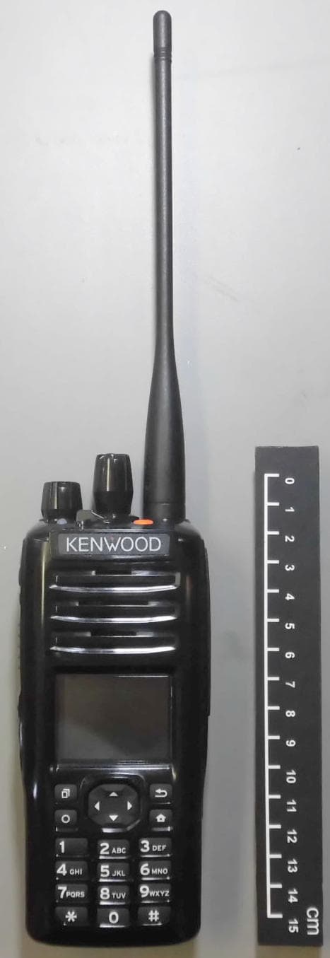
ALH442000
Jul 06, 2014Push to talk radio.
Equipment Class
DXX - Part 15 Low Power Communication Device Transmitter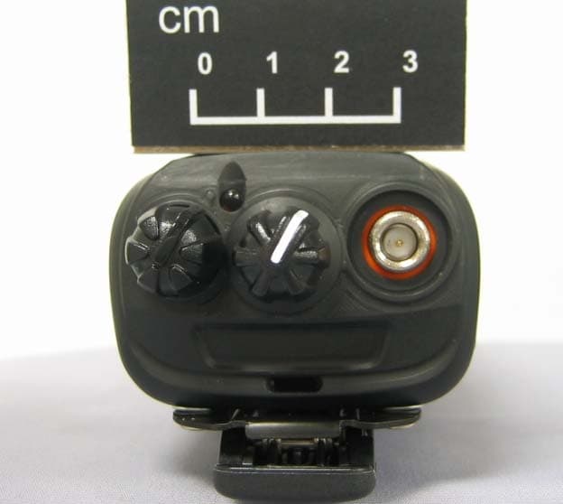
ALH443801
Dec 09, 2013UHF Digital Transceiver
Equipment Class
TNF - Licensed Non-Broadcast Transmitter Held to Face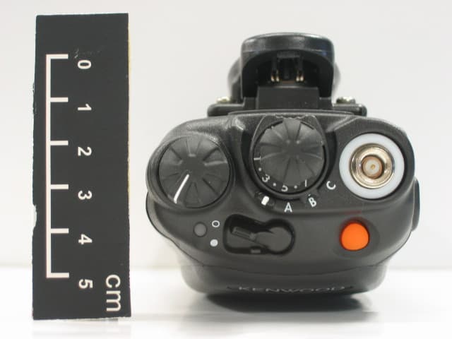
ALH468800
Oct 22, 2013PORTABLE LMR RADIO
Equipment Class
TNF - Licensed Non-Broadcast Transmitter Held to Face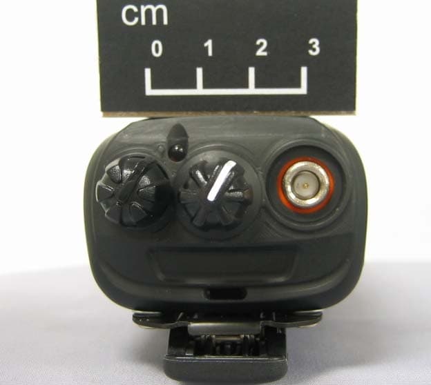
ALH443700
Aug 18, 2013VHF Digital Transceiver Models NX-240-P, NX-240-K, NX-240-M, NX-240-M2, NX-240V-K
Equipment Class
TNF - Licensed Non-Broadcast Transmitter Held to Face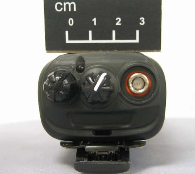
ALH443800
Aug 07, 2013Model NX-340 Digital Transceiver
Equipment Class
TNF - Licensed Non-Broadcast Transmitter Held to Face