ALH36423120UHF/FM HANDHELD TRANSCEIVER
Kenwood USA Corporation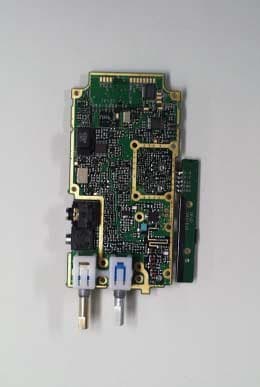
Click to zoom
Application Details
- Equipment Class
- TNF - Licensed Non-Broadcast Transmitter Held to Face
- Date of Grant
- Oct 26, 2003
- Application Purpose
- Original Equipment
- Date of Application
- Oct 26, 2003
- Equipment Note
- UHF/FM HANDHELD TRANSCEIVER
- Frequency Range
- 470.00000000 - 511.98750000
- Company
- Kenwood USA Corporation
- Country
- United States
Documents & Files
Document Text
Text extracted from the exhibit documents filed with the FCC. Open a document above to read the original.
Users Manual
KENWOOD CORPORATIONFCC ID: ALH36423120 FCC ID: ALH36423130 IC: 282D-36423130 INSTRUCTION MANUAL TK-3160-2,-3 THANK YOU! We are grateful you chose KENWOOD for your land mobile radio applications. We believe this easy-to-use transceiver will provide dependable communications to keep personnel operating at peak efficiency. KENWOOD transceivers incorporate the latest in advanced technology. As a result, we feel strongly that you will be pleased with the quality and features of this product. NOTICES TO THE USER WARNING: ** GOVERNMENT LAW PROHIBITS THE OPERATION OF UNLICENSED RADIO TRANSMITTERS WITHIN THE TERRITORIES UNDER GOVERNMENT CONTROL. ** ILLEGAL OPERATION IS PUNISHABLE BY FINE OR IMPRISONMENT OR BOTH. ** REFER SERVICE TO QUALIFIED TECHNICIANS ONLY. ** DO NOT OPERATE YOUR TRANSCEIVER IN EXPLOSIVE ATMOSPHERES (GASES, DUST, FUMES, ETC.). ** TURN OFF YOUR TRANSCEIVER WHILE TAKING ON FUEL, OR WHILE PARKED IN GASOLINE SERVICE STATIONS. SAFETY: It is important that the operator is aware of and understands hazards common to the operation of any transceiver. WARNING: EXPLOSIVE ATMOSPHERES (GASES, DUST, FUMES, etc.) Turn off your transceiver while taking on fuel, or while parked in gasoline service stations. One or more of the following statements may be applicable: FCC WARNING This equipment generates or uses radio frequency energy. Changes or modifications to this equipment may cause harmful interference unless the modifications are expressly approved in the instruction manual. The user could lose the authority to operate this equipment if an unauthorized change or modification is made. INFORMATION TO THE DIGITAL DEVICE USER REQUIRED BY THE FCC This equipment has been tested and found to comply with the limits for a Class B digital device, pursuant to Part 15 of the FCC Rules. These limits are designed to provide reasonable protection against harmful interference in a residential installation. This equipment generates, uses and can generate radio frequency energy and, if not installed and used in accordance with the instructions, may cause harmful interference to radio communications. However, there is no guarantee that the interference will not occur in a particular installation. If this equipment does cause harmful interference to radio or television reception, which can be determined by turning the equipment off and on, the user is encouraged to try to correct the interference by one or more of the following measures: • Reorient or relocate the receiving antenna. • Increase the separation between the equipment and receiver. • Connect the equipment to an outlet on a circuit different from that to which the receiver is connected. • Consult the dealer for technical assistance. KENWOOD CORPORATIONFCC ID: ALH36423120 FCC ID: ALH36423130 IC: 282D-36423130 ATTENTION (U.S.A. Only): The RBRC Recycle seal found on KENWOOD nickel-cadmium (Ni-Cd) battery packs indicates KENWOOD’s voluntary participation in an industry program to collect and recycle Ni-Cd batteries after their operating life has expired. The RBRC program is an alternative to disposing Ni-Cd batteries with your regular refuse or in municipal waste streams, which is illegal in some areas. For information on Ni-Cd battery recycling in your area, call (toll free) 1-800-8- BATTERY (1-800-822-8837). KENWOOD’s involvement in this program is part of our commitment to preserve our environment and conserve our natural resources. UNPACKING AND CHECKING EQUIPMENT Note: The following unpacking instructions are for use by your KENWOOD dealer, an authorized KENWOOD service facility, or the factory. Carefully unpack the transceiver. We recommend that you identify the items listed in the following table before discarding the packing material. If any items are missing or have been damaged during shipment, file a claim with the carrier immediately. ** Accessories Quantity Item Part Number K Instruction Manual B62 -1716 - *01 Belt Hook J29 -0701-05 1 Screw N35-3004-451 Cap B09 - 0676 - *31 Hardware Fixture J21 - 8464 - 041 KENWOOD CORPORATIONFCC ID: ALH36423120 FCC ID: ALH36423130 IC: 282D-36423130 Installing/ Removing the Optional Battery Pack PREPARATION The battery pack is not charged at the factory; charge it before use. CAUTION: ** DO NOT RECHARGE THE BATTERY PACK IF IT IS ALREADY FULLY CHARGED. DOING SO MAY CAUSE THE LIFE OF THE BATTERY PACK TO SHORTEN OR THE BATTERY PACK MAY BE DAMAGED. ** AFTER RECHARGING THE BATTERY PACK, DISCONNECT IT FROM THE CHARGER. IF THE CHARGER POWER IS RESET (TURNED ON AFTER BEING TURNED OFF), RECHARGING WILL START AGAIN AND THE BATTERY PACK WILL BECOME OVERCHARGED. ** DO NOT SHORT THE BATTERY TERMINALS OR DISPOSE OF THE BATTERY BY FIRE. ** NEVER ATTEMPT TO REMOVE THE CASING FROM THE BATTERY PACK. 1 Match the guides of the battery pack with the corresponding grooves on the upper rear of the transceiver, then firmly press the battery pack t 2 Flip the safety catch into place to prevent accidentally pressing the release latch and removing the battery. 3 To remove the battery pack, lift the safety catch, press the release latch,then pull the battery pack away from the transceiver. KENWOOD CORPORATIONFCC ID: ALH36423120 FCC ID: ALH36423130 IC: 282D-36423130 Installing the Antenna Screw the antenna into the connector on the top of the transceiver by holding the antenna at its base and turning it clockwise until secure. Installing the Belt Clip 1 Remove the two screws from the rear of the transceiver, then remove the small, plastic black covering that was held in place. 2 Insert the belt clip mount into the space on the rear of the transceiver. 3 Using the 2 screws, affix the belt clip in place. Note: Do not dispose of the plastic black covering. If you remove the belt clip, replace the covering into the space on the rear of the transceiver. Either this covering or the belt clip must be in place, otherwise the battery pack may not remain installed properly. KENWOOD CORPORATIONFCC ID: ALH36423120 FCC ID: ALH36423130 IC: 282D-3642…
Text truncated - open the document above for the full version.
Users Manual
RADIO FREQUENCY ENERGY SAFETY INFORMATION _____ This KENWOOD transceiver has been tested and complies with the standards listed below, in regards to Radio Frequency (RF) energy and electromagnetic energy (EME) generated by the transceiver. • FCC RF exposure limits for Occupational Use Only. RF Exposure limits adopted by the FCC are generally based on recommendations from the National Council on Radiation Protection and Measurements, & the American National Standards Institute. • FCC OET Bulletin 65 Edition 97-01 Supplement C • American National Standards Institute (C95.1 – 1992) • American National Standards Institute (C95.3 – 1992) WARNING This KENWOOD transceiver generates RF EME while transmitting. RF EME (Radio Frequency Electric & Magnetic Energy) has the potential to cause slight thermal, or heating effects to any part of your body less than the recommended distance from this radio transmitter’s antenna. RF energy exposure is determined primarily by the distance to and the power of the transmitting device. In general, RF exposure is minimized when the lowest possible power is used or transmission time is kept to the minimum required for consistent communications, and the greatest distance possible from the antenna to the body is maintain. The transceiver has been designed for and is classified for Occupational Use Only. Occupational/ controlled exposure limits are applicable to situations in which persons are exposed to RF energy as a consequence of their employment, and such persons have been made aware of the potential for exposure and can exercise control over their exposure. This means you can use the transceiver only if you are aware of the hazards of operating a transceiver and are familiar in ways to minimize these hazards. This transceiver is not intended for use by the general public in uncontrolled environments. Uncontrolled environment exposure limits are applicable to situations in which the general public may be exposed to RF energy, or in which the persons who are exposed as a consequence of their employment may not be fully aware of the potential for exposure or cannot exercise control over their exposure. The following list provides you with the information required to ensure that you are aware of RF exposure and of how to operate this transceiver so that the FCC RF exposure limitations are not exceeded. • While transmitting (holding the PTT switch), always keep the antenna at least 3 cm (1 3/16 inches) from your body or face, as well as from any bystanders. • Do not transmit for more than 50% of the total transceiver use time; transmitting over 50% of the total use time may exceed the limits in accordance to the FCC RF exposure requirements. Nominal transceiver operation is 5% transmission time, 5% reception time, and 90% stand-by time. • Use only the specified antenna for this transceiver; this may be either the antenna provided with the transceiver or another antenna authorized by KENWOOD. Use only KENWOOD authorized accessories (antennas, battery packs, belt clips, Speaker/ Mics or headsets etc.): When worn on the body, always place the radio in a KENWOOD recommended clip or carrying case meant for this product. The use of other than recommended or approved body- worn accessories may result in RF exposure levels which exceed the FCC’s occupational/ controlled environment RF exposure limits. CAUTION To ensure that your exposure to RF EME is within the FCC limits for occupational use, you must observe and adhere to the above points. Electromagnetic Interference Compatibility Electronic devices are susceptible to electromagnetic interference (EMI) if they are not adequately shielded or designed for electromagnetic compatibility. Because this transceiver generates RF energy, it can cause interference to such equipment. • Turn OFF your transceiver where signs are posted to do so. Hospitals and health care facilities use equipment that is sensitive to electromagnetic radiation. • Turn OFF your transceiver while on board an aircraft when so instructed. Use of the transceiver must be in accordance with airline regulations and/or crew instructions.
Attestation Statements
October 22, 2003 Federal Communications Commission Authorization & Evaluation Division 7435 Oakland Mills Road Columbia, MD 21046 Gentlemen: Reference: This equipment meets the requirements of FCC Rules, Parts 90.203(e) and (g) as applicable. Programming of this product’s transmit frequencies can be performed ONLY by the manufacturer or by service or maintenance personnel. The operator cannot program transmit frequencies using the equipment’s external operation controls. Sincerely, Kenwood Communications Corporation Joel E. Berger Joel. E. Berger Staff Engineer Kenwood Communications Corporation Research & Development Department
Cover Letter(s)
10/22/2003 Federal Communications Commission EQUIPMENT APPROVAL SERVICES P.O. Box 358315 Pittsburgh, PA 15251-5315 Attention: Authorization and Evaluation Division Reference: FCC ID: ALH36423120 Model TK-3160-2 Dear Sir: Pursuant to Sections 0.457(d)(1)(ii) and 0.459 of the Commission's Rules, the Applicant hereby requests confidential treatment of some of the information accompanying this Application, as listed below: Block Diagram Schematic Diagrams Circuit Description Parts List Active Devices Tuning Procedure These materials contain trade secrets and proprietary information not customarily released to the public. The public disclosure of these matters might be harmful to the Applicant and provide unjustified benefits to its competitors. The Applicant understands that pursuant to Rule 0.457 (d)(1)(ii), disclosure of the Application and all accompanying documentation will not be made before the date of Grant for the Application. Sincerely yours, Morton Flom, P. Eng.
External Photos
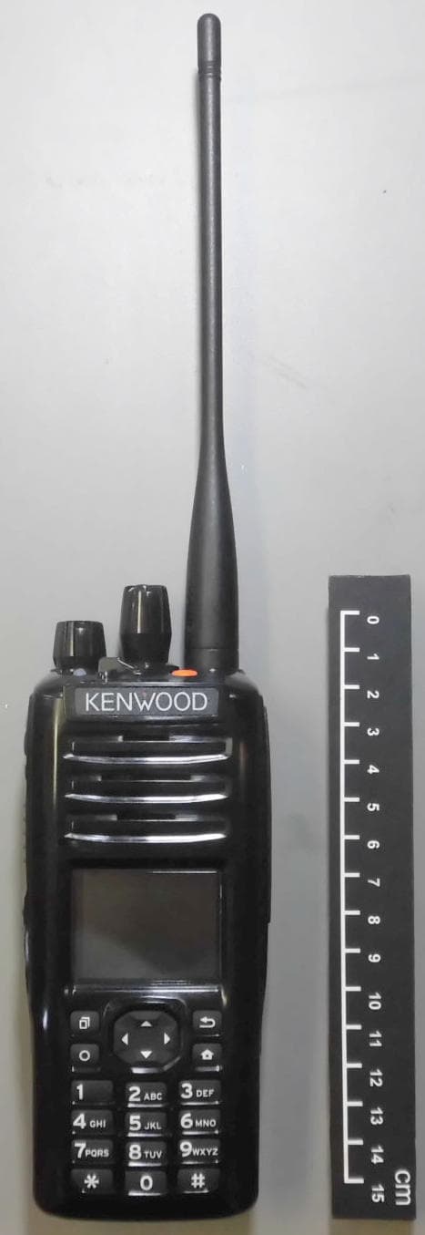
TK-3160-2 FCC ID:ALH36423120 TK-3160-3 FCC ID:ALH36423130 TK-3160-3 IC: 282D-36423130 Front View Front View Front View Front View Rear View Rear View Rear View Rear View TK-3160-2 FCC ID:ALH36423120 TK-3160-3 FCC ID:ALH36423130 TK-3160-3 IC: 282D-36423130 To p Vi ew To p Vi ew To p Vi ew To p Vi ew Bottom View Bottom View Bottom View Bottom View TK-3160-2 FCC ID:ALH36423120 TK-3160-3 FCC ID:ALH36423130 TK-3160-3 IC: 282D-36423130 Left View Left View Left View Left View Right View Right View Right View Right View
ID Label/Location Info
FCC ID:ALH36423120
Internal Photos
TK-3160-2 FCC ID:ALH36423120TK-3160-3 FCC ID:ALH36423130TK-3160-3 IC: 282D-36423130 To p Vi ew To p Vi ew To p Vi ew To p Vi ew Bottom View Bottom View Bottom View Bottom View
RF Exposure Info
© 2003 Celltech Labs Inc. 1 of 20 Test Report S/N: 092903-429ALH Test Date(s): September 30, October 1 & 14 2003 Test Type: FCC SAR Evaluation Celltech Labs Inc. declares under its sole responsibility that this device was found to be in compliance with the Specific Absorption Rate (SAR) RF exposure requirements specified in FCC 47 CFR §2.1093 and Health Canada’s Safety Code 6. The device was tested in accordance with the measurement standards and procedures specified in FCC OET Bulletin 65, Supplement C (Edition 01-01) and Industry Canada RSS-102 Issue 1 (Provisional) for the Occupational / Controlled Exposure environment. I attest to the accuracy of data. All measurements were performed by me or were made under my supervision and are correct to the best of my knowledge and belief. I assume full responsibility for the completeness of these measurements and vouch for the qualifications of all persons taking them. This test report shall not be reproduced partially, or in full, without the prior written approval of Celltech Labs Inc. The results and statements contained in this report pertain only to the device(s) evaluated. Russell W. Pipe Senior Compliance Technologist Celltech Labs Inc. DECLARATION OF COMPLIANCE SAR EVALUATION Test Lab CELLTECH LABS INC. Testing and Engineering Lab 1955 Moss Court Kelowna, B.C. Canada V1Y 9L3 Phone: 250-448-7047 Fax: 250-448-7046 e-mail: [email protected] web site: www.celltechlabs.com Applicant Information KENWOOD USA CORPORATION 3975 John Creek Court, Suite 300 Suwanee, GA 30024 Rule Part(s): FCC 47 CFR §2.1093; IC RSS-102 Issue 1 (Provisional) Test Procedure(s): FCC OET Bulletin 65, Supplement C (Edition 01-01) Device Type: Portable UHF PTT Radio Transceiver FCC ID: ALH36423120 Model(s): TK-3160-2 Modulation: FM (UHF) Tx Frequency Range: 470-512 MHz Max. RF Output Power Tested: 4.28 Watts (Conducted) Antenna Type(s): 1. Whip (P/N: KRA-27 (M2)) 2. Stubby (P/N: KRA-23 (M2)) Battery Type(s): NiMH, 7.2V, 2000mAh (P/N: KNB-26N) Body-Worn Accessories: Belt-Clip, Speaker-Microphone (P/N: KMC-17) Max. SAR Measured: 3.51 W/kg - Face-held (50% Duty Cycle) 6.43 W/kg - Body-worn (50% Duty Cycle) © 2003 Celltech Labs Inc. 2 of 20 Test Report S/N: 092903-429ALH Test Date(s): September 30, October 1 & 14 2003 Test Type: FCC SAR Evaluation TABLE OF CONTENTS 1.0 INTRODUCTION..................................................................... 3 2.0 DESCRIPTION OF EUT............................................................ 3 3.0 SAR MEASUREMENT SYSTEM ............................................... 4 4.0 MEASUREMENT SUMMARY..................................................... 5 5.0 DETAILS OF SAR EVALUATION............................................... 6 6.0 EVALUATION PROCEDURES................................................... 6 7.0 SYSTEM PERFORMANCE CHECK............................................. 7 8.0 SIMULATED TISSUE MIXTURES............................................... 8 9.0 SAR LIMITS........................................................................... 8 10.0 SYSTEM SPECIFICATIONS...................................................... 9 11.0 PROBE SPECIFICATION......................................................... 10 12.0 PLANAR PHANTOM................................................................ 10 13.0 VALIDATION PHANTOM........................................................... 10 14.0 DEVICE HOLDER.................................................................... 10 15.0 TEST EQUIPMENT LIST........................................................... 11 16.0 MEASUREMENT UNCERTAINTIES............................................ 12-13 17.0 REFERENCES........................................................................ 14 APPENDIX A - SAR MEASUREMENT DATA............................................... 15 APPENDIX B - SYSTEM PERFORMANCE CHECK DATA............................ 16 APPENDIX C - SYSTEM VALIDATION PROCEDURES................................. 17 APPENDIX D - PROBE CALIBRATION...................................................... 18 APPENDIX E - MEASURED FLUID DIELECTRIC PARAMETERS................... 19 APPENDIX F - SAR TEST SETUP & EUT PHOTOGRAPHS.......................... 20 © 2003 Celltech Labs Inc. Kenwood USA Corporation FCC ID: ALH36423120 3 of 20 Portable UHF PTT Radio Transceiver (470-512MHz) Test Report S/N: 092903-429ALH Test Date(s): September 30, October 1 & 14 2003 Test Type: FCC SAR Evaluation This measurement report demonstrates compliance of the Kenwood USA Corp. Model: TK-3160-2 Portable UHF PTT Radio Transceiver FCC ID: ALH36423120 with the RF exposure requirements specified in FCC 47 CFR §2.1093 (see reference [1]), and Health Canada’s Safety Code 6 (see reference [2]) for the Occupational / Controlled Exposure environment. The measurement procedures described in FCC OET Bulletin 65, Supplement C (Edition 01-01) (see reference [3]) and IC RSS-102 Issue 1 (Provisional) (see reference [4]), were employed. A description of the product, operating configuration, detailed summary of the test results, methodology and procedures used in the evaluation, equipment used, and the various provisions of the rules are included within this test report. FCC Rule Part(s) 47 CFR §2.1093 IC Rule Part(s) RSS-102 Issue 1 (Provisional) Test Procedure(s) FCC OET Bulletin 65, Supplement C (Edition 01-01) Device Type Portable UHF PTT Radio Transceiver FCC ID ALH36423120 Model(s) TK-3160-2 Serial No. Pre-production unit Modulation FM (UHF) Tx Frequency Range 470-512 MHz Max. RF Output Power Tested 4.28 Watts (Conducted) Antenna Type(s) Whip - 140 mm (P/N: KRA-27(M2)) Stubby - 82 mm (P/N: KRA-23M2) Battery Type(s) NiMH, 7.2V, 2000mAh (P/N: KNB-26N) Body-Worn Accessories Tested Belt-Clip, Speaker-Microphone (P/N: KMC-17) 1.0 INTRODUCTION 2.0 DESCRIPTION OF EQUIPMENT UNDER TEST (EUT) © 2003 Celltech Labs Inc. Kenwood USA Corporation FCC ID: ALH36423120 4 of 20 Portable UHF PTT Radio Transceiver (470-512MHz) Test Report S/N: 092903-429A…
Text truncated - open the document above for the full version.
RF Exposure Info
Celltech Labs Inc. 1955 Moss Court, Kelowna, B.C. Canada V1Y 9L3 Tel. 250-448-7047 x Fax. 250-448-7046 x e-mail: [email protected] www.celltechlabs.com March 26, 2004 Federal Communications Commission Equipment Approval Services 7435 Oakland Mills Road Columbia, MD 21046 Attn: Diane Poole SUBJECT:Kenwood USA Corporation FCC ID: ALH36423120 731 Confirmation No.: TC980512 Correspondence Ref. No.: 10553 Dear Diane: On behalf of Kenwood USA Corporation is our response to your e-mail dated January 6, 2004 requesting additional information for the subject application. 1. Attached is remeasured SAR test data and SAR versus Time plots using a 5x5x7 zoom grid for the worst-case antenna measurement configurations previously reported. The original SAR measurements were performed using a 7x7x7 zoom grid. The 5x5x7 zoom grid provides a shortened zoom scan reporting a more conservative SAR value. The radio was re-evaluated with a fully charged NiMH battery (7.2V, 2000mAh) for both the area scan and zoom scan measurements. Upon completion of the area scan the radio was cooled down to ambient temperature prior to performing the zoom scan. If you have any further questions regarding the above, please do not hesitate to contact us. Sincerely, Jonathan Hughes General Manager Celltech Labs Inc. cc: Kenwood USA Corporation M. Flom Associates, Inc. Stubby Antenna (P/N: KRA-23 (M2)) - 5x5x7 Zoom Scan - March 25, 2004 DUT: Kenwood USA Corp. Model: TK-3160-2; Type: Portable UHF PTT Radio Transceiver; Serial: U2-03 Ambient Temp: 25.0qC; Fluid Temp: 22.4qC; Barometric Pressure: 100.7 kPa; Humidity: 31% Body-worn Accessories: Belt-Clip, Speaker-Microphone Communication System: UHF NiMH Battery (7.2V, 2000mAh) Frequency: 470 MHz; Duty Cycle: 1:1 RF Output Power: 4.05 Watts (Conducted) Medium: M450 (ı = 0.92 mho/m; İ r = 56.8; ȡ = 1000 kg/m 3 - Probe: ET3DV6 - SN1590; ConvF(8.1, 8.1, 8.1); Calibrated: 15/05/2003 - Sensor-Surface: 4mm (Mechanical Surface Detection) - Electronics: DAE3 Sn353; Calibrated: 19/12/2003 - Phantom: Small Planar; Type: Plexiglas; Serial: 161 - Measurement SW: DASY4, V4.2 Build 37; Postprocessing SW: SEMCAD, V1.8 Build 109 Body SAR - 0.9 cm Belt-Clip Separation Distance to Planar Phantom - Low Channel/Area Scan (7x15x1): Measurement grid: dx=15mm, dy=15mm Reference Value = 92.4 V/m Body SAR - 0.9 cm Belt-Clip Separation Distance to Planar Phantom - Low Channel/Zoom Scan (5x5x7)/Cube 0: Measurement grid: dx=8mm, dy=8mm, dz=5mm Peak SAR (extrapolated) = 12.5 W/kg SAR(1 g) = 8.17 mW/g; SAR(10 g) = 5.79 mW/g Reference Value = 90.7 V/m Power Drift = 0.3 dB SAR versus Time - Stubby Antenna (P/N: KRA-23 (M2)) - March 25, 2004 Initial SAR Level: 6.081 mW/g End SAR Level: 6.439 mW/g (drift = 0.248 dB) Whip Antenna (P/N: KRA-27(M2)) - 5x5x7 Zoom Scan - March 25, 2004 DUT: Kenwood USA Corp. Model: TK-3160-2; Type: Portable UHF PTT Radio Transceiver; Serial: U2-03 Ambient Temp: 25.0qC; Fluid Temp: 22.4qC; Barometric Pressure: 100.7 kPa; Humidity: 31% Body-worn Accessories: Belt-Clip, Speaker-Microphone Communication System: UHF NiMH Battery (7.2V, 2000mAh) Frequency: 491 MHz; Duty Cycle: 1:1 RF Output Power: 4.24 Watts (Conducted) Medium: M450 (ı = 0.92 mho/m; İ r = 56.8; ȡ = 1000 kg/m 3 - Probe: ET3DV6 - SN1590; ConvF(8.1, 8.1, 8.1); Calibrated: 15/05/2003 - Sensor-Surface: 4mm (Mechanical Surface Detection) - Electronics: DAE3 Sn353; Calibrated: 19/12/2003 - Phantom: Small Planar; Type: Plexiglas; Serial: 161 - Measurement SW: DASY4, V4.2 Build 37; Postprocessing SW: SEMCAD, V1.8 Build 109 Body SAR - 0.9 cm Belt-Clip Separation Distance to Planar Phantom - Mid Channel/Area Scan (7x18x1): Measurement grid: dx=15mm, dy=15mm Reference Value = 55.5 V/m Body SAR - 0.9 cm Belt-Clip Separation Distance to Planar Phantom - Mid Channel/Zoom Scan (5x5x7)/Cube 0: Measurement grid: dx=8mm, dy=8mm, dz=5mm Peak SAR (extrapolated) = 15.2 W/kg; SAR(1 g) = 9.86 mW/g; SAR(10 g) = 6.98 mW/g Reference Value = 104.0 V/m Power Drift = -0.4 dB Z-Axis Scan - Whip Antenna (P/N: KRA-27(M2)) - March 25, 2004 SAR versus Time - Whip Antenna (P/N: KRA-27(M2)) - March 25, 2004 Initial SAR Level: 8.353 mW/g End SAR Level: 7.333 mW/g (drift = -566 dB) Celltech Labs Inc. 1955 Moss Court, Kelowna, B.C. Canada V1Y 9L3 Tel. 250-448-7047 x Fax. 250-448-7046 x e-mail: [email protected] 2003 Celltech Labs Inc. www.celltechlabs.com 450MHz SYSTEM VALIDATION DIPOLE Type: Serial Number: Place of Calibration: Date of Calibration: Celltech Labs Inc. hereby certifies that this device has been calibrated on the date indicated above. Calibrated by: Approved by: 450MHz Validation Dipole 136 Celltech Labs Inc. November 4, 2003 2003 Celltech Labs Inc. 1. Dipole Construction & Electrical Characteristics The validation dipole was constructed in accordance with the IEEE Std “Recommended Practice for Determining the Spatial-Peak Specific Absorption Rate (SAR) in the Human Body Due to Wireless Communications Devices: Experimental Techniques”. The electrical properties were measured using an HP 8753E Network Analyzer. The network analyzer was calibrated to the validation dipole N-type connector feed point using an HP85032E Type N calibration kit. The dipole was placed parallel to a planar phantom at a separation distance of 15.0mm from the simulating fluid using a loss-less dielectric spacer. The measured input impedance is: Feed point impedance at 450MHz Re{Z} = 49.982: Im{Z} = 7.2324: Return Loss at 450MHz -22.597dB 2003 Celltech Labs Inc. 2. Validation Dipole Dimensions Frequency (MHz) L (mm) h (mm) d (mm) 300 420.0 250.0 6.2 450 288.0 167.0 6.2 835 161.0 89.8 3.6 900 149.0 83.3 3.6 1450 89.1 51.7 3.6 1800 72.0 41.7 3.6 1900 68.0 39.5 3.6 2000 64.5 37.5 3.6 2450 51.8 30.6 3.6 3000 41.5 25.0 3.6 3. Validation Phantom The validation phantom was constructed using relatively low-loss tangent Plexiglas material. The inner dimensions of the phantom are as follows: Length: 83.5 cm Width: 36.9 cm Height: 21.8 cm The bottom section of the validation phantom …
Text truncated - open the document above for the full version.
Test Report
FCC ID: ALH36423120 Transmitter Certification of FCC ID: ALH36423120 Model: TK-3160-2 to Federal Communications Commission Rule Part(s) 22, 74, 90, Confidentiality Date of report: October 22, 2003 On the Behalf of the Applicant: Kenwood USA Corporation At the Request of: P.O. JB-F-06 Kenwood USA Corporation Communications Division 3975 Johns Creek Court, Suite 300 Suwanee, GA 30024 Attention of: Joel E. Berger, Research & Development [email protected] (678) 474-4722; FAX: -4731 Supervised by: Morton Flom, P. Eng. MFA p0390004, d03a0042 FCC ID: ALH36423120 List of Exhibits (FCC Certification (Transmitters) - Revised 9/28/98) Applicant: Kenwood USA Corporation FCC ID: ALH36423120 By Applicant: 1. Letter of Authorization x 2. Identification Drawings, 2.1033(c)(11) x Label x Location of Label x Compliance Statement x Location of Compliance Statement 3. Photographs, 2.1033(c)(12) x 4. Documentation: 2.1033(c) (3) User Manual x (9) Tune Up Info x (10) Schematic Diagram x (10) Circuit Description x Block Diagram x Active Devices x 5. SAR Report by Celltech Labs x By M.F.A. Inc.: A. Testimonial & Statement of Certification MFA p0390004, d03a0042 FCC ID: ALH36423120 The Applicant has been cautioned as to the following: 15.21 Information to the User. The users manual or instruction manual for an intentional radiator shall caution the user that changes or modifications not expressly approved by the party responsible for compliance could void the user's authority to operate the equipment. 15.27(a) Special Accessories. Equipment marketed to a consumer must be capable of complying with the necessary regulations in the configuration in which the equipment is marketed. Where special accessories, such as shielded cables and/or special connectors are required to enable an unintentional or intentional radiator to comply with the emission limits in this part, the equipment must be marketed with, i.e. shipped and sold with, those special accessories. However, in lieu of shipping or packaging the special accessories with the unintentional or intentional radiator, the responsible party may employ other methods of ensuring that the special accessories are provided to the consumer, without additional charge. Information detailing any alternative method used to supply the special accessories for a grant of equipment authorization or retained in the verification records, as appropriate. The party responsible for the equipment, as detailed in § 2.909 of this chapter, shall ensure that these special accessories are provided with the equipment. The instruction manual for such devices shall include appropriate instructions on the first page of text concerned with the installation of the device that these special accessories must be used with the device. It is the responsibility of the user to use the needed special accessories supplied with the equipment. MFA p0390004, d03a0042 FCC ID: ALH36423120 Table of Contents Rule Description Page . Test Report 1 2.1033(c) General Information Required 2 2.1033(c)(14) Rule Summary 6 . Standard Test Conditions and Engineering Practices 7 2.1046(a) Carrier Output Power (Conducted) 8 2.1046(a) ERP Carrier Power (Radiated) 10 2.1051 Unwanted Emissions (Transmitter Conducted) 11 2.1053(a) Field Strength of Spurious Radiation 15 2.1049(c)(1) Emission Masks (Occupied Bandwidth) 19 90.214 Transient Frequency Behavior 26 2.1047(a) Audio Low Pass Filter (Voice Input) 32 2.1047(a) Audio Frequency Response 35 2.1047(b) Modulation Limiting 37 2.1055(a)(1) Frequency Stability (Temperature Variation) 40 2.1055(b)(1) Frequency Stability (Voltage Variation) 43 2.202(g) Necessary Bandwidth and Emission Bandwidth 44 MFA p0390004, d03a0042 FCC ID: ALH36423120 Page Number 1 of 44. Required information per ISO/IEC Guide 25-1990, paragraph 13.2: a) Test Report b) Laboratory: (FCC: 31040/SIT) (Canada: IC 2044) M. Flom Associates, Inc. 3356 N. San Marcos Place, Suite 107 Chandler, AZ 85225 c) Report Number: d03a0042 d) Client: Kenwood USA Corporation Communications Division 3975 Johns Creek Court, Suite 300 Suwanee, GA 30024 e) Identification: TK-3160-2 FCC ID: ALH36423120 EUT Description: Handheld UHF/FM Transceiver f) EUT Condition: Not required unless specified in individual tests. g) Report Date: October 22, 2003 EUT Received: September 25, 2003 h, j, k): As indicated in individual tests. i) Sampling method: No sampling procedure used. l) Uncertainty: In accordance with MFA internal quality manual. m) Supervised by: Morton Flom, P. Eng. n) Results: The results presented in this report relate only to the item tested. o) Reproduction: This report must not be reproduced, except in full, without written permission from this laboratory. MFA p0390004, d03a0042 FCC ID: ALH36423120 Page Number 2 of 44. List of General Information Required for Certification In Accordance with FCC Rules and Regulations, Volume II, Part 2 and to 22, 74, 90, Confidentiality Sub-part 2.1033 (c)(1): Name and Address of Applicant: Kenwood USA Corporation Communications Division 3975 Johns Creek Court, Suite 300 Suwanee, GA 30024 Manufacturer: Kenwood Electronics Technologies PTE Ltd. 1 Ang Mo Kio Street 63 Singapore 569110 (c)(2): FCC ID: ALH36423120 Model Number: TK-3160-2 (c)(3): Instruction Manual(s): Please see attached exhibits (c)(4): Type of Emission: 16K0F3E, 11K0F3E (c)(5): Frequency Range, MHz: 470 to 512 (c)(6): Power Rating, Watts: 1 to 4 Switchable x Variable N/A FCC Grant Note: BG - The output power is continuously variable from the value listed in this…
Text truncated - open the document above for the full version.
Contact Information
Applicant
Angelina Seay(Regulatory Support Engineer)
Test Firm
M. Flom Associates, Inc.Morton Flom
Technical Specifications
| # | Rule Parts | Frequency Range | Power Output | Emission | Tolerance |
|---|---|---|---|---|---|
| 4 | 90.21 | 470 MHz - 511.9875 MHz | 4 W | 11K0F3E | 2.5 ppm |
Other Applications from Kenwood USA Corporation
ALH442000
Jul 06, 2014Push to talk radio.
Equipment Class
DXX - Part 15 Low Power Communication Device Transmitter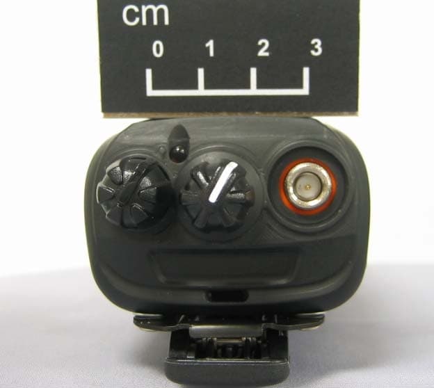
ALH443801
Dec 09, 2013UHF Digital Transceiver
Equipment Class
TNF - Licensed Non-Broadcast Transmitter Held to Face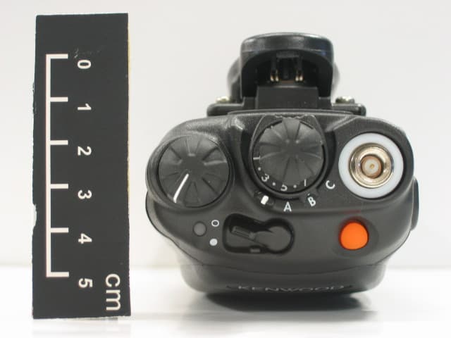
ALH468800
Oct 22, 2013PORTABLE LMR RADIO
Equipment Class
TNF - Licensed Non-Broadcast Transmitter Held to Face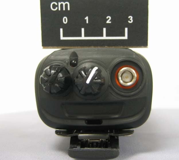
ALH443700
Aug 18, 2013VHF Digital Transceiver Models NX-240-P, NX-240-K, NX-240-M, NX-240-M2, NX-240V-K
Equipment Class
TNF - Licensed Non-Broadcast Transmitter Held to Face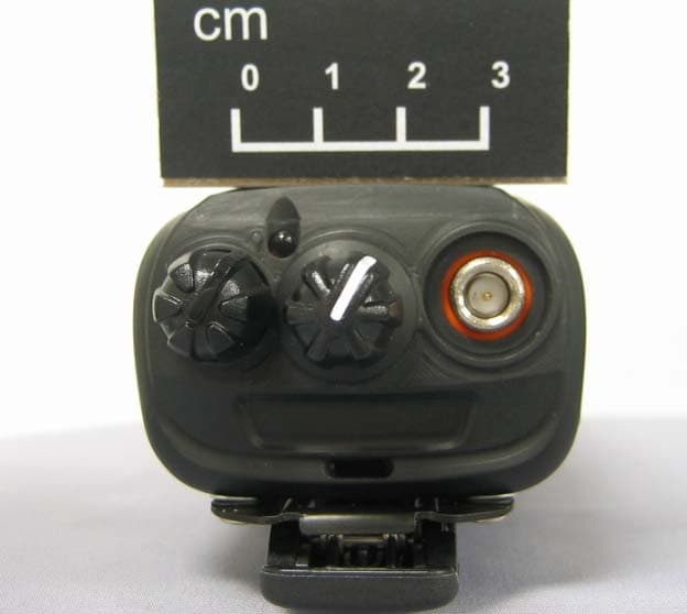
ALH443800
Aug 07, 2013Model NX-340 Digital Transceiver
Equipment Class
TNF - Licensed Non-Broadcast Transmitter Held to Face