ALH459700Models PKT-03-K, PKT-03-M
Kenwood USA Corporation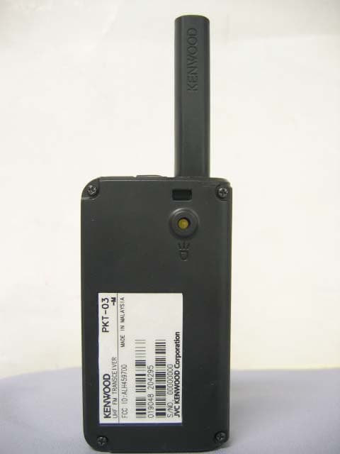
Click to zoom
Application Details
- Equipment Class
- TNF - Licensed Non-Broadcast Transmitter Held to Face
- Date of Grant
- Jul 29, 2013
- Application Purpose
- Original Equipment
- Date of Application
- Jul 28, 2013
- Equipment Note
- Models PKT-03-K, PKT-03-M
- Frequency Range
- 440.00000000 - 480.00000000
- Company
- Kenwood USA Corporation
- Country
- United States
Documents & Files
Document Text
Text extracted from the exhibit documents filed with the FCC. Open a document above to read the original.
Users Manual
UHF FM TRASCEIVER INSTRUCTION MANUAL © B62‑2525‑00 (M) Thank You We are grateful you have chosen KENWOOD for your land mobile radio applications. noTices To The user ◆ Government law prohibits the operation of unlicensed radio transmitters within the territories under government control. ◆ Illegal operation is punishable by fine and/or imprisonment. ◆ Refer service to qualified technicians only. Safety: It is important that the operator is aware of, and understands, hazards common to the operation of any transceiver. PrecauTions • Do not charge the battery pack when they are wet. • Ensure that there are no metallic items located between the transceiver and the battery pack. • If the transceiver part is damaged, do not touch the damaged parts. • If an earphone is connected to the transceiver, reduce the transceiver volume. Pay attention to the volume level when turning the squelch off. • Do not place the earphone cable around your neck while near machinery that may catch the cable. • Do not place the transceiver on unstable surfaces. If the transceiver switches OFF/ON as a result of falling or hard impact, the volume and channel configurations may reset. • Ensure that the end of the antenna does not touch your eyes. • Do not immerse the transceiver in water. • Always switch the transceiver power off before installing optional accessories. • Do not look directly at the LED light while it is lit. Information concerning the battery pack: The battery pack includes flammable objects such as organic solvent. Mishandling may cause the battery to rupture producing flames or extreme heat, deteriorate, or cause other forms of damage to the battery. Please observe the following prohibitive matters. • Do not disassemble or reconstruct the battery! The battery pack has a safety function and protection circuit to avoid danger. If they suffer serious damage, the battery may generate heat or smoke, rupture, or burst into flame. • Do not short-circuit the battery! Do not join the + and – terminals using any form of metal (such as a paper clip or wire). Do not carry or store the battery pack in containers holding metal objects (such as wires, chain‑necklace or hairpins). If the battery pack is short‑circuited, excessive current will flow and the battery may generate heat or smoke, rupture, or burst into flame. It will also cause metal objects to heat up. • Do not incinerate or apply heat to the battery! If the insulator is melted, the gas release vent or safety function is damaged, or the electrolyte is ignited, the battery may generate heat or smoke, rupture, or burst into flame. • Do not leave the battery near fire, stoves, or other heat generators (areas reaching over 60°C)! If the polymer separator is melted due to high temperature, an internal short‑circuit may occur in the individual cells and the battery may generate heat or smoke, rupture, or burst into flame. • Do not immerse the battery in water or get it wet by other means! If the battery’s protection circuit is damaged, the battery may charge at extreme current (or voltage) and an abnormal chemical reaction may occur. The battery may generate heat or smoke, rupture, or burst into flame. • Do not charge the battery near fire or under direct sunlight! If the battery’s protection circuit is damaged, the battery may charge at extreme current (or voltage) and an abnormal chemical reaction may occur. The battery may generate heat or smoke, rupture, or burst into flame. • Use only the specified charger and observe charging requirements! If the battery is charged in unspecified conditions (under high temperature over the regulated value, excessive high voltage or current over regulated value, or with a remodeled charger), it may overcharge or an abnormal chemical reaction may occur. The battery may generate heat or smoke, rupture, or burst into flame. • Do not pierce the battery with any object, strike it with an instrument, or step on it! This may break or deform the battery, causing a short‑circuit. The battery may generate heat or smoke, rupture, or burst into flame. • Do not jar or throw the battery! An impact may cause the battery to leak, generate heat or smoke, rupture, and/or burst into flame. If the battery’s protection circuit is damaged, the battery may charge at an abnormal current (or voltage), and an abnormal chemical reaction may occur. The battery may generate heat or smoke, rupture, or burst into flame. • Do not use the battery pack if it is damaged in any way! The battery may generate heat or smoke, rupture, or burst into flame. • Do not solder directly onto the battery! If the insulator is melted or the gas release vent or safety function is damaged, the battery may generate heat or smoke, rupture, or burst into flame. • Do not reverse the battery polarity (and terminals)! When charging a reversed battery, an abnormal chemical reaction may occur. In some cases, an unexpected large amount of current may flow upon discharging. The battery may generate heat or smoke, rupture, or burst into flame. • Do not reverse-charge or reverse-connect the battery! The battery pack has positive and negative poles. If the battery pack does not smoothly connect with a charger or operating equipment, do not force it; check the polarity of the battery. If the battery pack is reverse‑connected to the charger, it will be reverse‑charged and an abnormal chemical reaction may occur. The battery may generate heat or smoke, rupture, or burst into flame. • Do not touch a ruptured and leaking battery! If the electrolyte liquid from the battery gets into your eyes, wash your eyes with fresh water as soon as possible, without rubbing your eyes. Go to the hospital immediately. If left untreated, it may cause eye‑problems. • Do not charge the battery for longer than the specified time! If the battery pack has not finished charging even after the regulated time has passed, stop it. The battery may generate heat or smoke, rupture, or burst into flame. • Do not place t…
Text truncated - open the document above for the full version.
Cover Letter(s)
Kenwood USA Corporation 3970 Johns Creek Court, Suwanee, GA 30024 (678) 474-4700 June 28, 2013 Federal Communications Commission Authorization & Evaluation Division 7345 Oakland Mills Road Columbia, Maryland 21046 To Whom It May Concern: This letter will authorize Compliance Testing LLC to act as our Agent in all FCC matters. This appointment is effective until otherwise notified by us. This is to advise that we are in full compliance with the Anti-Drug Abuse Act. The Applicant is not subject to a denial of federal benefits pursuant to Section 5301 of the Anti-Drug Abuse Act of 1988, 21 USC 862, and no party to the application is subject to a denial of federal benefits pursuant to that section. Sincerely,
Cover Letter(s)
June 28, 2013 Federal Communications Commission 7435 Oakland Mills Road Columbia, MD 21046 Attn: Reviewing Engineer RE: CONFIDENTIALITY REQUEST FOR MODEL: PKT-03-K, PKT-03-M, FCC ID: ALH459700 To Whom It May Concern: This letter serves as an official request for permanent confidentiality pursuant to 47 CFR Section 0.459 of the Commission Rules. We have requested that the Block Diagram, Schematic Diagrams, Circuit Description, Active Devices and Tuning Procedure required to be submitted with this application be withheld from public review. The documents are company proprietary information that should never get into the possession of our competition. Please contact me if you require any additional information. Sincerely,
Cover Letter(s)
June 28, 2013 Federal Communications Commission 7435 Oakland Mills Road Columbia, MD 21046 Attn: Reviewing Engineer Subject: Justify Extended Frequency Range for MODEL: PKT-03-K, PKT-03-M, FCC ID: ALH459700. To Whom It May Concern: This letter serves justification for extended frequencies This device has design capability to operate in the frequency band 440 to 480 MHz and complies with 47 CFR Part 90.203(e), in that the operator cannot directly program the transit frequencies using the normally accessible external controls. Please note that Licensed End Users do not have access to any external controls that will allow them to program the equipment. Equipment programming is the responsibility of KENWOOD approved Service Agents. In addition to Parts 90 usage, this device is utilized in systems such as Federal and Public Safety agencies, e.g. police, fire, and emergency medical, etc. as indicated in the following table: Table 1 – Frequency Range and Rule Parts - (47 CFR Part 2.106) It is understood that a grant note code may be added to the grant which indicates this required operation. In addition, we acknowledge that it is a violation of FCC rules if the device operates on unauthorized frequencies. Please contact me if you require any additional information. Sincerely, Freq. Range (MHz) Part 90 Federal Customers 440.000 - 454.000 x 454.000 - 456.000 x 456.000 - 462.5375 x 462.5375-462.7375 x 462.7375-467.5375 x 467.5375-467.7375 x 467.7375-480.000 x
Cover Letter(s)
Page 1 of 1 FCC ID: ALH459700 IC ID: N/A CT Project: TCB-p1340012 From: Chris Harvey Date: 7/22/2013 You are listed as the Technical Contact for the above referenced TCB application. The following item(s) need(s) to be resolved before the review can be continued: CT – Amanda is listed only under Section 2(e) as the Non-Technical contact 1. Please update the FCC Test report to include the FCC ID number of this application. CT – Updated report to include FCC ID 2. Please update page 6 of 27 of the test report to correct the typo of rule section 2.1079 to be 2.1049. Additionally, page 7 of the report should reference FCC 2.1049 for the Occupied Bandwidth measurements. CT - Updated 3. Your test report documents testing in accordance with ANSI C63.4:2009, but this device is a licensed transceiver subject to the measurements of ANSI/TIA 603C. Please update your test report to reference the correct test measurements. CT - Updated 4. Please also provide an FCC Pt. 90 Check Sheet. CT - Provided Response by: John Erhard / Amanda Reed Submitted by: Amanda Reed Date: 7/23/2013
External Photos
PKT-03-K, PKT-03-M FCC ID: ALH459700 Front V iew PKT-03-K, PKT-03-M FCC ID: ALH459700 Rear View PKT-03-K, PKT-03-M FCC ID: ALH459700 Left View Right View PKT-03-K, PKT-03-M FCC ID: ALH459700 Top View ] Bottom V iew
ID Label/Location Info
PKT-03-K, PKT-03-M FCC ID: ALH459700 PKT-03-K, PKT-03-M FCC ID: ALH459700 PKT-03-K, PKT-03-M FCC ID: ALH459700
Internal Photos
PKT-03-K, PKT-03-M FCC ID: ALH459700 NX-420-K Display Unit PKT-03-K, PKT-03-M FCC ID: ALH459700 PKT-03-K, PKT-03-M FCC ID: ALH459700
RF Exposure Info
802 N. Twin Oaks Valley Road, Suite 105 • San Marcos, CA 92069 • U.S.A. TEL (760) 471-2100 • FAX (760) 471-2121 http://www.rfexposurelab.com CERTIFICATE OF COMPLIANCE SAR EVALUATION Kenwood USA Corporation Dates of Test: June 22, 2013 3970 Johns Creek Court, Suite 100 Test Report Number: SAR.20130603 Suwanee, GA 30024 This wireless mobile and/or portable device has been shown to be compliant for localized specific absorption rate (SAR) for uncontrolled environment/general exposure limits specified in ANSI/IEEE Std. C95.1-1992 and had been tested in accordance with the measurement procedures specified in IEEE 1528-2003, and OET Bulletin 65 Supp. C (See test report). I attest to the accuracy of the data. All measurements were performed by myself or were made under my supervision and are correct to the best of my knowledge and belief. I assume full responsibility for the completeness of these measurements and vouch for the qualifications of all persons taking them. RF Exposure Lab, LLC certifies that no party to this application is subject to a denial of Federal benefits that includes FCC benefits pursuant to Section 5301 of the Anti-Drug Abuse Act of 1988, 21 U.S.C. 853(a). Jay M. Moulton Vice President Certificate # 2387.01 FCC ID: ALH459700 Model(s): PKT-03-K, PKT-03-M (Both Models are Electrically Identical) Test Sample: Engineering Unit Same as Production Serial Number: Eng 1 Equipment Type: Push-To-Talk Handheld Radio for Occupational Use Classification: Portable Transmitter Next to Face and Body TX Frequency Range: 440 – 480 MHz Frequency Tolerance: ± 2.5 ppm Maximum RF Output: 450 MHz – 31.76 dB Conducted Signal Modulation: FM Body Worn Accessories: No Body Worn Accessories are Offered Audio Accessories: Model MR-L30 Antenna Type: Integral Antenna (Only one available) Battery: Standard (Model KNB-71L) Application Type: Certification FCC Rule Parts: Part 2, 90 KDB Test Methodology: KDB 447498 D01 v05, KDB 643646 D01 v01r01 Maximum SAR Value: Face – 0.54 W/kg (Reported); Body – 5.11 W/kg (Reported) Separation Distance: 25 mm for Face; 0 mm for Body © 2013 RF Exposure Lab, LLC This report shall not be reproduced except in full without the written approval of RF Exposure Lab, LLC. FCC ID: ALH459700 Table of Contents 1. Introduction ........................................................................................................................ 3 SAR Definition [5] ................................................................................................................... 4 2. SAR Measurement Setup ................................................................................................... 5 Robotic System ...................................................................................................................... 5 System Hardware ................................................................................................................... 5 System Electronics ................................................................................................................. 6 Probe Measurement System .................................................................................................. 6 3. Probe and Dipole Calibration .............................................................................................11 4. Phantom & Simulating Tissue Specifications .....................................................................12 Head & Body Simulating Mixture Characterization ................................................................12 Device Holder .......................................................................................................................12 5. ANSI/IEEE C95.1 – 1992 RF Exposure Limits [2] ..............................................................13 Uncontrolled Environment .....................................................................................................13 Controlled Environment .........................................................................................................13 6. Measurement Uncertainty .................................................................................................14 7. System Validation..............................................................................................................15 Tissue Verification .................................................................................................................15 Test System Verification ........................................................................................................15 8. SAR Test Data Summary ..................................................................................................16 Procedures Used To Establish Test Signal ...........................................................................16 Device Test Condition ...........................................................................................................16 SAR Data Summary – Head SAR in Front of Face Measurements .......................................20 SAR Data Summary – Body SAR Measurements – Standard Battery ...................................21 9. Test Equipment List ...........................................................................................................22 10. Conclusion ....................................................................................................................23 11. References ....................................................................................................................24 Appendix A – System Validation Plots and Data .......................................................................25 Appendix B – SAR Test Data Plots ...........................................................................................30 Appendix C – SAR Test Setup Photos ......................................................................................33 Appendix D – Probe Calibration Data Sheets ....................…
Text truncated - open the document above for the full version.
Test Report
p1340012_FCC_Part 90_Rev 2.0 Page 1 of 27 Test Report Prepared for: Kenwood USA Corporation Model: PKT-03-K / PKT-03-M Description: UHF FM TRANSCEIVER FCC ID: ALH459700 To FCC Part 90 Date of Issue: June 24, 2013 On the behalf of the applicant: Kenwood USA Corporation Communications Division 3970 Johns Creek Court Suwanee, GA 30024 Attention of: Joel Berger, Research & Development Ph: (678) 474-4722 E-Mail: [email protected] Prepared By Compliance Testing, LLC 3356 N San Marcos Pl, Suite 107 Chandler, AZ 85225-7176 (866) 311-3268 phone / (480) 926-3598 fax www.compliancetesting.com Project No: p1340012 John Erhard Project Test Engineer This report may not be reproduced, except in full, without written permission from Compliance Testing All results contained herein relate only to the sample tested p1340012_FCC_Part 90_Rev 2.0 Page 2 of 27 Test Report Revision History Revision Date Revised By Reason for Revision 1.0 June 24, 2013 John Erhard Original Document 2.0 July 23, 2013 Amanda Reed Added FCC ID, corrected Model name, corrected rule section typos p1340012_FCC_Part 90_Rev 2.0 Page 3 of 27 Table of Contents Description Page Standard Test Conditions and Engineering Practices 6 Test Result Summary 7 Carrier Output Power (Conducted) 8 Conducted Spurious Emissions 9 Field Strength of Spurious Radiation 13 Emission Masks (Occupied Bandwidth) 16 Transient Frequency Behavior 20 Audio Low Pass Filter (Voice Input) 22 Audio Frequency Response 23 Modulation Limiting 24 Frequency Stability 25 Necessary Bandwidth Calculations 26 p1340012_FCC_Part 90_Rev 2.0 Page 4 of 27 ILAC / A2LA Compliance Testing, LLC, has been accredited in accordance with the recognized International Standard ISO/IEC 17025:2005. This accreditation demonstrates technical competence for a defined scope and the operation of a laboratory quality management system (refer joint ISO-ILAC-IAF Communiqué dated January 2009) The tests results contained within this test report all fall within our scope of accreditation, unless noted below. Please refer to http://www.compliancetesting.com/labscope.html for current scope of accreditation. Testing Certificate Number: 2152.01 FCC OATS Reg, #933597 IC Reg. #2044A-1 Non-accredited tests contained in this report: N/A p1340012_FCC_Part 90_Rev 2.0 Page 5 of 27 The Applicant has been cautioned as to the following: 15.21: Information to the User The user’s manual or instruction manual for an intentional radiator shall caution the user that changes or modifications not expressly approved by the party responsible for compliance could void the user’s authority to operate the equipment. 15.27(a): Special Accessories Equipment marketed to a consumer must be capable of complying with the necessary regulations in the configuration in which the equipment is marketed. Where special accessories, such as shielded cables and/or special connectors are required to enable an unintentional or intentional radiator to comply with the emission limits in this part, the equipment must be marketed with, i.e. shipped and sold with, those special accessories. However, in lieu of shipping or packaging the special accessories with the unintentional or intentional radiator, the responsible party may employ other methods of ensuring that the special accessories are provided to the consumer, without an additional charge. Information detailing any alternative method used to supply the special accessories for a grant of equipment authorization or retained in the verification records, as appropriate. The party responsible for the equipment, as detailed in § 2.909 of this chapter, shall ensure that these special accessories are provided with the equipment. The instruction manual for such devices shall include appropriate instructions on the first page of text concerned with the installation of the device that these special accessories must be used with the device. It is the responsibility of the user to use the needed special accessories supplied with the equipment. p1340012_FCC_Part 90_Rev 2.0 Page 6 of 27 Test and Measurement Data All tests and measurement data shown were performed in accordance with FCC Rules and Regulations, Volume II, Part 2, Subpart J, Sections 2.947, 2.1033(c), 2.1041, 2.1046, 2.1047, 2.1049, 2.1051, 2.1053, 2.1055, 2.1057, and the following individual Parts of 22 and 90. Standard Test Conditions and Engineering Practices Except as noted herein, the following conditions and procedures were observed during the testing. In accordance with ANSI/TIA 603C, and unless otherwise indicated in the specific measurement results, the ambient temperature of the actual EUT was maintained within the range of 10° to 40°C (50° to 104°F) unless the particular equipment requirements specify testing over a different temperature range. Also, unless otherwise indicated, the humidity levels were in the range of 10% to 90% relative humidity. Environmental Conditions Temp (ºC) Humidity (%) Pressure (mbar) 24.8 - 29.9 27.1 - 32.6 961.2 - 966.2 Measurement results, unless otherwise noted, are worst-case measurements. EUT Description Model: PKT-03-K / PKT-03-M Description: UHF FM Transceiver Firmware: N/A Software: N/A Additional Information: The EUT is a low cost push to talk occupational radio. EUT Operation during Tests The EUT was in a normal operating condition for testing. Both a radiated and conducted sample were provided. Accessories: None Cables: None Modifications: None p1340012_FCC_Part 90_Rev 2.0 Page 7 of 27 Test Result Summary Specification Test Name Pass, Fail, N/A Comments 2.1046 Carrier Output Power (Conducted) Pass 2.1051 Unwanted Emissions (Transmitter Conducted) Pass 2.1053 Field Strength of Spurious Radiation Pass 90.210, 2.1049 Emission Masks (Occupied Bandwidth) Pass 2.1047 Audio Low Pass Filter (Voice Input) Pass 2.1047 Audio Frequency Response Pass 2.1047(a) Modulation Limiting Pass 90.213 Frequency Stability (Temperature Variation) Pass 90.213 Frequency Stability (Voltage Variation) Pass 90.214 Transie…
Text truncated - open the document above for the full version.
Test Setup Photos
PKT-03-K, PKT-03-M FCC ID: ALH459700 Test Setup Photos RF Conducted PKT-03-K, PKT-03-M FCC ID: ALH459700 Test Setup Photos RF Radiated
Contact Information
Applicant
Angelina Seay(Regulatory Support Engineer)
Test Firm
Compliance Testing, LLCMichael Schafer
Technical Specifications
| # | Rule Parts | Frequency Range | Power Output | Emission | Tolerance |
|---|---|---|---|---|---|
| 1 | 90 | 440 MHz - 480 MHz | 1.5 W | 11K0F3E | 2.5000000000 ppm |
Other Applications from Kenwood USA Corporation
ALH442000
Jul 06, 2014Push to talk radio.
Equipment Class
DXX - Part 15 Low Power Communication Device Transmitter
ALH443801
Dec 09, 2013UHF Digital Transceiver
Equipment Class
TNF - Licensed Non-Broadcast Transmitter Held to Face
ALH468800
Oct 22, 2013PORTABLE LMR RADIO
Equipment Class
TNF - Licensed Non-Broadcast Transmitter Held to Face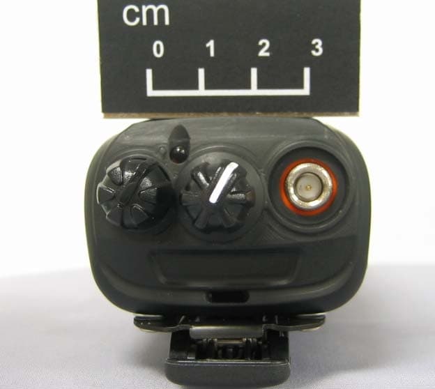
ALH443700
Aug 18, 2013VHF Digital Transceiver Models NX-240-P, NX-240-K, NX-240-M, NX-240-M2, NX-240V-K
Equipment Class
TNF - Licensed Non-Broadcast Transmitter Held to Face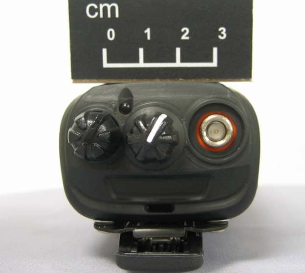
ALH443800
Aug 07, 2013Model NX-340 Digital Transceiver
Equipment Class
TNF - Licensed Non-Broadcast Transmitter Held to Face