AMB-BE02721200 Mbps 11ac Wireless Dual Band USB Adapter
BearExtender
Click to zoom
Application Details
- Equipment Class
- NII - Unlicensed National Information Infrastructure TX
- Date of Grant
- Oct 24, 2013
- Application Purpose
- Original Equipment
- Date of Application
- Oct 24, 2013
- Equipment Note
- 1200 Mbps 11ac Wireless Dual Band USB Adapter
- Frequency Range
- 5210.00000000 - 5210.00000000
- Company
- BearExtender
- Country
- United States
Documents & Files
Document Text
Text extracted from the exhibit documents filed with the FCC. Open a document above to read the original.
Users Manual
Thank you for purchasing BearExtender! Please select your version of Mac OS X to begin: Mac OS X 10.8 Mountain Lion Mac OS X 10.7 Lion Mac OS X 10.6 Snow Leopard Mac OS X 10.5 Leopard Checking your version of Mac OS X Go to the Apple Menu, and choose “About This Mac.” Then look for the version number of Mac OS X you have installed. Step 1: Install Open the Mac OS X Mountain Lion folder on the CD, then double click “Install”. When the installation has finished, restart your Mac. Step 2: Plug in BearExtender Connect the USB cable directly to your Mac. If you are using a Macintosh desktop computer, do not use the low power USB ports on the keyboard. Step 3: Turn Off Wi-Fi If your Mac has a built-in Wi-Fi (AirPort) card, please turn it off while using BearExtender. Step 4: Join a network from the BearExtender window Select your network from the list and click “Connect”. Once you are connected, you can close or minimize this window. Use this window to scan and connect to networks in place of the AirPort (Wi-Fi) menu. Congratulations! BearExtender is now ready for use. If you need help, please view the Troubleshooting page or contact us. Next Steps Learn how to create a Favorite Network >> Using the BearExtender Window The BearExtender window will automatically open whenever BearExtender is plugged in. BearExtender will then perform a scan of nearby networks and connect to the strongest open network. Connecting to a Network Select a network from the list and click Connect. If your network does not appear in the list immediately, click Refresh. The signal strength is displayed as a percent out of 100. Once you are connected to a network, you can minimize or close the BearExtender window. Creating a Favorite Network You can save frequently accessed Wi-Fi network passwords, so you will not need to re-enter the password each time. 1. Click once on the network in the “Networks” list. 2. Click Add to Profile 3. Enter the network password (network key), then click “OK”. Comparing signal strength To compare BearExtender’s signal strength with your internal AirPort (Wi-Fi) card, download a scanning program such as iStumbler. iStumbler and other scanning programs can display your internal AirPort card’s signal strength as a percentage for comparison with BearExtender. Changing the Country Region Code The country region code is set to channels 1-11 by default for use in the United States. In other parts of the world, you may be able to use additional channels, such as 1-13 in most European countries. Channel 14 is currently limited to only a few countries such as Japan. Disabling BearExtender To disable BearExtender and use your internal Wi-Fi (AirPort) card, click “Turn Radio Off” on the “Link Status” tab. © 2013 BearExtender | Apple, Macintosh, and Airport are registered trademarks of Apple Inc. | FCC Notice Any changes or modifications not expressly approved by the responsible party could void the user’s authority to operate this equipment. FCC Radiation Exposure Statement This equipment complies with FCC RF radiation exposure limits set forth for an uncontrolled environment. This transmitter must not be operated with any other antenna or transmitter and is designed for indoor use. This equipment should be placed a minimum of 20 centimeters from the human body when in use. The USB cable included with this product is 60 centimeters in length. This equipment complies with Part 15 of the FCC Rules. Operation is subject to the following two conditions: (1) This device may not cause harmful interference, and (2) This device must accept any interference received, including interference that may cause undesired operation. © 2013 BearExtender | Apple, Macintosh, and Airport are registered trademarks of Apple Inc. | Optimizing Performance Although BearExtender has a powerful transceiver and external antenna, you may still desire a stronger signal in certain environments. The primary culprit is interference. 802.11b, 802.11g, 802.11n and 802.11ac share radio frequencies with devices such as cordless phones, cellular phones and microwaves. Being in the proximity of any combination of these devices will result in interference. Solid concrete walls, large metallic appliances can also produce interference passively by deflecting Wi-Fi signals. If you are an RV or Marine user, try using BearExtender outside or above any large metal plating in your vehicle or boat. Aluminum and other metals reflect Wi-Fi signals. To minimize interference, try the following: Change BearExtender’s antenna position between horizontal and vertical. BearExtender’s antenna has unique sensing properties in the horizontal and vertical direction. By changing the angle of the antenna, you can direct BearExtender to focus on specific networks. Reposition yourself Move away from devices that may cause interference and thick solid walls that may reflect Wi-Fi signals. Change your Wireless Router’s broadcast channel. Wireless routers can communicate on different channels. Many wireless routers ship by default locked onto one channel. By changing your wireless router to broadcast on a less crowded channel, you can maximize speed and decrease interference. This usually fixes the problem if you are located in a high density area, such as a multi-level apartment building. Consult your wireless router’s manual for instructions. In general, changing the position of BearExtender’s antenna and relocating yourself should improve your connection. Troubleshooting If you need further assistance, please do not hesitate to contact us. Step 1: Turn off AirPort (Wi-Fi) If your Mac has an internal Wi-Fi card, turn it off when using BearExtender. Step 2: Refresh Refresh your web browser a few times. If your Mac has been sleeping, BearExtender takes a few seconds to scan and re-connect. Step 3: Unplug and Restart Unplug the USB cable then restart your Mac and try again. Step 4: Remove Saved Networks If you have created any Favorite Networks, please delete them on th…
Text truncated - open the document above for the full version.
Attestation Statements
BearExtender ADD: 1406 Henry Street,Berkeley,California,94709,USA Tel: (678) 971-9367 Fax: 678-971-9367 To: Federal Communications Commission Authorization & Evaluation Division 7435 Oakland Mill Road Colambia, Maryland 21046 Declaration Date: 2013-10-24 Subject: Project number: B1310222, FCC ID: AMB-BE0272 declaration of frequency bands restriction Dear Sir or Madam: We, BearExtender, hereby declare that our product 1200Mbps 11AC Wireless Dual Band USB Adapter, Model Number: BearExtender Turbo has 4 frequency bands: 5150 MHz~5250 MHz,5250 MHz~5350MHz,5470 MHz~5725 MHz,5725 MHz~5850 MHz. These frequency bands are controlled by software, and the end user can not have the capability to activate the frequency bands. For the purpose of marketing, we will open the relevant frequency bands according to the local country electronic laws. We applied for testing only frequency bands 5150 MHz~5250 MHz, 5725 MHz~5850 MHz for the United States this time in BACL. Roland Saekow Product Development Officer
Cover Letter(s)
BearExtender ADD: 1406 Henry Street,Berkeley,California,94709,USA Tel: (678) 971-9367 Fax: 678-971-9367 FCC Authorization Date: 2013-10-15 FEDERAL COMMUNICATIONS COMMISSIONS Authorization and Evaluation Division 7435 Oakland Mills Road Columbia, MD 21046 Subject: Agent Authorization To whom it may concern: We, BearExtender, the undersigned, Hereby authorizes Bay Area Compliance Laboratories Corporation to act on its behalf in all matters relating to application for Equipment authorization, including the signing of all documents relating to these matters. All acts carried out by Bay Area Compliance Laboratories Corp. on our behalf shall have the same effect as our own action. We, the undersigned, hereby certify that we are not subject to a denial of federal benefits, that includes FCC benefits, pursuant to Section 5301 of the Anti-Drug Abuse Act of 1988, 21 U.S.C. 853(a). This authorization is valid until further written notice from the applicant. Sincerely Yours, Roland Saekow Product Development Officer
Cover Letter(s)
BearExtender ADD: 1406 Henry Street,Berkeley,California,94709,USA Tel: (678) 971-9367 Fax: 678-971-9367 Date: 2013-10-15 Federal Communications Commission Authorization and Evaluation Division 7435 Oakland Mills Road, Columbia, MD 21046 RE: Request of confidentiality for FCC ID: AMB-BE0272 To Whom It May Concern: Pursuant to Sections 0.457 and 0.459 of the Commission’s Rules (CFR 47), and Section 552 (b) (4) of the Freedom of Information Act, BearExtender hereby requests confidentiality and treatment of certain information accompanying this application. The materials contain trade secrets and proprietary information not customarily released to the public. The public disclosure of these matters might be harmful to the applicant and provide unjustified benefits to its competitors. We also hereby request Short-Term Confidentiality for 45 days after the grant as outlined in Public Notice DA 04-1705. This provision will give BearExtender temporary confidentiality of commercially sensitive information prior to product release. The requested Permanent and Short-Term Confidential exhibits are listed as follows: PERMANENT AND SHORT-TERM CONFIDENTIAL LIST Exhibit Description PERMANENT 1 Block Diagram 2 Circuit Description 3 Schematic SHORT-TERM 4 External Photos 5 Internal Photos 6 Test-Setup Photos The applicant understands that pursuant to Rule 0.457, disclosure of this application and all accompanying documentations, where applicable, will not be made public before the date of the Grant for this application. Sincerely, Roland Saekow Product Development Officer
External Photos
EXHIBIT B - EUT EXTERNAL PHOTOGRAPHS EUT— All View EUT— Port View EUT— Antenna Off View EUT—Top View EUT- Bottom View EUT - Right Side View EUT— Left Side View EUT— Antenna View EUT— Antenna Port View
ID Label/Location Info
EXHIBIT A - FCC ID LABELING AND LOCATION FCC ID Label FCC ID Label Location The label shown shall be permanently affixed at a conspicuous location on the device and be readily visible to the user at the time purchase (Labeling requirements per 2.925) Label Here
Internal Photos
EXHIBIT B - EUT EXTERNAL PHOTOGRAPHS EUT- Uncover View EUT- Cover Off View EUT-Main Board Top With Shielding View EUT-Main Board Top Without Shielding View EUT-Main Board Bottom View EUT- RF Module View
RF Exposure Info
Bay Area Compliance Laboratories Corp. (Dongguan) Report No.: R2DG130930001-00B FCC Part 15.407 Page 10 of 138 FCC §15.407(f) & §1.1310 & §2.1091- MAXIMUM PERMISSIBLE EXPOSURE (MPE) Applicable Standard According to subpart 15.407(f)and subpart §1.1310, systems operating under the provisions of this section shall be operated in a manner that ensures that the public is not exposed to radio frequency energy level in excess of the Commission’s guidelines. Limits for Maximum Permissible Exposure (MPE) (§1.1310, §2.1091) (B) Limits for General Population/Uncontrolled Exposure Frequency Range (MHz) Electric Field Strength (V/m) Magnetic Field Strength (A/m) Power Density (mW/cm 2 ) Averaging Time (minutes) 0.3–1.34 614 1.63 *(100) 30 1.34–30 824/f 2.19/f *(180/f²) 30 30–300 27.5 0.073 0.2 30 300–1500 / / f/1500 30 1500–100,000 / / 1.0 30 f = frequency in MHz; * = Plane-wave equivalent power density; According to §1.1310 and §2.1091 RF exposure is calculated. Calculated Formulary: Predication of MPE limit at a given distance S = PG/4πR² = power density (in appropriate units, e.g. mW/cm 2 ); P = power input to the antenna (in appropriate units, e.g., mW); G = power gain of the antenna in the direction of interest relative to an isotropic radiator, the power gain factor, is normally numeric gain; R = distance to the center of radiation of the antenna (appropriate units, e.g., cm); Calculated Data: Mode Frequency (MHz) Antenna Gain Conducted Power Evaluation Distance (cm) Power Density (mW/cm 2 ) MPE Limit (mW/cm 2 ) (dBi) (numeric)(dBm)(mW) 802.11a 5180 1.5 1.41 13.5122.4420 0.006 1.0 802.11n ht20 5180 1.5 1.41 13.2521.1320 0.006 1.0 802.11n ht40 5190 1.5 1.41 10.4611.1220 0.003 1.0 802.11ac20 5180 1.5 1.41 13.1120.4620 0.006 1.0 802.11ac40 5190 1.5 1.41 13.1920.8420 0.006 1.0 802.11ac80 5210 1.5 1.41 10.2910.6920 0.003 1.0 Result: The device meet FCC MPE at 20 cm distance
Test Report
Note: This test report is prepared for the customer shown above and for the device described herein. It may not be duplicated or used in part without prior written consent from Bay Area Compliance Laboratories Corp. This report must not be used by the customer to claim product certification, approval, or endorsement by NVLAP*, or any agency of the Federal Government. * This report may contain data that are not covered by the NVLAP accreditation and shall be marked with an asterisk “★” (Rev.2), This report is valid only with a valid digital signature. The digital signature may be available only under the Adobe software above version 7.0. FCC PART 15.407 TEST REPORT For BearExtender 1406 Henry Street, Berkeley, California, 94709, USA Report Type: Original Report Product Type: 1200Mbps 11AC Wireless Dual Band USB Adapter Test En gineer: Leon Chen Re port Number: R2DG130930001-00B Re port Date: 2013-10-15 Reviewed By: Ivan Cao RF Leade r Test Laboratory: Bay Area Compliance Laboratories Corp. (Dongguan) No.69 Pulongcun, Puxinhu Industrial Zone, Tangxia, Dongguan, Guangdong, China Tel: +86-769-86858888 Fax: +86-769-86858891 www.baclcorp.com.cn FCC ID: AMB-BE0272 Bay Area Compliance Laboratories Corp. (Dongguan) Report No.: R2DG130930001-00B FCC Part 15.407 Page 2 of 138 TABLE OF CONTENTS GENERAL INFORMATION ....................................................................................................................................... 4 PRODUCT DESCRIPTION FOR EQUIPMENT UNDER TEST (EUT) ..................................................................................... 4 ANTENNA INFORMATION .............................................................................................................................................. 4 OBJECTIVE ................................................................................................................................................................... 4 RELATED SUBMITTAL(S)/GRANT(S) ............................................................................................................................. 4 TEST METHODOLOGY .................................................................................................................................................. 4 TEST FACILITY ............................................................................................................................................................. 5 SYSTEM TEST CONFIGURATION .......................................................................................................................... 6 DESCRIPTION OF TEST CONFIGURATION ...................................................................................................................... 6 EQUIPMENT MODIFICATIONS ....................................................................................................................................... 6 EUT EXERCISE SOFTWARE .......................................................................................................................................... 7 SUPPORT EQUIPMENT LIST AND DETAILS .................................................................................................................... 8 EXTERNAL CABLE ........................................................................................................................................................ 8 BLOCK DIAGRAM OF TEST SETUP ................................................................................................................................ 8 SUMMARY OF TEST RESULTS ............................................................................................................................... 9 FCC §15.407(f) & §1.1310 & §2.1091- MAXIMUM PERMISSIBLE EXPOSURE (MPE) ....................................... 10 APPLICABLE STANDARD ............................................................................................................................................ 10 FCC §15.203 – ANTENNA REQUIREMENT .......................................................................................................... 11 APPLICABLE STANDARD ............................................................................................................................................ 11 ANTENNA CONNECTOR CONSTRUCTION .................................................................................................................... 11 FCC §15.407 (b) (6) §15.207 (a) – CONDUCTED EMISSIONS ............................................................................. 12 APPLICABLE STANDARD ............................................................................................................................................ 12 MEASUREMENT UNCERTAINTY .................................................................................................................................. 12 EUT SETUP ................................................................................................................................................................ 12 EMI TEST RECEIVER SETUP ....................................................................................................................................... 13 CORRECTED AMPLITUDE & MARGIN CALCULATION ................................................................................................. 13 TEST EQUIPMENT LIST AND DETAILS ......................................................................................................................... 13 TEST PROCEDURE ...................................................................................................................................................... 14 TEST RESULTS SUMMARY .......................................................................................................................................... 14 TEST DATA ........................................................................................................................…
Text truncated - open the document above for the full version.
Test Setup Photos
EXHIBIT D - TEST SETUP PHOTOGRAPHS Conducted Emission - Front View Conducted Emission - Side View Radiated Emission – Front View (Below 1GHz) Radiated Emission – Rear View (Below 1GHz) Radiated Emission – Front View (Above 1GHz Distance 1.5m) Radiated Emission – Rear View (Above 1GHz Distance 1.5m)
Contact Information
Applicant
Roland Saekow(Co-founder)
Test Firm
Bay Area Compliance Laboratories Corp. (Dongguan)John Chan
[email protected]86-769-86858888
Technical Specifications
| # | Rule Parts | Frequency Range | Power Output |
|---|---|---|---|
| 4 | 15E | 5.21 GHz - 5.21 GHz | 10.70 mW |
Other Applications from BearExtender

AMB-BE300
Jun 07, 2015BearExtender PC
Equipment Class
DTS - Digital Transmission System
AMB-JN7
Aug 29, 2013Wireless USB Adapter
Equipment Class
DTS - Digital Transmission System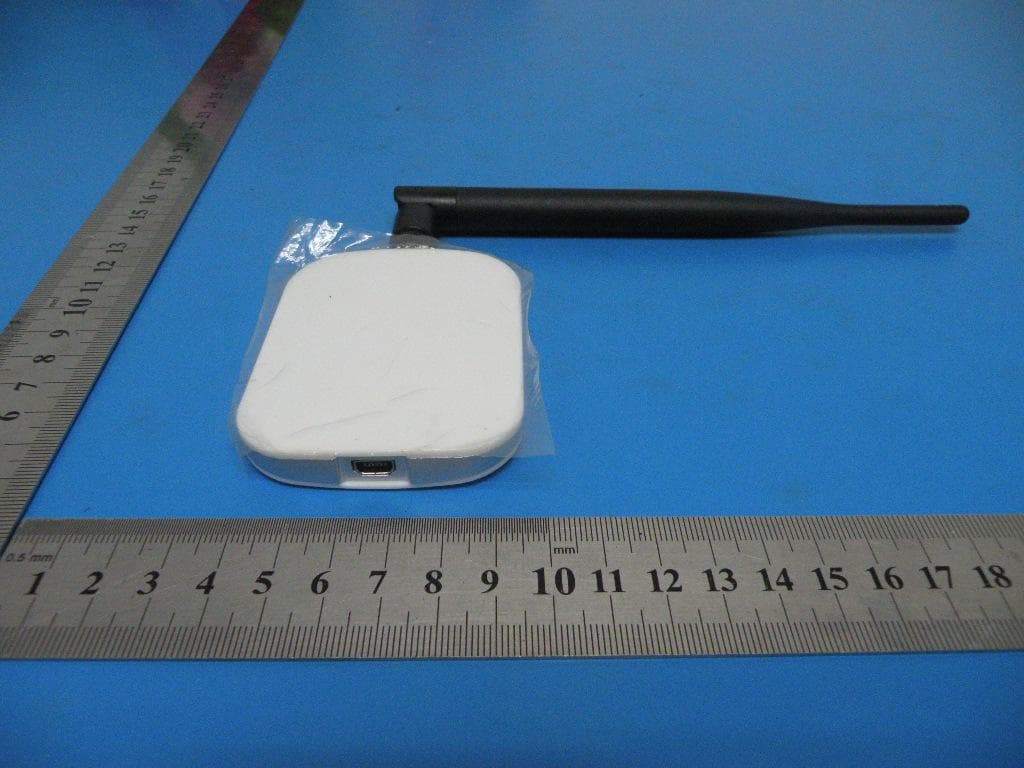
AMBJN7
Aug 01, 2013Wireless USB Adapter
Equipment Class
DTS - Digital Transmission System