AMB-BE300BearExtender PC
BearExtender
Click to zoom
Application Details
- Equipment Class
- DTS - Digital Transmission System
- Date of Grant
- Jun 07, 2015
- Application Purpose
- Original Equipment
- Date of Application
- Jun 07, 2015
- Equipment Note
- BearExtender PC
- Frequency Range
- 2412.00000000 - 2462.00000000
- Company
- BearExtender
- Country
- United States
Documents & Files
Document Text
Text extracted from the exhibit documents filed with the FCC. Open a document above to read the original.
Users Manual
Windows XP Guide Step 1: Install Software Insert the CD-ROM into your computer. When the Autorun menu appears, click “Windows XP”. If the Autorun menu does not appear, Navigate to your CD drive, then right-click it and select “Open.” Then double click the Setup program to begin. Once the software has installed, connect BearExtender PC’s USB cable directly to your computer. A popup will appear in the bottom right corner of your screen. A second popup will confirm that the installation has completed. Do not connect BearExtender PC’s USB cable yet If you have already connected it, please disconnect it. It may take up to 30 seconds for the Autorun menu to appear, depending on the speed of your CD drive. Depending on your version of Windows XP Service Pack, you may not see a message saying the installation has completed. Instead, you may see the Windows Hardware wizard. If the Windows Hardware wizard appears on your screen, on the first screen select "No, not this time." Then on the next screen select "Install software automatically (Recommended)". The hardware wizard will then complete the installation. Depending on your processor speed, this process can take up to 2 minutes. Once completed, click the Finish button and proceed to the next step. Step 2: Disable your Built-in Wi-Fi card If your computer has a built-in Wi-Fi card, please disable it. Some laptops have a ON/OFF switch for disabling the built-in Wi-Fi card. If your computer does not have a switch, go to Control Panel > Network Connections. Then right-click your built-in Wi-Fi card and click “Disable.” You can repeat this step and select “Enable” when you wish to use your internal Wi-Fi card again. Instructions continued on next page Step 3: Scan and Join a Network Because BearExtender PC uses the built-in Windows XP interface for connecting to wireless networks, there is no new software to learn. Simply right-click on the Network icon located in the bottom right corner of your screen: Then select “View Available Networks”. A list of nearby networks will appear. Select your network and click “Connect.” You will be asked for a password if required. If you are unable to locate the Network icon, follow these steps: 1.Go to Control Panel 2.Double click “Network Connections” 3.Then right-click “Wireless Connection 2” and select “View Available Wireless Networks” Congratulations You have finished setting up BearExtender PC. If you need additional help, please see the Troubleshooting section or contact us using the information at the end of this guide. The digit after "Wireless Network Connection" may vary if you have previously had other Wi-Fi adapters installed on your computer. Troubleshooting 1.I do not see any connection icon in the bottom right of my screen, and when I follow the instructions to go to the device in the Control Panel > Network Connections I am not able to see the device there either. Be sure you have run the Setup program from the CD in its entirety. If you have, and BearExtender PC is connected to your computer, please contact BearExtender support for further assistance. 2.The specifications for this product say 150 Mbps max speed, but the Connection Status tab reports that I am only connected at 54 Mbps, why? This most likely means you are connected to an 802.11g router. To achieve speeds above 54 Mbps you must be connected to an 802.11n router. Depending on how your 802.11n router is set, you may connect above 54 mbps but below 150 Mbps. For information on how to maximize transfer speeds by adjusting your router settings for optimal 802.11n performance, please contact BearExtender support. Please be sure to include your Wireless Router brand and model number. 3. When scanning for networks I see the exact same number of networks and the same signal strength compared to my internal WiFi card. How can this be? There are two possible issues here. First, if you have not disabled your internal Wi-Fi card per this instruction manual, Windows is still using your internal card to scan for network connections. So even though BearExtender PC may be connected to your computer, your computer is not using it. Please follow the steps outlined in Step 2 of this document to ensure your internal card is disabled. If you have confirmed your internal network card is disabled, the other possibility is there may not be any other Wi-Fi networks in range. Unlike 3G/cellular data service, which you have to pay for, Wi- Fi does not have a monthly service fee but you do need to be within range of a wireless network in order to use it. If there is only one signal around you for several thousand feet, and it is ten feet away from you, both your internal WiFi card and BearExtender will probably detect it at close to 100% signal, but it may be the only network that either can detect. This does not mean BearExtender PC is getting the same range as your internal card, it simply means there are no more signals within range of either device. Contact Us Email support is available 24 hours a day, 7 days a week. The average response time is 6 to 12 hours. [email protected] Email support is the fastest way to reach us, and most issues can be resolved over email. Microsoft Windows is a registered trademark of Microsoft Corporation. Windows Vista Guide Step 1: Install Software Insert the CD-ROM into your computer. When the Autorun menu appears, click “Windows Vista”. If the Autorun menu does not appear, Navigate to your CD drive, then right-click it and select “Open.” Then double click the Setup program to begin. Once the software has installed, connect BearExtender PC’s USB cable directly to your computer. A popup will appear in the bottom right corner of your screen. A second popup will confirm that the installation has completed. Do not connect BearExtender PC’s USB cable yet If you have already connected it, please disconnect it. It may take up to 30 seconds for the Autorun menu to appear, depending on the speed of your CD drive. Step 2: Disab…
Text truncated - open the document above for the full version.
Cover Letter(s)
BearExtenderFCCConfidentialityRequest Number:CF303 Version:V05 Date:21-05-2012 (Permanentoralsocalledlongtermconfidentialityisthenormalmethodtokeepcertaindocuementsconfidential,andmayapplyto schematics,blockdiagrams,operationaldescriptionandbillofmaterials.) To:FederalCommunicationsCommission EquipmentAuthorizationBranch 7435OaklandMillsRoad Columbia,MD21046 Pursuantto47CFRSection0.459(a)&(b),we, (theapplicant/grantee) CompanynameBearExtender Address1406HenryStreet, CityBerkeley,California,94709 CountryUSA requestforthiscertificationfilingunder: GranteeCodeProductNumber FCCID:AMB-BE300 tomaintainpermanentconfidentialityforthefollowingdocumentssubmittedwithinthisapplication: (pleasecrosswhatisapplicable,oraddotherdocuments,providethefilenameanddescription) ExhibitFileNameDescription √ OperationalDescriptionOperationalDescriptionexplainingthefunctioningoftheblockdiagram √ BlockDiagramsBlockDiagramsshowingthesystematicbuildingblocksoftheEUT √ SchematicsDiagramsSchematicsshowingcomponents,theirvaluesandinterconnection BillofMaterialsListofcomponentsusedonthePCB’softheEUT Abovematerialscrossedcontainsecrets,proprietaryandtechnicalinformation,whichwouldcustomarilybeguardedfrom competitorsunder47CFR,section0.457(d)(2).Disclosureorpublicationoranyportionofthiscompanyconfidentialmaterial tootherpartiescouldcausesubstantialcompetitiveharmandprovideunjustifiedbenefitsforcompetitors.Weunderstandthat pursuantto47CFRsection0.457(d)(1)(ii)disclosureoftheapplicantandallaccompanyingdocumentationwillnotbemade beforethedateofthegrant.Thedocumentsindicatedasconfidentialabove,arenotpubliclyavailableelsewhere. Attestation: CityandCountry:Date:Name: (thismustbeaperson) Function:Signature: (orofficialcompanystamp) Berkeley,USA2015-05-26RolandSaekowCo-founder
Cover Letter(s)
BearExtenderFCCAuthorizationLetter Number:CF304 Version:V03 Date:01-08-2011 We, (theapprovalholder) CompanynameBearExtender Address1406HenryStreet, CityBerkeley,California,94709 CountryUSA declarethatthefollowingrepresentative(agent): Name(person)TomChen CompanynameShenzhenAnbotekComplianceLaboratoryLimited Addresss1/F.,Building1,SECIndustrialPark,No.0409QianhaiRoad,NanshanDistrict, CityShenzhen CountryChina isherebyauthorizedtoapplythefollowingequipmentforcertificationonourbehalf: ProductDescriptionBearExtenderPC TypeorModel(s)BE300 TradenameorBrand(s)BearExtender WealsoauthorizeTeleconformity(Mr.M.Koop,ManagerCertification,Address:Rietven31,7534NHEnschede,the Netherlands)toapplyandsignthisapplicationforcertification,registrationorfilingonourbehalf(asrepresentativeagentor certifier). Attestation: CityandCountry:Date:Name: (thismustbeaperson) Function:Signature: (orofficialcompanystamp) Berkeley,USA2015-05-26RolandSaekowCo-founder
External Photos
Figure1 TheEUT-OverallView Figure2 TheEUT-TopView Antenna Figure3 TheEUT-BottomView Figure4 TheEUT-FrontView Figure5 TheEUT-BackView Figure6 TheEUT-RightView Figure7 TheEUT-LeftView
ID Label/Location Info
Label
Internal Photos
Figure8 TheEUT-InsideView Figure9 PCBoftheEUT-FrontView Figure10 PCBoftheEUT-BackView Figure11 PCBoftheEUT-ModuleView
RF Exposure Info
RFEXPOSUREEVALUATION AccordingtoFCC1.1310:Thecriterialistedinthefollowingtableshallbeusedto evaluatetheenvironmentimpactofhumanexposuretoradiofrequency(RF)Radiation asspecifiedin§1.1307(b) FCCID : AMB-BE300 EUTSpecification EUTSPORTDVR Frequencyband(Operating)WLAN:2.412GHz~2.462GHz WLAN:5.18GHz~5.32GHz/5.50GHz~5.70GHz WLAN:5.745GHz~5825GHz Others DevicecategoryPortable(<20cmseparation) Mobile(>20cmseparation) Others___ ExposureclassificationOccupational/Controlledexposure(S=5mW/cm2) GeneralPopulation/Uncontrolledexposure(S=1mW/cm2) AntennadiversitySingleantenna Multipleantennas Txdiversity Rxdiversity Tx/Rxdiversity Max.outputpower15.92dBm(0.039W) Antennagain(Max)4dBi EvaluationappliedMPEEvaluation SAREvaluation LimitsforMaximumPermissibleExposure(MPE) Frequency Range(MHz) ElectricField Strength(V/m) MagneticField Strength(A/m) Power Density(mW/cm 2 ) Average Time (A)LimitsforOccupational/ControlExposures 300-1500----F/3006 1500-100000----56 (B)LimitsforGeneralPopulation/UncontrolExposures 300-1500----F/15006 1500-100000----130 Friistransmissionformula:Pd=(Pout*G)\(4*pi*R2) Where Pd=PowerdensityinmW/cm 2 Pout=outputpowertoantennainMw G=gainofantennainlinearscale Pi=3.1416 R=distancebetweenobservationpointandcenteroftheradiatorincm PdthelimitofMPE,1mW/cm2.Ifweknowthemaximumgainoftheantennaand totalpowerinputtotheantenna,throughthecalculation,wewillknowthedistance wheretheMPElimitisreached. MeasurementResult OperatingModeChannel Frequency (MHz) OutputPeak power(mW) Antenna Gain(dBi) Powerdensityat 20cm(mW/cm 2 ) Powerdensity Limits (mW/cm 2 ) IEEE802.11b 241234.2840.017131 243736.2240.018101 246239.0840.019531 IEEE802.11g 241223.2340.011611 243723.8240.011901 246224.6040.012291 IEEE802.11n (HT20) 241223.9940.010101 243723.8840.011931 246224.4340.012211 EEE802.11n (HT40) 242219.9540.009971 243720.3240.010151 245222.5440.011261
Test Report
Shenzhen Anbotek Compliance Laboratory Limited FCC ID: AMB-BE300 Page 1 of 102 Report No.: R011504778I Shenzhen Anbotek Compliance Laboratory Limited Tel:(86)755-26066544Fax:(86)755-26014772www.anbotek.com FCC TEST REPORT for BearExtender BearExtender PC Model No.: BE300 ReportNumber:R011504778I DateofTest:Apr.27~May29,2015 DateofReport:Jun.02,2015 Preparedfor:BearExtender Address:1406HenryStreet,Berkeley,California,94709,USA PreparedBy:ShenzhenAnbotekComplianceLaboratoryLimited Address: 1/F., Building 1, SEC Industrial Park, No.0409 Qianhai Road, NanshanDistrict,Shenzhen,Guangdong,China Tel:(86)755-26066544 Fax:(86)755-26014772 Shenzhen Anbotek Compliance Laboratory Limited FCC ID: AMB-BE300 Page 2 of 102 Report No.: R011504778I Shenzhen Anbotek Compliance Laboratory Limited Tel:(86)755-26066544Fax:(86)755-26014772www.anbotek.com TABLE OF CONTENT Description Page Test Report 1. GENERAL INFORMATION......................................................................................................4 1.1. Description of Device (EUT)................................................................................................................4 1.2. Auxiliary Equipment Used during Test................................................................................................5 1.3. Description of Test Facility.................................................................................................................. 6 1.4. Measurement Uncertainty.....................................................................................................................6 2. TEST METHODOLOGY............................................................................................................7 2.1. Summary of Test Results......................................................................................................................7 2.2. Description of Test Modes....................................................................................................................7 2.3. List of channels:....................................................................................................................................8 3. CONDUCTED EMISSION TEST.............................................................................................. 9 3.1. Block Diagram of Test Setup................................................................................................................9 3.2. Power Line Conducted Emission Measurement Limits (15.207).........................................................9 3.3. Configuration of EUT on Measurement............................................................................................... 9 3.4. Operating Condition of EUT................................................................................................................ 9 3.5. Test Procedure.................................................................................................................................... 10 3.6. Test equipment....................................................................................................................................10 3.7. Power Line Conducted Emission Measurement Results.................................................................... 10 4. FCC PART 15.247 REQUIREMENTS FOR DSSS & OFDM MODULATION................. 13 4.1 Test Setup.............................................................................................................................................13 4.2 6dB Bandwidth.................................................................................................................................... 13 4.3. Maximum Output Power Test.............................................................................................................29 4.4. Band Edges Measurement...................................................................................................................37 4.5. Peak Power Spectral Density..............................................................................................................75 4.6. Radiated Emissions.............................................................................................................................83 5. ANTENNA APPLICATION......................................................................................................94 5.1. Antenna requirement...........................................................................................................................94 5.2. Result.................................................................................................................................................. 94 6. PHOTOGRAPH......................................................................................................................... 95 6.1. Photo of Conducted Emission Measurement......................................................................................95 6.2. Photo of Radiation Emission Test.......................................................................................................95 APPENDIX I (EXTERNAL PHOTOS)........................................................................................97 APPENDIXII(INTERNAL PHOTOS).................................................................................... 101 Shenzhen Anbotek Compliance Laboratory Limited FCC ID: AMB-BE300 Page 3 of 102 Report No.: R011504778I Shenzhen Anbotek Compliance Laboratory Limited Tel:(86)755-26066544Fax:(86)755-26014772www.anbotek.com TEST REPORT Applicant: BearExtender Manufacturer: Hk Suncon Ltd. EUT: BearExtender PC Model No.: BE300 Serial No.: N.A. Trade Mark: BearExtender Rating: DC 5V, 200mA Measurement Procedure Used: FCC Part15 Subpart C, Paragraph 15.247 The device described above is tested by Shenzhen Anbotek Compliance Laboratory Limited to determine the maximum emission levels emanating from the device and the severe levels of the device can endure and its perfo…
Text truncated - open the document above for the full version.
Test Setup Photos
1.PhotoofConductedEmissionMeasurement 2.PhotoofRadiationEmissionTest
Contact Information
Applicant
Roland Saekow(Co-founder)
Technical Contact
Test Firm
Shenzhen Anbotek Compliance Laboratory LimitedDaniel zhu
[email protected]86-755-26014771
Technical Specifications
| # | Rule Parts | Frequency Range | Power Output |
|---|---|---|---|
| 1 | 15C | 2.41 GHz - 2.46 GHz | 39.00 mW |
Other Applications from BearExtender

AMB-BE0272
Oct 24, 20131200 Mbps 11ac Wireless Dual Band USB Adapter
Equipment Class
NII - Unlicensed National Information Infrastructure TX
AMB-JN7
Aug 29, 2013Wireless USB Adapter
Equipment Class
DTS - Digital Transmission System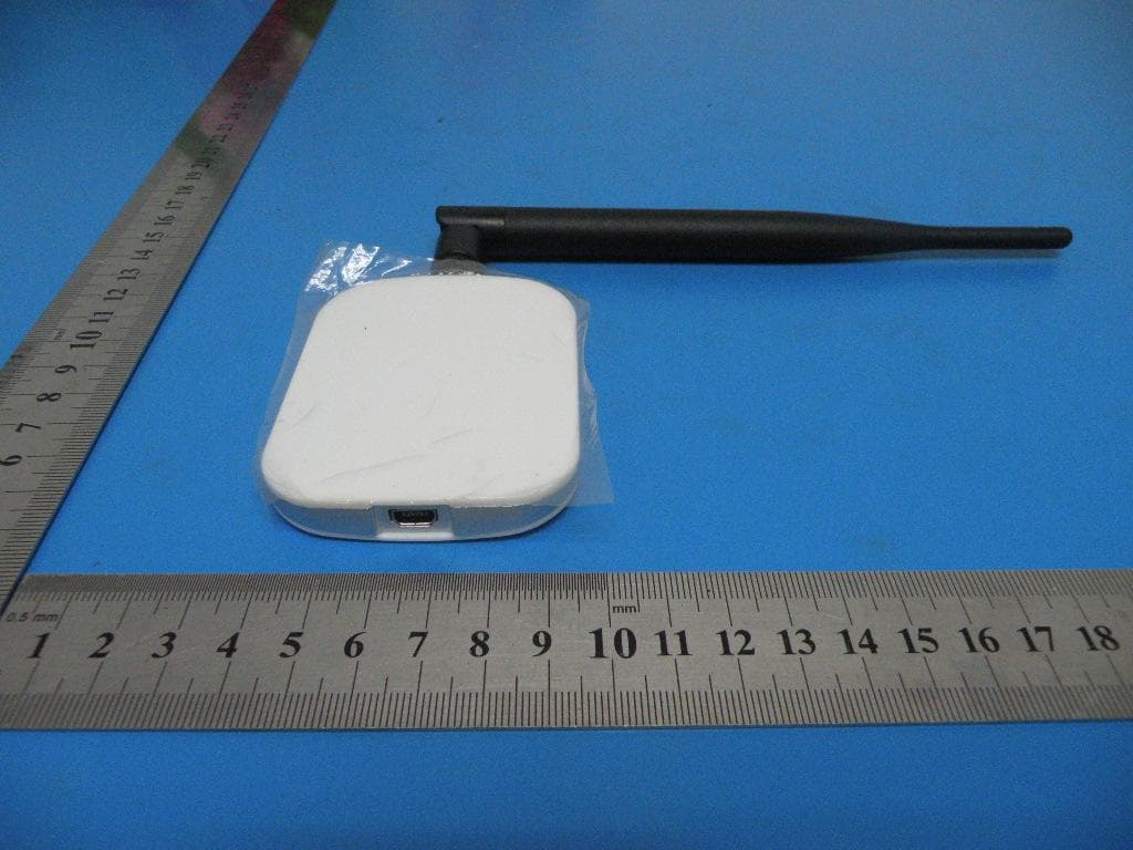
AMBJN7
Aug 01, 2013Wireless USB Adapter
Equipment Class
DTS - Digital Transmission System