ANO20030400LEGIBM 11a/b/g Wireless LAN Mini PCI Adapter
International Business Machines Corporation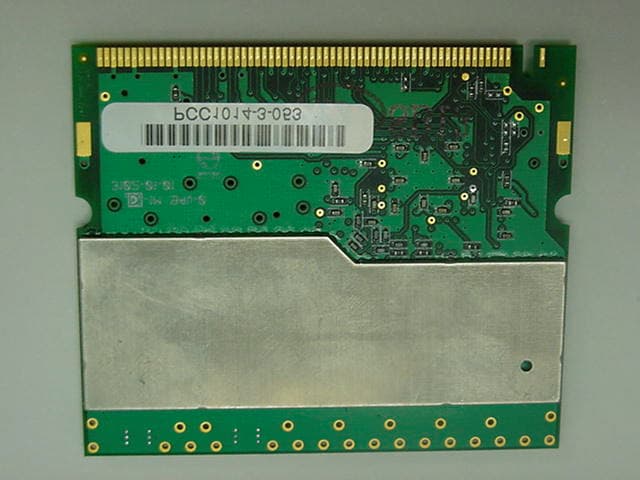
Click to zoom
Application Details
- Equipment Class
- DTS - Digital Transmission System
- Date of Grant
- Jul 02, 2003
- Application Purpose
- Original Equipment
- Date of Application
- Jul 02, 2003
- Equipment Note
- IBM 11a/b/g Wireless LAN Mini PCI Adapter
- Frequency Range
- 5745.00000000 - 5825.00000000
- Country
- United States
Documents & Files
Document Text
Text extracted from the exhibit documents filed with the FCC. Open a document above to read the original.
Users Manual
FCC Test Report FCC ID: ANO20030400LEG Document Number: FCC 19-0224-0 Prepared by T. Murota User’s Manual The attachment is the regulatory notices related to the FCC Part 15C and IC RSS-210 drawn from the user’s manual of the IBM 11a/b/g Wireless LAN Mini PCI Adapter. Please see pages 1 and 24 through 27 for the related portion to the FCC rule concerning the applying LMA transmitter module. Part Number: 31P9715 Product warranty and notices for IBM 11a/b/g Wireless LAN Mini PCI Adapter IBM ® 11a/b/g Wireless LAN Mini PCI Adapter is supported for use with the following IBM ThinkPad ® series: vIBM ThinkPad R40 Series For information concerning series and models announced after the publication of this notice, visit the Web site at www.ibm.iom/pc/qtechinfo/MIGR-43693.html Read first – Regulatory information Note:To use IBM 11a/b/g Wireless LAN Mini PCI Adapter, a special type of BIOS, called “Electronic Handshake,” must be installed on your ThinkPad computer. The “Electronic Handshake” BIOS will function only on the authorized models named above. The IBM 11a/b/g Wireless LAN Mini PCI Adapter complies with the radio frequency and safety standards of any country or region in which it has been approved for wireless use. You are requested to install it and use your ThinkPad computer with this adapter in strict accordance with the instructions as described in “Wireless regulatory notice” on page 24. Read first – Safety information Before installing this product, read the Safety Information. Antes de instalar este produto, leia as Informações de Segurança. Pred instalací tohoto produktu si prectete prírucku bezpecnostních instrukcí. © Copyright IBM Corp. 20031 Læs sikkerhedsforskrifterne, før du installerer dette produkt. Ennen kuin asennat tämän tuotteen, lue turvaohjeet kohdasta Safety Information. Avant d’installer ce produit, lisez les consignes de sécurité. Vor der Installation dieses Produkts die Sicherheitshinweise lesen. Prima di installare questo prodotto, leggere le Informazioni sulla Sicurezza. Lees voordat u dit product installeert eerst de veiligheidsvoorschriften. Les sikkerhetsinformasjonen (Safety Information) før du installerer dette produktet. Antes de instalar este produto, leia as Informações sobre Segurança. Pred inštaláciou tohto zariadenia si pečítaje Bezpečnostné predpisy. Antes de instalar este producto lea la información de seguridad. Lässäkerhetsinformationen innan du installerar den här produkten. 2 Warranty information This section contains the warranty period for your product, information about obtaining warranty service and support, and the IBM Statement of Limited Warranty. Warranty period Contact your place of purchase for warranty service information. Some IBM Machines are eligible for on-site warranty service depending on the country or region where service is performed. Machine -IBM 11a/b/g Wireless LAN Mini PCI Adapter Warranty periodService delivery method Parts - 1 year, labor - 1 yearCustomer carry-in or mail-in For information on European Union legal rights under applicable national legislation governing the sale of consumer goods, go to“European Union warranty information”on page 16. Service and support The following information describes the technical support that is available for your product, during the warranty period or throughout the life of the product. Refer to your IBM Statement of Limited Warranty for a full explanation of IBM warranty terms. Warranty information on the World Wide Web:The IBM Machine Warranties Web site at http://www.ibm.com/servers/support/machine_warranties/ contains a worldwide overview of the IBM Limited Warranty for IBM Machines, a glossary of terms used in the Statement of Limited Warranty, Frequently Asked Questions (FAQ), and links to Product Support Web pages. The IBM Statement of Limited Warranty is available from this Web site in 29 languages in Portable Document Format (PDF). Online technical support:Online technical support is available during the life of your product. Online assistance can be obtained through the Personal Computing Support Web site. Online technical support IBM Personal Computing Support Web Sitehttp://www.ibm.com/pc/support During the warranty period, assistance for replacement or exchange of defective components is available. In addition, if your IBM option is installed 3 in an IBM computer, you might be entitled to service at your location. Your technical support representative can help you determine the best alternative. Telephone technical support:Installation and configuration support through the IBM HelpCenter ® will be withdrawn or made available for a fee, at IBM’s discretion, 90 days after the option has been withdrawn from marketing. Additional support offerings, including step-by-step installation assistance, are available for a nominal fee. To assist the technical support representative, have available as much of the following information as possible: vOption name vOption number vProof of purchase vComputer manufacturer, model, serial number (if IBM), and manual vExact wording of the error message (if any) vDescription of the problem vHardware and software configuration information for your system If possible, be at your computer. Your technical support representative might want to walk you through the problem during the call. For the support telephone number and support hours by country, refer to the following table. If the number for your country or region is not listed, contact your IBM reseller or IBM marketing representative. Response time may vary depending on the number and nature of the calls received. Support 24 hours a day, 7 days a week Canada (Toronto only)416-383-3344 Canada (all other)1-800-565-3344 U.S.A. and Puerto Rico1-800-426-7378 All other countries and regionsGo to http://www.ibm.com/pc/support/, and clickSupport Phone List. 4 IBM Statement of Limited Warranty Z125-4753-06 8/2000 This warranty statement consists of two parts: Part 1 and Part 2. Be sure to read Part 1…
Text truncated - open the document above for the full version.
Attestation Statements
FCC Test Report FCC ID: ANO20030400LEG Document Number: FCC 19-0224-0 Prepared by T. Murota 1/1 Limited Modular Transmitter Approval Qualification 1. The modular transmitter has its own metal shielding covers on both top and back sides, which shield over the RF circuits (VCO, SAW, ..etc.). Refer to the “External Photos” exhibit. 2. The modular transmitter has its own buffered modulation/data inputs. All inputs to the modules are buffered through the logic or microprocessor circuitry. Refer to the “Block Diagram” and “Schematic Diagrams” exhibits. 3. The modular transmitter has its own power supply regulator and local reference oscillator. The device operates from the 3.3V host PC supply. The design includes an on-board voltage converter and regulator for separate digital and analog power supplies. Refer to the “Block Diagram” and “Schematic Diagrams” exhibits. 4. The modular transmitter complies with the antenna requirements of Section 15.203 and 204(c) with an unique electrical antenna connector, so called “Electronic Handshake”. Also the unique connector was authorized by the FCC on December/2002 to meet Section 15.407(d). Please refer to the “Confidential_BIOS_Lock” exhibit. Each antenna system used for the applying module shall be approved(certified) with the module. This application includes the built-in type antennas of IBM laptop computer, ThinkPad R40 Series. 5. The modular transmitter was tested in a stand-alone configuration with each built-in antenna of the host device connected to the proper AC adapter. It complies with the AC power line conducted requirements found in Section 15.207. 6. The modular transmitter is labeled with its own FCC ID number. Also the host device in which the modular transmitter is plugged has a label pointing the FCC ID number location. Please refer to the separate exhibit of the host antenna system, “Antenna Info” exhibit. 7. The modular transmitter complies with the applied specific rule and operating requirements applicable to the transmitter, and the adequate instructions along with the module to be explained for customers are provided with the user’s manual. 8. The modular transmitter complies with the applicable RF exposure requirements. The proper RF exposure evaluations were performed with the host devices in line with the FCC Rules in Sections 2.1091 (MPE), since the antenna separation distance of 20cm or more from human’s body is maintained for the host device.
Cover Letter(s)
FCC Test Report FCC ID: ANO20030400LEG Document Number: FCC 19-0224-0 Yellow Sheet : No. EMA16 Application Document for FCC Part 15, Subpart C (Intentional Radiator) Product Name: IBM 11a/b/g Wireless LAN Mini PCI Adapter Document Number: FCC 19-0224-0 FCC ID: ANO20030400LEG June 02, 2003 EMC R&D Staff Engineer Toshiya Murota Signature: IBM Japan, Ltd. EMC Engineering LAB-S59 1623-14, Shimotsuruma, Yamato-shi Kanagawa-ken 242-8502, Japan Phone: +81-46-215-6574 Fax: +81-46-273-7420 E-Mail: [email protected] Portable Product Development No. 1 Hajime Isoda Signature: IBM Japan, Ltd. Portable Systems LAB-R16 1623-14, Shimotsuruma, Yamato-shi Kanagawa-ken 242-8502, Japan Phone: +81-46-215-2619 EMC Engineering Manager / NVLAP signatory Akihisa Sakurai Signature: IBM Japan, Ltd. EMC Engineering LAB-S59 1623-14, Shimotsuruma, Yamato-shi Kanagawa-ken 242-8502, Japan Phone: +81-46-215-2613 Fax: +81-46-273-7420 E-Mail: [email protected] Portable Systems Director Arimasa Naitoh Signature: IBM Japan, Ltd. Portable Systems LAB-R11 1623-14, Shimotsuruma, Yamato-shi Kanagawa-ken 242-8502, Japan Phone: +81-46-215-6110 FCC Test Report FCC ID: ANO20030400LEG Document Number: FCC 19-0224-0 Prepared by T. Murota 2/3 Outline of Submission 1. Objective This is a Certification Compliance Report for FCC Part 15 subpart C (Intentional Radiator). l The applying equipment: IBM 11a/b/g Wireless LAN Mini PCI Adapter l FCC ID: ANO20030400LEG 2. Product Description The applying modular transmitter device is an OEM mini-PCI wireless LAN card supplied by PHILIPS Components. The modular device complies with the following transmission modes. l IEEE802.11a (5.2GHz band OFDM) l IEEE802.11a (5.8GHz band OFDM) l IEEE802.11b (2.4GHz band Direct Sequence Spread Spectrum) l IEEE802.11g (2.4GHz band OFDM) The 5.2GHz band OFDM mode is subjected to the FCC 15 subpart E (U-NII device), and is to be certified with a separate application as composite device. The transmitter module was previously granted as a complete system (FCC ID: ANO20020300D3L). But the IEEE802.11g transmission mode was excluded at the period, since the driver software for the mode was not implemented for the host PC. The following is the enhancement of this application. l To enable IEEE802.11g (2.4GHz band OFDM) on the specified host (IBM ThinkPad R40 Series) l To employ the “Electronic Handshake” BIOS Loch A slight change was placed on the applying module but the core PCB and RF components are the same as the previous submission, so the RF electrical characteristics of the transmission modes for IEEE802.11a & 11b are not affected by the enhancement. Therefore, the measurement test results for those modes are remained the same as the granted device. Refer to the attached OEM acknowledgement letter issued by the supplier in this exhibit. 3. Installation of the applying transmitter The applying LMA transmitter is a user installable wireless card. The supported host device for the applying LMA transmitter is IBM ThinkPad R40 Series. An unique electrical connector (so called “Electronic Handshake” BIOS Lock) is employed for the host devices to satisfy the FCC Part 15.203 or RSS-210 Ë5.5, and the FCC Part 15.407(d) or RSS 6.2.2 q1(i). This mechanism enables users to install the applying LMA transmitter to the specified host(ThinkPad R40 Series). The detail explanation of the unique coupling between the LMA transmitter and antenna systems is FCC Test Report FCC ID: ANO20030400LEG Document Number: FCC 19-0224-0 Prepared by T. Murota 3/3 shown in the separate exhibit “Confidential_BIOS_Lock”, however IBM would like to hold it in confidence to maintain the secure "unique operability" with the applying card and IBM antenna systems. The BIOS Lock function is also effective for the user’s maintenance in replacing a broken card with a spare part. 4. Collocation with other transmitter The applying LMA transmitter collocates with the following Bluetooth transmitters and transmits simultaneously. - IBM Integrated Bluetooth with 56 Modem(FCC ID: ANO20020100MTN) - Bluetooth UltraPort Module from IBM(FCC ID: PI4BT-ULTRA) - Bluetooth PC Card II(FCC ID: PI4BT-IBM-PCII) As for the RF safety evaluation, refer to the separate “RF Exposure” exhibit. 5. Declaration of Equivalency to granted device The attachment in next page is the declaration of equivalency for the RF electrical characteristics between the applying LMA transmitter and the previous granted device. The subjected devices : FCC ID of IBM product Model number of the OEM supplier (PHILIPS Components) Granted deviceANO20020300D3LPH11107-X The applying deviceANO20030400LEGPH12127-X Accton & Philips Wireless Networking WCM-HO-PD-042 PH11107-X / PH12127-X Issue 1 Declaration Of Equivalency 29 th May 2003 Page 1 of 4 Author(s): A.D.McPherson Date: 29 th May 2003 ACCTON & PHILIPS Wireless Networking 1962 Zanker Road San Jose Ca 95112 United States of America TECHNICAL REPORT 802.11 Combo MiniPCI WLAN Card Model No: PH11107-X / PH12127-X Declaration Of Equivalency Accton & Philips Wireless Networking WCM-HO-PD-042 PH11107-X / PH12127-X Issue 1 Declaration Of Equivalency 29 th May 2003 Page 2 of 4 CHANGE HISTORY Revision By Whom Comment Date Issue 1 D McPherson Initial Preparation. May 29t h , 2003 CONTENTS 1 Preface..................................................................................................................................................3 1.1 Purpose...........................................................................................................................................3 1.2 Scope..............................................................................................................................................3 1.3 Audience..........................................................................................................................................3 1.4 Abbreviations & Definitions................................................................................................…
Text truncated - open the document above for the full version.
Cover Letter(s)
FCC Test Report FCC ID: ANO20030400LEG Document Number: FCC 19-0224-0 IBM Japan Ltd. 1623-14, Shimotsuruma, Yamato Kanagawa 242-8502, Japan June 2, 2003 PCTEST Engineering Laboratory, Inc. 6660-B Dobbin Road Columbia, MD 21045 Subject: Request for FCC Certification of Part 15, Subpart C (Composite application with Subpart E) Dear sir / madam : Please find enclosed an IBM’s application document for the FCC Part 15, Subpart C certification. - FCC ID : ANO20030400LEG - Applying equipment name: IBM 11a/b/g Wireless LAN Mini PCI Adapter - Device type: LMA device of 2412-2462MHz Direct Sequence and 5745-5825MHz OFDM combo DTS system The applying product is a IEEE802.11a/b/g WLAN mini-PCI adapter and is an user installable LMA transmitter module plugged into the specific host PCs (IBM ThinkPad R40 Series). The “Electronic Handshake” unique connector is employed for user installation. If any further information is required concerning this application, please contact us. Sincerely, Akihisa Sakurai Manager, EMC Engineering Yamato Laboratory, IBM Japan Ltd.
Cover Letter(s)
FCC Test Report FCC ID: ANO20030400LEG Document Number: FCC 19-0224-0 IBM Japan Ltd. 1623-14, Shimotsuruma, Yamato Kanagawa 242-8502, Japan June 02, 2003 PCTEST Engineering Laboratory, Inc. 6660-B Dobbin Road Columbia, MD 21045 Subject: Confidentiality Request for FCC Certification of Part 15, Subpart C Dear sir : Please find enclosed an IBM’s application for the FCC Part 15, Subpart C certification : - FCC ID : ANO20030400LEG - Applying equipment name: IBM 11a/b/g Wireless LAN Mini PCI Adapter - Device type: 2412M-2462MHz Direct Sequence & 5745M-5825MHz OFDM combo DTS device Pursuant to 47 CFR section 0.457(d) and 0.459, we hereby request confidentiality for the schematics, detailed block diagrams, detailed theories of operation, and parts list. The subjected files are as follows. - Confidential_Schematic_Diagrams.pdf - Confidential_Block_Diagrams.pdf - Confidential_Circuitry_Description_UNII.pdf - Confidential_Parts_List.pdf - Confidential_BIOS_Lock.pdf (Electronic Handshake logic) Sincerely, Akihisa Sakurai Manager, EMC Engineering Yamato Laboratory, IBM Japan Ltd.
Cover Letter(s)
FCC ID: ANO20030400LEG Document Number: FCC 19-0224-1 Prepared by T. Murota. 1/1 IBM Japan Ltd. 1623-14, Shimotsuruma, Yamato-shi Kanagawa-ken 242-8502, Japan To whom this may concern June 25, 2003 OET Requested Information FCC ID : ANO20030400LEG Applicant : International Business Machines Corporation Correspondence Reference Number: 230625A.ANO Confirmation Number: TC3145 Original Requested Date : June 25, 2003 Subject 1) Page 1/5 of the RF Exposure Evaluation exhibit has incorrect output power (mW). Please correct accordingly. Answer 1) The subjected exhibit is revised with the correct output power values. Please find a separate exhibit “RF_Exposure_DTS_up.pdf. Sincerely, June 25, 2003 Toshiya Murota, Staff Engineer, EMC R&D Engineering, Yamato Laboratory, IBM Japan Ltd.
External Photos
FCC Test Report FCC ID: ANO20030400LEG Document Number: FCC 19-0224-0 Prepared by T. Murota 1/1 External Photos Back side(with shielding) Top side (with shielding) Auxiliary Antenna Port Main Antenna Port Antenna Terminals
ID Label/Location Info
FCC Test Report FCC ID: ANO20030400LEG Document Number: FCC 19-0224-0 Prepared by T. Murota 1/1 Product Labeling Top side
Internal Photos
FCC Test Report FCC ID: ANO20030400LEG Document Number: FCC 19-0224-0 Prepared by T. Murota 1/1 Internal Photos Back side (without shielding) Top side (without shielding) Antenna Terminals
Operational Description
FCC Test Report, FCC ID: ANO20030400LEG Document Number: FCC-19-0224-0 Prepared by T. Murota 1/10 Host Unit Antenna Information for ThinkPad R40 Series 1.HOST PC INFORMATION.................................................................................................................2 2.HOST PC LABELING.........................................................................................................................4 3.ANTENNA SPECIFICATIONS...........................................................................................................6 3.1TRANSMISSION ANTENNA ASSEMBLY OVERVIEW.....................................................................................6 3.2ANTENNA PHOTOS................................................................................................................................7 FCC Test Report, FCC ID: ANO20030400LEG Document Number: FCC-19-0224-0 Prepared by T. Murota 2/10 1.Host PC Information The two inverted F-figure type antennas are built in the left and right side of LCD. Those diversity antennas are not used simultaneously. One of the antennas is selected automatically or manually to have a good quality of radio communication. The selected antenna performs transmission or receiving in half duplex alternatively. Auxiliary Antenna Main Antenna Mini-PCI slot and Wireless card FCC ID and IC certification number are visible when the slot cover is removed. FCC Test Report, FCC ID: ANO20030400LEG Document Number: FCC-19-0224-0 Prepared by T. Murota 3/10 IBM ThinkPad R40 Series supports threes size of LCD. LCD 15 inch Model LCD 14 inch Model LCD 13 inch Model FCC Test Report, FCC ID: ANO20030400LEG Document Number: FCC-19-0224-0 Prepared by T. Murota 4/10 2.Host PC Labeling Bottom view, Front side FCC Test Report, FCC ID: ANO20030400LEG Document Number: FCC-19-0224-0 Prepared by T. Murota 5/10 Label for a different model of the applying equipment (ThinkPad R40 Series) The host device (ThinkPad R40 Series) supports the applying transmitter and a built-in type Bluetooth LMA which is to be certified separately with FCC ID: ANO20020100MTN. FCC ID of a separate application granted on Jan/21/2003 ( not user installable ) FCC Test Report, FCC ID: ANO20030400LEG Document Number: FCC-19-0224-0 Prepared by T. Murota 6/10 3.Antenna Specifications 3.1 Transmission Antenna assembly overview IBM ThinkPad R40 Series DesignatorManufactureAntenna type Cable type and length Gain (dBi) Note 1) 2.4GHz band 0.46 dBi (peak) 3301BZ9078A 15 inch LCD model Main antenna Hitachi Cable Ltd. (Japan) Dual Band Inverted F type Antenna coax 530mm 5.8GHz band -0.49 dBi (peak) 2.4GHz band -1.06 dBi (peak) 3301BZ9079A 15 inch LCD model Auxiliary antenna Hitachi Cable Ltd. (Japan) Dual Band Inverted F type Antenna coax 640mm 5.8GHz band -0.12 dBi (peak) 2.4GHz band -0.37 dBi (peak) 3301BZ9076A 13/14 inch LCD model Main antenna Hitachi Cable Ltd. (Japan) Dual Band Inverted F type Antenna coax 530mm 5.8GHz band 0.85 dBi (peak) 2.4GHz band 0.83 dBi (peak) 3301BZ9077A 13/14 inch LCD model Auxiliary antenna Hitachi Cable Ltd. (Japan) Dual Band Inverted F type Antenna coax 640mm 5.8GHz band -0.94 dBi (peak) Note 1): 1a. Includes all cable losses. 1b. Antenna type should be Omni Directional and have gain of 3.0 dBi or less for IEEE802.11a(5GHz band) and have gain of 2.0 dBi or less for IEEE802.11b & g(2.4GHz band), regarding the IBM internal specification. FCC Test Report, FCC ID: ANO20030400LEG Document Number: FCC-19-0224-0 Prepared by T. Murota 7/10 3.2 Antenna Photos R40: LCD 15 inch Model, Antenna locations Auxiliary antenna Inverted-F type P/N: 3301BZ9079A Main antenna Inverted-F type P/N: 3301BZ9078A FCC Test Report, FCC ID: ANO20030400LEG Document Number: FCC-19-0224-0 Prepared by T. Murota 8/10 R40: LCD 13/14 inch Model, Antenna locations Auxiliary antenna Inverted-F type P/N: 3301BZ9077A Main antenna Inverted-F type P/N: 3301BZ9076A FCC Test Report, FCC ID: ANO20030400LEG Document Number: FCC-19-0224-0 Prepared by T. Murota 9/10 R40: LCD 13/14 inch Model, Antenna Exterior Photos Main Antenna (Left) Manufacturer: Hitachi Cable Ltd. Parts number: 3301BZ9076A Inverted-F type antenna Cable : coax 530 mm Auxiliary Antenna (Right) Manufacturer: Hitachi Cable Ltd. Parts number: 3301BZ9077A Inverted-F type antenna Cable : coax 640 mm FCC Test Report, FCC ID: ANO20030400LEG Document Number: FCC-19-0224-0 Prepared by T. Murota 10/10 R40: LCD 13/14 inch Model, Antenna Exterior Photos Main Antenna (Left) Manufacturer: Hitachi Cable Ltd. Parts number: 3301BZ9078A Inverted-F type antenna Cable : coax 530 mm Auxiliary Antenna (Right) Manufacturer: Hitachi Cable Ltd. Parts number: 3301BZ9079A Inverted-F type antenna Cable : coax 640 mm
RF Exposure Info
FCC Test Report FCC ID: ANO20030400LEG Document Number: FCC 19-0224-0 Prepared by T. Murota 1/5 RF Exposure evaluation 1. RF Exposure evaluation for the applying transmitter As shown in the following photo, both main and auxiliary WLAN antennas of the applying laptop PC, IBM ThinkPad R40 Series, are located at the top of display (LCD) bezel. The separation distances between the antennas and the human body are 20cm or more. Therefore the laptop PC can be categorized as a mobile device by FCC CFR 47 Section 2.1091. [MPE evaluation] The following table shows the highest conducted peak output power values measured for each transmission mode and the maximum peak antenna gains of the applying modular device. Transmission mode P: conducted peak output power Test report number G: peak antenna gain 2.4GHz band DSSS 17.3dBm (51.3mW)FCC 19-0224-0+ 0.83 dBi 2.4GHz band OFDM 17.4dBm (49.0mW)FCC 19-0237-0+ 0.83 dBi 5.8GHz bnad OFDM 16.7dBm (55.0mW)FCC 19-0224-0+ 0.85 dBi With those results, the maximum power density at 20cm distance is calculated as follows. Antennas are located at the same height The separation distance between the antenna and the human body (lap) is about 22cm . FCC Test Report FCC ID: ANO20030400LEG Document Number: FCC 19-0224-0 Prepared by T. Murota 2/5 Transmission mode EIRP = P + G (dBm) EIRP (mW) Max. power density S = EIRP/(4 % 20 2 % o) 2.4GHz band DSSS 18.1365.00.0129 mW/ cm 2 2.4GHz band OFDM 18.2365.50.0130 mW/ cm 2 5.8GHz bnad OFDM 17.657.40.0114 mW/ cm 2 Since the applying modular transmitter device does not function to emit the radio frequency from both diversity antennas simultaneously, the above results are the maximum values of RF exposure to the persons, and are far below the MPE limit (1.0 mW/ cm 2 ). Therefore the LMA transmitter meets the MPE requirements for general Population/Uncontrolled exposure. FCC Test Report FCC ID: ANO20030400LEG Document Number: FCC 19-0224-0 Prepared by T. Murota 3/5 2. RF Exposure evaluation for co-located Bluetooth transmitters The applying laptop PC (ThinkPad R40 Series) supports three kinds of Bluetooth devices as follows. FCC ID Grantee Name Product Name Granted Date ERP in FCC test report PI4BT-ULTRA Bluetooth Ultraport Module May/22/20011.4 mW User’s option PI4BT-IBM-PCII TDK Systems Europe Ltd. Blutooth PC Card II August/21/2001 1.0mW Built-in type LMA transmitter ANO20020100MTNIBM Japan, Ltd. IBM integrated Blutooth with 56K Modem February/26/2003 2.5mW Interfaces to connect Wireless options Bluetooth Built_in antenna FCC Test Report FCC ID: ANO20030400LEG Document Number: FCC 19-0224-0 Prepared by T. Murota 4/5 The main and auxiliary antennas placed at LCD section of the host device (ThinkPad R40 Series) are assembled apart from each Bluetooth antenna shown in the previous page with 20 cm or more. Therefore the RF exposure evaluation for those Bluetooth transmitters is allowed to be examined independently of the applying WLAN antennas. In other word, the SAR testing for the applying transmitter in co-locating with those Bluetooth options is not required thanks to the following reasons. When a customer operates the applying PC on one’s lap, the sufficient separation distance (minimum 20cm) between the above Bluetooth antennas and the person’s body (lap) can not be maintained. But the footnote of the Section 3 in Supplement C to OET Bulletin 65 states “ 14 .......... If a device, its antenna or other radiating structures are operating at closer than 2.5 cm from a person’s body or in contact with the body, SAR evaluation may be necessary when the output is more than 50 – 100 mW, depending on the device operating configurations and exposure conditions.” The total output power of the three Bluetooth transmitters in the previous table does not exceed 5mW. Therefore these transmitters also satisfy the RF exposure evaluation regarding CFR 47 Part 15.247(b)(4) without a SAR compliance test report, and can operate with the applying transmitter simultaneously. IBM Web site guides to customers about the grant condition concerning those collaborating transmitter devices. See the next page. FCC Test Report FCC ID: ANO20030400LEG Document Number: FCC 19-0224-0 Prepared by T. Murota 5/5 4. IBM Web site for user’s guidance concerning the co-located transmitters Note) The info for the applying LMA transmitter is not available until the product announcement. http://www.pc.ibm.com/qtechinfo/MIGR-43693.html
RF Exposure Info
FCC Test Report FCC ID: ANO20030400LEG Document Number: FCC 19-0224-0 Prepared by T. Murota 1/5 RF Exposure evaluation 1. RF Exposure evaluation for the applying transmitter As shown in the following photo, both main and auxiliary WLAN antennas of the applying laptop PC, IBM ThinkPad R40 Series, are located at the top of display (LCD) bezel. The separation distances between the antennas and the human body are 20cm or more. Therefore the laptop PC can be categorized as a mobile device by FCC CFR 47 Section 2.1091. [MPE evaluation] The following table shows the highest conducted peak output power values measured for each transmission mode and the maximum peak antenna gains of the applying modular device. Transmission mode P: conducted peak output power Test report number G: peak antenna gain 2.4GHz band DSSS 17.3dBm (53.8mW)FCC 19-0224-0+ 0.83 dBi 2.4GHz band OFDM 17.4dBm (55.0mW)FCC 19-0237-0+ 0.83 dBi 5.8GHz bnad OFDM 16.7dBm (46.8mW)FCC 19-0224-0+ 0.85 dBi With those results, the maximum power density at 20cm distance is calculated as follows. Antennas are located at the same height The separation distance between the antenna and the human body (lap) is about 22cm . FCC Test Report FCC ID: ANO20030400LEG Document Number: FCC 19-0224-0 Prepared by T. Murota 2/5 Transmission mode EIRP = P + G (dBm) EIRP (mW) Max. power density S = EIRP/(4 % 20 2 % o) 2.4GHz band DSSS 18.1365.020.0130 mW/ cm 2 2.4GHz band OFDM 18.2366.530.0133 mW/ cm 2 5.8GHz bnad OFDM 17.5556.890.0114 mW/ cm 2 Since the applying modular transmitter device does not function to emit the radio frequency from both diversity antennas simultaneously, the above results are the maximum values of RF exposure to the persons, and are far below the MPE limit (1.0 mW/ cm 2 ). Therefore the LMA transmitter meets the MPE requirements for general Population/Uncontrolled exposure. FCC Test Report FCC ID: ANO20030400LEG Document Number: FCC 19-0224-0 Prepared by T. Murota 3/5 2. RF Exposure evaluation for co-located Bluetooth transmitters The applying laptop PC (ThinkPad R40 Series) supports three kinds of Bluetooth devices as follows. FCC ID Grantee Name Product Name Granted Date ERP in FCC test report PI4BT-ULTRA Bluetooth Ultraport Module May/22/20011.4 mW User’s option PI4BT-IBM-PCII TDK Systems Europe Ltd. Blutooth PC Card II August/21/2001 1.0mW Built-in type LMA transmitter ANO20020100MTNIBM Japan, Ltd. IBM integrated Blutooth with 56K Modem February/26/2003 2.5mW Interfaces to connect Wireless options Bluetooth Built_in antenna FCC Test Report FCC ID: ANO20030400LEG Document Number: FCC 19-0224-0 Prepared by T. Murota 4/5 The main and auxiliary antennas placed at LCD section of the host device (ThinkPad R40 Series) are assembled apart from each Bluetooth antenna shown in the previous page with 20 cm or more. Therefore the RF exposure evaluation for those Bluetooth transmitters is allowed to be examined independently of the appl…
Text truncated - open the document above for the full version.
Contact Information
Applicant
John Maas(Corp Program Manager EMC)
Technical Contact
PCTEST Engineering Lab., Inc.Randy Ortanez
[email protected]410-290-6652
6660-B Dobbin Road · Columbia, Maryland · United States
Test Firm
IBM JapanAkihisa Sakurai
Technical Specifications
| # | Rule Parts | Frequency Range | Power Output |
|---|---|---|---|
| 2 | 15C | 5.75 GHz - 5.83 GHz | 46.90 mW |
Other Applications from International Business Machines Corporation

ANO-7054SC
Jun 30, 2005Bluetooth Enabled Handheld Scanner
Equipment Class
DSS - Part 15 Spread Spectrum Transmitter
ANO-7054
Jun 28, 2005Model 7054 Mobile Tablet
Equipment Class
DTS - Digital Transmission System
ANOX41T
May 02, 2005ThinkPad X41 Tablet Series
Equipment Class
DCD - Part 15 Low Power Transmitter Below 1705 kHz
ANO20040700HER
Dec 08, 2004Model: J07M067 Bluetooth Standard Class 2 Adapter
Equipment Class
DSS - Part 15 Spread Spectrum Transmitter
ANO20040601CX2
Oct 06, 2004Model: WM3B2915ABG (802.11a/b/g WLAN Adapter)
Equipment Class
DTS - Digital Transmission System