ANO20030500CMRModel: T60H786-U (802.11 b/g Wireless LAN Adapter)
International Business Machines Corporation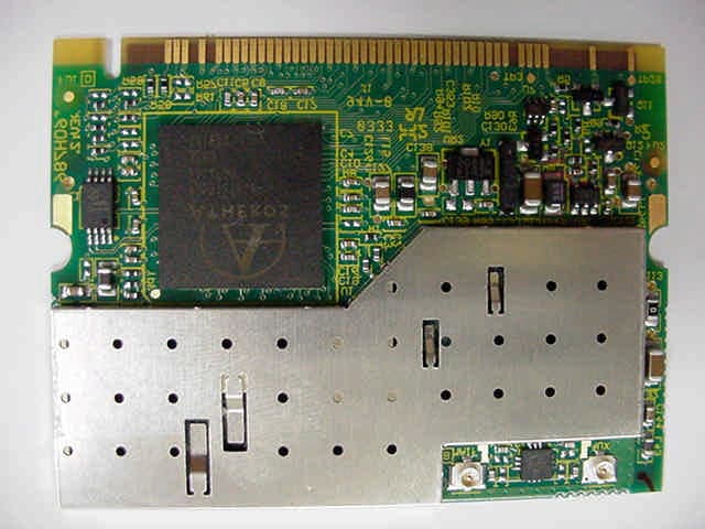
Click to zoom
Application Details
- Equipment Class
- DTS - Digital Transmission System
- Date of Grant
- Dec 18, 2003
- Application Purpose
- Original Equipment
- Date of Application
- Dec 18, 2003
- Equipment Note
- Model: T60H786-U (802.11 b/g Wireless LAN Adapter)
- Frequency Range
- 2412.00000000 - 2462.00000000
- Country
- United States
Documents & Files
Document Text
Text extracted from the exhibit documents filed with the FCC. Open a document above to read the original.
Users Manual
FCC Test Report FCC ID: ANO20030500CMR Document Number: FCC 19-0253-0 Prepared by T. Murota User’s Manual (for ThinkPad X30 and X40 Series) The attachment is the part of the user’s manual of the specific host devices (IBM ThinkPad X30 and X40 Series) that indicates the regulatory notices concerning the FCC Part 15 and IC RSS- 210/102. Due to the large volume, the notices for other countries and other regulatory issues (e.g. Telecommunications, Safety, and EMC ) are omitted. Part Number: 13N6017 Regulatory Notice for ThinkPad ® X40 Series This notice is a supplementary document of the ThinkPad X40 Series Service and Troubleshooting Guide. Please read this document before you use the ThinkPad X40 Series computer. The ThinkPad X40 Series computer complies with the radio frequency and safety standards of any country or region in which it has been approved for wireless use. Yo u must install and use your ThinkPad computer in strict accordance with the instructions as described hereafter. Réglementation concernant les ordinateurs ThinkPad X40 Series Le présent document complète le manuel ThinkPad X40 Series - Guide de maintenance et d’identification des incidents. L’ordinateur ThinkPad X40 Series est conforme aux normes de radiofréquence et de sécurité en vigueur dans les pays ou régions o son utilisation sans fil a été acceptée. L’ordinateur doit être installé et utilisé conformément aux instructions fournies ci-après. Avant d’utiliser votre ordinateur ThinkPad X40, veuillez lire ce document. Hinweis zu Einheiten für denThinkPad X40 Series Dieser Hinweis ergänzt die Informationen im Handbuch ThinkPad X40 - Service und Fehlerbehebung. Der ThinkPad X40 erfüllt die Funkfrequenz- und Sicherheitsstandards der Länder und Regionen, in denen er für die Verwendung als drahtlose Einheit zugelassen ist. Der ThinkPad X40 muss exakt wie nachfolgend beschrieben installiert und verwendet werden. Lesen Sie unbedingt die entsprechenden Informationen in diesem Dokument, bevor Sie den ThinkPad X40 verwenden. © Copyright IBM Corp. 2003 1 USA — Federal Communications Commission (FCC) This device complies with part 15 of the FCC Rules. Operation is subject to the following two conditions: 1. This device may not cause harmful interference, and 2. this device must accept any interference received, including interference that may cause undesired operation. User installable wireless modules v Mini-PCI Cards - FCC ID: ANO20020201CLK, Model: WM3B2100 (Intel ® PRO/Wireless LAN 2100 3B Mini PCI Adapter) - FCC ID: ANO20030400LEG, Model: PH12127E (IBM 11a/b/g Wireless LAN Mini PCI Adapter) - FCC ID: ANO20030500CMR, Model: T60H786-U (IBM 11b/g Wireless LAN Mini PCI Adapter) v Communication Daughter Card (CDC) - FCC ID: ANO20020100MTN, Model: BMDC200 (IBM Integrated Bluetooth III with 56K Modem) For information concerning the wireless cards announced after the publication of this notice, visit the We b site at www.ibm.com/pc/qtechinfo/MIGR-43693.html IBM 11b/g Wireless LAN Mini PCI Adapter marketed in US and Canada does not support nor function in the extended channels (12ch, 13ch). i) FCC ID of wireless modules There is no FCC ID for Mini-PCI Cards shown on the enclosure of your ThinkPad computer. Instead you will find an indicator pointing to the location of the FCC ID on the bottom side of your ThinkPad computer as shown below in the figure i-1). Also the location of the FCC ID’s indicator for CDC is shown by the figure i-2). The FCC IDs are affixed on each approved module installed in the Mini-PCI Card slot or the CDC slot. 6 i-1) Mini-PCI Cards: v FCC ID: ANO20020201CLK, Model: WM3B2100 (Intel ® PRO/Wireless LAN 2100 3B Mini PCI Adapter), v FCC ID: ANO20030400LEG, Model: PH12127E (IBM 11a/b/g Wireless LAN Mini PCI Adapter), or v FCC ID: ANO20030500CMR, Model: T60H786-U (IBM 11b/g Wireless LAN Mini PCI Adapter) TX FCC ID for an installed transmitter card located under this Customer Access Panel 7 i-2) CDC (FCC ID: ANO20020100MTN, Model: BMDC200 (IBM Integrated Bluetooth III with 56K Modem)) TX FCC ID for an installed CDC transmitter card located under this Customer Access Panel ii) Installation of approved wireless modules If no integrated wireless LAN Mini-PCI Card or RF CDC module is preinstalled in your ThinkPad computer, you can install one, provided by IBM as an option. Plug the wireless card option into the Mini-PCI Card slot or CDC slot located under the expansion slot cover of your ThinkPad computer as shown below. 8 Communication Daughter Card slot Expansion slot cover Mini PCI Card slot Attention: The ThinkPad X40 Series computer contains an authentication mechanism If you install an unauthorized wireless LAN Mini-PCI Card or RF CDC module that is not approved for use in the ThinkPad X40 Series computer, the computer will not start, but only displays an error message and emits beeps. 9 iii) The FCC RF safety requirement The radiated output power of the Wireless LAN Mini-PCI Cards or RF CDC module authorized to use for the ThinkPad X40 Series computer is far below the FCC radio frequency exposure limits. Nevertheless, the ThinkPad X40 Series computer shall be used in such a manner that the potential for human contact during normal operation is minimized as follows: Caution: To comply with FCC RF exposure compliance requirements, a separation distance of at least 20 cm (8 inches) must be maintained between the antenna for the integrated Wireless LAN Mini-PCI Card built in to the screen section and all persons. You are not allowed to disable “standby mode” for the power management function, if you cannot maintain the sufficient antenna separation (at least 20 cm) in any case the LCD is left opened or closed. FCC ID: ANO20020201CLK, Model: WM3B2100 (Intel ® PRO/Wireless LAN 2100 3B Mini PCI Adapter) 20cm Transmitter antenna position 10 FCC ID: ANO20030400LEG, Model: PH12127E (IBM 11a/b/g Wireless LAN Mini PCI Adapter) or FCC ID: ANO20030500CMR, Model: T60H786-U (IBM 11b/g Wireless LAN Mini PCI Adapter) 20cm 20cm Mai…
Text truncated - open the document above for the full version.
Attestation Statements
FCC Test Report FCC ID: ANO20030500CMR Document Number: FCC 19-0253-0 Prepared by T. Murota 1/1 Limited Modular Transmitter Approval Qualification 1. The modular transmitter has its own metal shielding covers on top side, which shields over the RF circuits (oscillator, synthesizer, PA, ..etc.). Refer to the “External Photos” exhibit. 2. The modular transmitter has its own buffered modulation/data inputs. All inputs to the modules are buffered through the logic or microprocessor(AR5213) circuitry. Refer to the “Block Diagram” or “Schematic Diagrams” exhibits. 3. The modular transmitter has its own power supply regulator and local reference oscillator. The device operates from the 3.3V host PC supply. Refer to the “Block Diagram” or “Schematic Diagrams” exhibits. 4. The modular transmitter complies with the antenna requirements of Section 15.203 and 204(c) with an unique electrical antenna connector, so called “BIOS Lock”. Refer to the “Confidential_BIOS_Lock” exhibit. Each antenna system used for the applying module shall be approved(certified) with the module before each product’s announcement date. This application includes the built-in type antennas of IBM laptop computer, ThinkPad X30 Series and X40 Series. 5. The modular transmitter was tested in a stand-alone configuration with each built-in antenna of the host device that was connected to the proper AC adapter. It complies with the AC power line conducted requirements found in Section 15.207. 6. The modular transmitter is labeled with its own FCC ID number. Also the host device in which the modular transmitter is plugged has a label pointing the FCC ID number location. Please refer to the separate exhibit of the host antenna system, “Antenna_Info.pdf” exhibit. 7. The modular transmitter complies with the applied specific rule and operating requirements applicable to the transmitter, and the adequate instructions along with the module to be explained for customers are provided with the user’s manual. 8. The modular transmitter complies with the applicable RF exposure requirements. The proper RF exposure evaluations were performed with the host devices in line with the FCC Rules in Sections 2.1091 (MPE), since the antenna separation distance of 20cm or more from human’s body is maintained for the host device.
Cover Letter(s)
FCC Test Report FCC ID: ANO20030500CMR Document Number: FCC 19-0253-0 Prepared by T. Murota 2/2 Outline of Submission 1. Objective This is a Certification Compliance Report for FCC Part 15 subpart C (Intentional Radiator). l FCC ID: ANO20030500CMR l Model Number: T60H786-U l Advertising Name: IBM 11b/g Wireless LAN Mini PCI Adapter 2. Product Description The applying modular transmitter device is an OEM mini-PCI wireless LAN card supplied by AMBIT Microsystems Corporation. The modular device complies with the following transmission modes. l IEEE802.11b (2.4GHz band DSSS) l IEEE802.11g (2.4GHz band OFDM) 3. Installation of the applying transmitter The applying LMA transmitter is a user installable wireless card. The supported host units for the device are IBM laptop PC ThinkPad X30 Series, and X40 Series. An electrical unique connector (so called “BIOS Lock”) is employed for the host devices to satisfy the FCC Part 15.203 or RSS-210 Ë5.5. This mechanism enables users to install the applying LMA transmitter to the specified host (ThinkPad X30 and X40 Series). The detail explanation of the unique coupling between the LMA transmitter and antenna systems is shown in the separate exhibit “Confidential_BIOS_Lock”, however IBM would like to hold it in confidence to maintain the secure "unique operability" with the applying card and IBM antenna systems. The BIOS Lock function is also effective for the user’s maintenance in replacing a broken card with a spare part. 4. Co-located Transmitters The applying LMA transmitter collocates with the following Bluetooth modules and transmits simultaneously. - FCC ID: ANO20020100MTN (IBM Integrated Bluetooth III with 56 Modem) - FCC ID: PI4BT-ULTRA (Bluetooth UltraPort Module from IBM) - FCC ID: PI4BT-IBM-PCII (Bluetooth PC Card II) As for the RF safety evaluation, refer to the separate exhibit “RF_Exposure.pdf ”.
External Photos
FCC Test Report FCC ID: ANO20030500CMR Document Number: FCC 19-0253-0 Prepared by T. Murota 1/1 External Photos Top side (with shielding) Auxiliary Antenna terminal Main Antenna terminal Back side
ID Label/Location Info
FCC Test Report FCC ID: ANO20030500CMR Document Number: FCC 19-0253-0 Prepared by T. Murota 1/1 Product Labeling Top side FCC ID Model Number
Internal Photos
FCC Test Report FCC ID: ANO20030500CMR Document Number: FCC 19-0253-0 Prepared by T. Murota 1/1 Internal Photos Top side (without shielding) Auxiliary Antenna terminal Main Antenna terminal Back side (No shielding is assembled.)
Operational Description
FCC Test Report FCC ID: ANO20030500CMR Document Number: FCC 19-0253-0 Prepared by T. Murota 1/16 Host Unit Antenna Information 1.Antenna Info of ThinkPad X30 Series..........................................................................................2 1.1Host PC Information.........................................................................................................................2 1.2Host PC Labeling..............................................................................................................................4 1.3Antenna Specifications....................................................................................................................6 1.3.1Transmission Antenna assembly overview.................................................................................6 1.3.2Antenna Locations.......................................................................................................................7 1.3.3Exterior Photos of Antennas........................................................................................................8 2.Antenna Info of ThinkPad X40 Series..........................................................................................9 2.1Host PC Information.........................................................................................................................9 2.2Host PC Labeling............................................................................................................................11 2.3Antenna Specifications..................................................................................................................13 2.3.1Transmission Antenna assembly overview...............................................................................13 2.3.2Antenna Locations.....................................................................................................................14 2.3.3Exterior Photos of Antennas......................................................................................................15 FCC Test Report FCC ID: ANO20030500CMR Document Number: FCC 19-0253-0 Prepared by T. Murota 2/16 1. Antenna Info of ThinkPad X30 Series 1.1Host PC Information The two inverted F-figure type antennas are built in the left and right top sides of LCD as shown in the Photo. Those diversity antennas are not used simultaneously. One of the antennas is selected automatically or manually to have a good quality of radio communication. The selected antenna performs transmission or receiving in half duplex alternatively. Main Antenna Auxiliary Antenna The FCC ID and IC’s Certification Number are visible when the keyboard assembly is removed. FCC Test Report FCC ID: ANO20030500CMR Document Number: FCC 19-0253-0 Prepared by T. Murota 3/16 IBM ThinkPad X30 Series Side View Rear View FCC Test Report FCC ID: ANO20030500CMR Document Number: FCC 19-0253-0 Prepared by T. Murota 4/16 1.2Host PC Labeling Bottom view Front Side Applying LMA transmitter is installed under this location. See page 2. FCC Test Report FCC ID: ANO20030500CMR Document Number: FCC 19-0253-0 Prepared by T. Murota 5/16 Label for a different model of the host PC (ThinkPad X30 Series) The model (X30) supports the applying transmitter and a built-in type Bluetooth LMA module which was granted separately as the FCC ID: ANO20020100MTN on Feb/26/2003 (Class II). Bottom view Front Side The collocated user installable Bluetooth LMA transmitter is installed under this label. (Granted on Feb 26, 2003) FCC Test Report FCC ID: ANO20030500CMR Document Number: FCC 19-0253-0 Prepared by T. Murota 6/16 1.3Antenna Specifications 1.3.1Transmission Antenna assembly overview IBM ThinkPad X30 Series DesignatorManufactureAntenna type Cable type and length Gain (dBi) Note 1) 08K4083 Main antenna Nissei Electric Ltd. (Japan) Dual Band Inverted F type Antenna coax 394mm 2.4GHz band 0.62 dBi (peak) 08K4084 Auxiliary antenna Nissei Electric Ltd. (Japan) Dual Band Inverted F type Antenna coax 534mm 2.4GHz band 1.28 dBi (peak) Note 1): 1a. Includes all cable losses. 1b. Antenna type should be Omni Directional and have gain of 2.0 dBi or less for IEEE802.11b & g (2.4GHz band) regarding the IBM internal specification. FCC Test Report FCC ID: ANO20030500CMR Document Number: FCC 19-0253-0 Prepared by T. Murota 7/16 1.3.2Antenna Locations Auxiliary antenna Dual Band Inverted-F type P/N: 08K4084 Main antenna Dual Band Inverted-F type P/N: 08K4083 FCC Test Report FCC ID: ANO20030500CMR Document Number: FCC 19-0253-0 Prepared by T. Murota 8/16 1.3.3Exterior Photos of Antennas Main Antenna (Left) Manufacturer: Nissei Electric Ltd. Parts Number: 08K4083 Dual Band Inverted-F type antenna Cable : coax 394 mm Auxiliary Antenna (Right) Manufacturer: Nissei Electric Ltd. Parts Number: 08K4084 Dual Band Inverted-F type antenna Cable : coax 534 mm FCC Test Report FCC ID: ANO20030500CMR Document Number: FCC 19-0253-0 Prepared by T. Murota 9/16 2. Antenna Info of ThinkPad X40 Series 2.1Host PC Information The main and auxiliary meander antennas are built in the left and right top sides of LCD as shown in the Photo. Those diversity antennas are not used for transmission simultaneously. One of the antennas is selected automatically or manually to have a good quality of radio communication. The selected antenna performs transmission or receiving in half duplex alternatively. Main Antenna Auxiliary antenna FCC ID and IC’s Certification Number are visible when the card slot cover is removed. FCC Test Report FCC ID: ANO20030500CMR Document Number: FCC 19-0253-0 Prepared by T. Murota 10/16 Side View Rear View IBM ThinkPad X40 Series FCC Test Report FCC ID: ANO20030500CMR Document Number: FCC 19-0253-0 Prepared by T. Murota 11/16 2.2Host PC Labeling Bottom view, Back side The location where the applying LMA transmitter is to be installed. See page 9 and next page. FCC Test Report FCC ID: ANO20030500CMR Document Number: FCC 19-0253-0 Prepared by T. Murota 12/16 Label …
Text truncated - open the document above for the full version.
Test Report
FCC Test Report, FCC ID: ANO20030500CMR Document Number: FCC 19-0254-0 Prepared by T. Asano 2/65 MEASUREMENT / TECHNICAL REPORT – Part 15 Subpart C (Intentional Radiator) Model: T60H786-U (802.11b/g Wireless LAN Adapter) with IBM ThinkPad X30 Series (Machine type : 2672, 2673, 2890, 2891) FCC ID : ANO20030500CMR November 28, 2003 This report concerns: (check one) Original Grant ̧ Class I change Class II change Equipment type: Wireless LAN device This report shall not be reproduced except in full, without the written permission of this test lab. The measurement results contained in this report relate only to the item which was tested. Measurement procedure used is ANSI C63.4-2000 unless otherwise specified. Other test procedure: The FCC has issued provisional acceptance of this test laboratory for Declaration of Conformity testing per letter dated 1997. APPLICANT ANTI-DRUG ABUSE CERTIFICATION: By checking yes, the applicant certifies that, in the case of an individual applicant, he or she is not subject to a denial of federal benefits, that includes FCC benefits, pursuant to Section 5301 of the Anti-Drug Abuse of 1988, 21 U.S.C. 853(a), or, in the case of a non-individual applicant (e.g. corporation, partnership or other unincorporated association), no party to the application is subject to a denial of federal benefits, that includes FCC benefits, pursuant to that section. For the definition of a “party” for these purposes, see 47 CFR 1.2002(b). Yes or No “Report shall not be reproduced except in full, without the written approval of the laboratory” “the report must not be used by the client to claim product endorsement by NVLAP or any agency of the US government” Prepared by: Takeshi Asano IBM Japan Corporation, Yamato EMC Enginnering LAB-S59, 1623-14, Shimotsuruma, Yamato-shi Kanagawa-ken 242-8502, Japan Tel: +81-46-215-4779 Fax: +81-46-273-7420 FCC Test Report, FCC ID: ANO20030500CMR Document Number: FCC 19-0254-0 Prepared by T. Asano 3/65 - Index - A.General Information....................................................................................................................5 A.1Test Methodology...............................................................................................................................................5 A.2Test Facility / NVLAP Accreditation.................................................................................................................5 A.3EUT details..........................................................................................................................................................5 B.Summary of Test Results..............................................................................................................6 C.Operation Mode of EUT...............................................................................................................7 D.Justification...................................................................................................................................7 E.Test Instruments...........................................................................................................................8 F.Measurement Uncertainty...........................................................................................................9 G.Temperature and Humidity.........................................................................................................9 H.Related Submittal(s)/Grant(s)/Notes...........................................................................................9 1.Bandwidth at 6 dB below...........................................................................................................10 1.1Test Procedure..................................................................................................................................................10 1.2Test Instruments and Measurement Setup.....................................................................................................10 1.3Measurement Results.......................................................................................................................................10 1.4Trace Data of 6dB bandwidth.........................................................................................................................12 2.Occupied Bandwidth (20 dB Bandwidth).................................................................................16 2.1Test Procedure..................................................................................................................................................16 2.2Test Instruments and Measurement Setup.....................................................................................................16 2.3Measurement Results.......................................................................................................................................16 2.4Trace Data of Occupied Bandwidth................................................................................................................17 3.Conducted Peak Output Power.................................................................................................19 3.1Test Procedure..................................................................................................................................................19 3.2Measurement Results.......................................................................................................................................20 3.3Trace Data of Conducted Peak Output Power...............................................................................................21 4.Out of Band Emissions (Conducted Spurious).........................................................................27 4.1Test Procedure..................................................................................................................................................27 4.2Test Instruments and Measurement Setup…
Text truncated - open the document above for the full version.
Test Report
FCC Test Report, FCC ID: ANO20030500CMR Document Number: FCC 19-0253-0 Prepared by T. Asano 2/65 MEASUREMENT / TECHNICAL REPORT – Part 15 Subpart C (Intentional Radiator) Model: T60H786-U (802.11b/g Wireless LAN Adapter) with IBM ThinkPad X40 Series (Machine Type: 2369, 2370, 2371, 2372, 2381, 2382) FCC ID : ANO20030500CMR November 28, 2003 This report concerns: (check one) Original Grant ̧ Class I change Class II change Equipment type: Wireless LAN device This report shall not be reproduced except in full, without the written permission of this test lab. The measurement results contained in this report relate only to the item which was tested. Measurement procedure used is ANSI C63.4-2000 unless otherwise specified. Other test procedure: The FCC has issued provisional acceptance of this test laboratory for Declaration of Conformity testing per letter dated 1997. APPLICANT ANTI-DRUG ABUSE CERTIFICATION: By checking yes, the applicant certifies that, in the case of an individual applicant, he or she is not subject to a denial of federal benefits, that includes FCC benefits, pursuant to Section 5301 of the Anti-Drug Abuse of 1988, 21 U.S.C. 853(a), or, in the case of a non-individual applicant (e.g. corporation, partnership or other unincorporated association), no party to the application is subject to a denial of federal benefits, that includes FCC benefits, pursuant to that section. For the definition of a “party” for these purposes, see 47 CFR 1.2002(b). Yes or No “Report shall not be reproduced except in full, without the written approval of the laboratory” “the report must not be used by the client to claim product endorsement by NVLAP or any agency of the US government” Prepared by: Takeshi Asano IBM Japan Corporation, Yamato EMC Enginnering LAB-S59, 1623-14, Shimotsuruma, Yamato-shi Kanagawa-ken 242-8502, Japan Tel: +81-46-215-4779 Fax: +81-46-273-7420 FCC Test Report, FCC ID: ANO20030500CMR Document Number: FCC 19-0253-0 Prepared by T. Asano 3/65 - Index - A.General Information................................................................................................................5 A.1Test Methodology...............................................................................................................................................5 A.2Test Facility / NVLAP Accreditation.................................................................................................................5 A.3EUT details..........................................................................................................................................................5 B.Summary of Test Results...........................................................................................................6 C.Operation Mode of EUT...........................................................................................................7 D.Justification................................................................................................................................7 E.Test Instruments.......................................................................................................................8 F.Measurement Uncertainty...........................................................................................................9 G.Temperature and Humidity......................................................................................................9 H.Related Submittal(s)/Grant(s)/Notes.......................................................................................9 1.Bandwidth at 6 dB below...........................................................................................................10 1.1Test Procedure..................................................................................................................................................10 1.2Test Instruments and Measurement Setup.....................................................................................................10 1.3Measurement Results.......................................................................................................................................10 1.4Trace Data of 6dB bandwidth.........................................................................................................................12 2.Occupied Bandwidth (20 dB Bandwidth).................................................................................16 2.1Test Procedure..................................................................................................................................................16 2.2Test Instruments and Measurement Setup.....................................................................................................16 2.3Measurement Results.......................................................................................................................................16 2.4Trace Data of Occupied Bandwidth................................................................................................................17 3.Conducted Peak Output Power.................................................................................................19 3.1Test Procedure..................................................................................................................................................19 3.2Measurement Results.......................................................................................................................................20 3.3Trace Data of Conducted Peak Output Power...............................................................................................21 4.Out of Band Emissions (Conducted Spurious).........................................................................27 4.1Test Procedure..................................................................................................................................................27 4.2Test Instruments and Measurement Setup..............…
Text truncated - open the document above for the full version.
Test Setup Photos
FCC Test Report FCC ID: ANO20030500CMR Document Number: FCC 19-0253-0 Prepared by T. Murota 1/6 Test Setup Photos EMI - Radiated Measurement Photos Semi-anechoic Chamber #1 FCCICTest Items 15.205 / 15.2096.2.1 / 6.2.2(o)(e3) / 6.3 General Field Strength Limits (Restricted Bands and Radiated Emission Limits) Tx 15.205 / 15.2096.2.1 / 6.2.2(o)(e3) / 7.3 General Field Strength Limits (Restricted Bands and Radiated Emission Limits) Rx ThinkPad X30 Series Front view Rear view FCC Test Report FCC ID: ANO20030500CMR Document Number: FCC 19-0253-0 Prepared by T. Murota 2/6 ThinkPad X40 Series Front view Rear view FCC Test Report FCC ID: ANO20030500CMR Document Number: FCC 19-0253-0 Prepared by T. Murota 3/6 EMI - Conducted Measurement Photos EMI conducted room (shield room) FCCICTest Items 15.207 6.2.2(o)(e3) / 6.6 AC Wireline Conducted emissionsTx 15.207 6.2.2(o)(e3) / 7.4 AC Wireline Conducted emissionsRx ThinkPad X30 Series FCC Test Report FCC ID: ANO20030500CMR Document Number: FCC 19-0253-0 Prepared by T. Murota 4/6 ThinkPad X40 Series FCC Test Report FCC ID: ANO20030500CMR Document Number: FCC 19-0253-0 Prepared by T. Murota 5/6 Conducted Measurement Photos EMI Semi-anechoic Chamber #1, Operation Room FCCICMeasurement Items 15.247(a)(2) Ba…
Text truncated - open the document above for the full version.
Contact Information
Applicant
John Maas(Corp Program Manager EMC)
Technical Contact
PCTEST Engineering Laboratory Inc.Randy Ortanez
[email protected]410-290-6652
6660-B Dobbin Road · Columbia, Maryland · United States
Test Firm
IBM JapanAkihisa Sakurai
Technical Specifications
| # | Rule Parts | Frequency Range | Power Output |
|---|---|---|---|
| 1 | 15C | 2.41 GHz - 2.46 GHz | 52.60 mW |
Other Applications from International Business Machines Corporation

ANO-7054SC
Jun 30, 2005Bluetooth Enabled Handheld Scanner
Equipment Class
DSS - Part 15 Spread Spectrum Transmitter
ANO-7054
Jun 28, 2005Model 7054 Mobile Tablet
Equipment Class
DTS - Digital Transmission System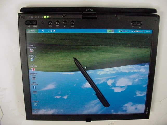
ANOX41T
May 02, 2005ThinkPad X41 Tablet Series
Equipment Class
DCD - Part 15 Low Power Transmitter Below 1705 kHz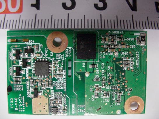
ANO20040700HER
Dec 08, 2004Model: J07M067 Bluetooth Standard Class 2 Adapter
Equipment Class
DSS - Part 15 Spread Spectrum Transmitter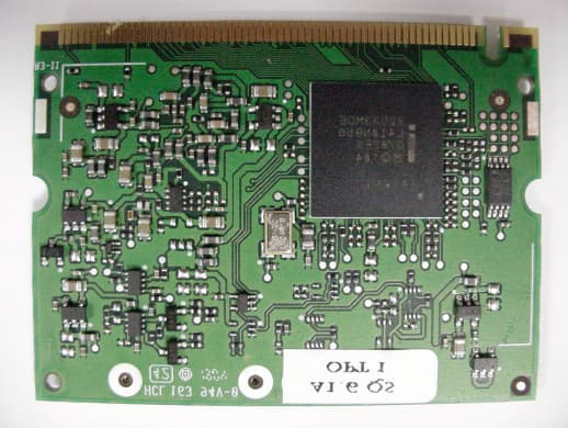
ANO20040601CX2
Oct 06, 2004Model: WM3B2915ABG (802.11a/b/g WLAN Adapter)
Equipment Class
DTS - Digital Transmission System