ANO20040501CX2Model: WM3B2200BG MoW (802.11b/g WLAN Adapter)
International Business Machines Corporation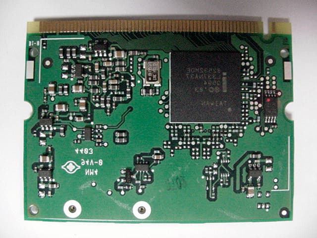
Click to zoom
Application Details
- Equipment Class
- DTS - Digital Transmission System
- Date of Grant
- Mar 03, 2004
- Application Purpose
- Original Equipment
- Date of Application
- Mar 03, 2004
- Equipment Note
- Model: WM3B2200BG MoW (802.11b/g WLAN Adapter)
- Frequency Range
- 2412.00000000 - 2462.00000000
- Country
- United States
Documents & Files
Document Text
Text extracted from the exhibit documents filed with the FCC. Open a document above to read the original.
Users Manual
FCC Test Report FCC ID: ANO20040501CX2 Document Number: FCC 19-0251-0 Prepared by T. Murota User’s Manual The attachment is the regulatory notices related to the FCC Part 15C and IC RSS-210 drawn from the user’s manual of the Model WM3B2200BG (Intel PRO/Wireless 2200BG Mini- PCI Adapter). Please see pages 1 and 9 through 12 for the related portion to the FCC rule concerning the applying LMA transmitter module. Part Number: 73P2815 Product warranty and notices for Model WM3B2200BG (Intel PRO/Wireless 2200BG Mini-PCI Adapter from IBM) Intel ® PRO/Wireless 2200BG Mini-PCI Adapter from IBM ® is supported for use with the following IBM ThinkPad ® series: v IBM ThinkPad X40 Series v IBM ThinkPad X30 Series For information concerning series and models announced after the publication of this notice, visit the Web site at www.ibm.com/pc/qtechinfo/MIGR-53286.html Read first – Regulatory information Note: To use Intel PRO/Wireless 2200BG Mini-PCI Adapter from IBM, a special type of BIOS, called “BIOS Lock,” must be installed on your ThinkPad computer. The “BIOS Lock” will function only on the authorized models named above. Intel PRO/Wireless 2200BG Mini-PCI Adapter from IBM marketed in US and Canada does not support nor function in the extended channels (12ch, 13ch). The Intel PRO/Wireless 2200BG Mini-PCI Adapter from IBM complies with the radio frequency and safety standards of any country or region in which it has been approved for wireless use. You are requested to install it and use your ThinkPad computer with this adapter in strict accordance with the instructions as described in the “Wireless regulatory notice” on page 9. Read first – Safety information Before installing this product, read the Safety Information. Antes de instalar este produto, leia as Informações de Segurança. © Copyright IBM Corp. 2004 1 Pred instalací tohoto produktu si prectete prírucku bezpecnostních instrukcí. Læs sikkerhedsforskrifterne, før du installerer dette produkt. Ennen kuin asennat tämän tuotteen, lue turvaohjeet kohdasta Safety Information. Avant d’installer ce produit, lisez les consignes de sécurité. Vor der Installation dieses Produkts die Sicherheitshinweise lesen. Prima di installare questo prodotto, leggere le Informazioni sulla Sicurezza. Lees voordat u dit product installeert eerst de veiligheidsvoorschriften. Les sikkerhetsinformasjonen (Safety Information) før du installerer dette produktet. Antes de instalar este produto, leia as Informações sobre Segurança. Pred inštaláciou tohto zariadenia si pečítaje Bezpečnostné predpisy. Antes de instalar este producto lea la información de seguridad. 2 Läs säkerhetsinformationen innan du installerar den här produkten. 3 General safety guidelines Always observe the following precautions to reduce the risk of injury and property damage. Service Do not attempt to service a product yourself unless instructed to do so by the IBM ® Support Center. Use only an IBM authorized service provider who is approved to repair your particular product. Note: Some parts can be upgraded or replaced by the customer. These parts are referred to as Customer Replaceable Units, or CRUs. IBM expressly identifies CRUs as such, and provides documentation with instructions when it is appropriate for customers to replace those parts. You must closely follow all instructions when performing such replacements. Always make sure that the power is turned off and that the product is unplugged from any power source before you attempt the replacement. If you have any questions or concerns, contact the IBM Support Center. Power cords and power adapters Use only the power cords and power adapters supplied by the product manufacturer. Never wrap a power cord around the power adapter or other object. Doing so can stress the cord in ways that can cause the cord to fray, crack or crimp. This can present a safety hazard. Always route power cords so that they will not be walked on, tripped over, or pinched by objects. Protect the cord and power adapters from liquids. For instance, do not leave your cord or power adapter near sinks, tubs, toilets, or on floors that are cleaned with liquid cleansers. Liquids can cause a short circuit, particularly if the cord or power adapter has been stressed by misuse. Liquids can also cause gradual corrosion of the power cord terminals and/or the connector terminals on the adapter which can eventually result in overheating. Always connect power cords and signal cables in the correct order and ensure that all power cord connectors are securely and completely plugged into receptacles. Do not use any power adapter that shows corrosion at the ac input pins and/or shows signs of overheating (such as deformed plastic) at the ac input or anywhere on the power adapter. 4 Do not use any power cords where the electrical contacts on either end show signs of corrosion or overheating or where the power cord appears to have been damaged in any way. Extension cords and related devices Ensure that extension cords, surge protectors, uninterruptible power supplies, and power strips that you use are rated to handle the electrical requirements of the product. Never overload these devices. If power strips are used, the load should not exceed the power strip input rating. Consult an electrician for more information if you have questions about power loads, power requirements, and input ratings. Plugs and outlets If a receptacle (power outlet) that you intend to use with your computer equipment appears to be damaged or corroded, do not use the outlet until it is replaced by a qualified electrician. Do not bend or modify the plug. If the plug is damaged, contact the manufacturer to obtain a replacement. Some products are equipped with a three-pronged plug. This plug fits only into a grounded electrical outlet. This is a safety feature. Do not defeat this safety feature by trying to insert it into a non-grounded outlet. If you cannot insert the plug into the outlet, contact an electrician for an …
Text truncated - open the document above for the full version.
Attestation Statements
FCC Test Report FCC ID: ANO20040501CX2 Document Number: FCC 19-0251-0 Prepared by T. Murota 1/1 Limited Modular Transmitter Approval Qualification 1. The modular transmitter has its own metal shielding covers on top side, which shields over the RF circuits in order for all modular transmitter emissions to comply with Part 15 limit and to prevent coupling between the RF circuitry of the module and any wires or circuits in the device into which the module is installed. Refer to the “External Photos” exhibit. 2. The modular transmitter has its own buffered modulation/data inputs. All inputs to the modules are buffered through the RF logic circuitry. Refer to the “Block Diagram” or “Schematic Diagrams” exhibits provided by Intel Corp. 3. The modular transmitter has its own power supply regulator and distributes necessary powers to all of its different circuits including the transmitter. Refer to the “Block Diagram” or “Schematic Diagrams” exhibits provided by Intel Corp. 4. The modular transmitter complies with the antenna requirements of Section 15.203 and 204(c) with an unique electrical antenna connector, so called “BIOS Lock”. Refer to the “Confidential_BIOS_Lock” exhibit. Each antenna system used for the applying module shall be approved(certified) with the module before each product’s announcement date. This application includes the built-in type antennas of IBM laptop computer, ThinkPad X30 Series and X40 Series. 5. The modular transmitter was tested in a stand-alone configuration with each built-in antenna of the host device that was connected to the proper AC adapter. It complies with the AC power line conducted requirements found in Section 15.207. 6. The modular transmitter is labeled with its own FCC ID number. Also the host device in which the modular transmitter is plugged has a label pointing the FCC ID number location. Please refer to the separate exhibit of the host antenna system, “Antenna_Info.pdf” exhibit. 7. The modular transmitter complies with the applied specific rule and operating requirements applicable to the transmitter, and the adequate instructions along with the module to be explained for customers are provided with the user’s manual. 8. The modular transmitter complies with the applicable RF exposure requirements. The proper RF exposure evaluations were performed with the host devices in line with the FCC Rules in Sections 2.1091 (MPE), since the antenna separation distance of 20cm or more from human’s body is maintained for the host device.
Cover Letter(s)
FCC Test Report FCC ID: ANO20040501CX2 Document Number: FCC 19-0251-0 Prepared by T. Murota 2/2 Outline of Submission 1. Objective This is a Certification Compliance Report for FCC Part 15 subpart C (Intentional Radiator). l FCC ID: ANO20040501CX2 l Model Number: WM3B2200BG l Advertising Name: Intel PRO/Wireless 2200BG Mini-PCI Adapter 2. Product Description The applying modular transmitter device is an OEM mini-PCI wireless LAN card supplied by Intel Corporation. The modular device complies with the following transmission modes. l IEEE802.11b (2.4GHz band DSSS) l IEEE802.11g (2.4GHz band OFDM) 3. Installation of the applying transmitter The applying LMA transmitter is a user installable wireless card. The supported host units for the device are IBM laptop PC ThinkPad X30 Series, and X40 Series. An electrical unique connector (so called “BIOS Lock”) is employed for the host devices to satisfy the FCC Part 15.203 or RSS-210 Ë5.5. This mechanism enables users to install the applying LMA transmitter to the specified host (ThinkPad X30 and X40 Series). The detail explanation of the unique coupling between the LMA transmitter and antenna systems is shown in the separate exhibit “Confidential_BIOS_Lock”, however IBM would like to hold it in confidence to maintain the secure "unique operability" with the applying card and IBM antenna systems. The BIOS Lock function is also effective for the user’s maintenance in replacing a broken card with a spare part. 4. Co-located Transmitters The applying LMA transmitter collocates with the following Bluetooth modules and transmits simultaneously. - FCC ID: ANO20020100MTN (IBM Integrated Bluetooth III with 56 Modem) - FCC ID: PI4BT-ULTRA (Bluetooth UltraPort Module from IBM) - FCC ID: PI4BT-IBM-PCII (Bluetooth PC Card II) As for the RF safety evaluation, refer to the separate exhibit “RF_Exposure.pdf ”.
External Photos
FCC Test Report FCC ID: ANO20040501CX2 Document Number: FCC 19-0251-0 Prepared by T. Murota 1/1 External Photos Top side (with shielding) Auxiliary Antenna terminal Main Antenna terminal Back side
ID Label/Location Info
FCC Test Report FCC ID: ANO20040501CX2 Document Number: FCC 19-0251-0 Prepared by T. Murota 1/1 Product Labeling Model Number FCC ID Top side
Internal Photos
FCC Test Report FCC ID: ANO20040501CX2 Document Number: FCC 19-0251-0 Prepared by T. Murota 1/1 Internal Photos Top side (without shielding) Auxiliary Antenna terminal Main Antenna terminal Back side (No shielding is assembled.)
Operational Description
FCC Test Report FCC ID: ANO20040501CX2 Document Number: FCC 19-0251-0 Prepared by T. Murota 1/16 Host Unit Antenna Information 1.Antenna Info of ThinkPad X30 Series........................................................................2 1.1Host PC Information................................................................................................................2 1.2Host PC Labeling....................................................................................................................4 1.3Antenna Specifications...........................................................................................................6 1.3.1Transmission Antenna assembly overview...........................................................................6 1.3.2Antenna Locations.............................................................................................................7 1.3.3Exterior Photos of Antennas...............................................................................................8 2.Antenna Info of ThinkPad X40 Series........................................................................9 2.1Host PC Information................................................................................................................9 2.2Host PC Labeling...................................................................................................................11 2.3Antenna Specifications..........................................................................................................13 2.3.1Transmission Antenna assembly overview..........................................................................13 2.3.2Antenna Locations............................................................................................................14 2.3.3Exterior Photos of Antennas..............................................................................................15 FCC Test Report FCC ID: ANO20040501CX2 Document Number: FCC 19-0251-0 Prepared by T. Murota 2/16 1. Antenna Info of ThinkPad X30 Series 1.1Host PC Information The two inverted F-figure type antennas are built in the left and right top sides of LCD as shown in the Photo. Those diversity antennas are not used simultaneously. One of the antennas is selected automatically or manually to have a good quality of radio communication. The selected antenna performs transmission or receiving in half duplex alternatively. Main Antenna Auxiliary Antenna The FCC ID and IC’s Certification Number are visible when the keyboard assembly is removed. FCC Test Report FCC ID: ANO20040501CX2 Document Number: FCC 19-0251-0 Prepared by T. Murota 3/16 IBM ThinkPad X30 Series Side View Rear View FCC Test Report FCC ID: ANO20040501CX2 Document Number: FCC 19-0251-0 Prepared by T. Murota 4/16 1.2Host PC Labeling Bottom view Front Side Applying LMA transmitter is installed under this location. See page 2. FCC Test Report FCC ID: ANO20040501CX2 Document Number: FCC 19-0251-0 Prepared by T. Murota 5/16 Label for a different model of the host PC (ThinkPad X30 Series) The model (X30) supports the applying transmitter and a built-in type Bluetooth LMA module which was granted separately for the host as the FCC ID: ANO20020100MTN on Feb/26/2003 (Class II). Bottom view Front Side The collocated user installable Bluetooth LMA transmitter is installed under this label. (Granted on Feb 26, 2003) FCC Test Report FCC ID: ANO20040501CX2 Document Number: FCC 19-0251-0 Prepared by T. Murota 6/16 1.3Antenna Specifications 1.3.1Transmission Antenna assembly overview IBM ThinkPad X30 Series DesignatorManufactureAntenna type Cable type and length Gain (dBi) Note 1) 08K4083 Main antenna Nissei Electric Ltd. (Japan) Dual Band Inverted F type Antenna coax 394mm 2.4GHz band 0.62 dBi (peak) 08K4084 Auxiliary antenna Nissei Electric Ltd. (Japan) Dual Band Inverted F type Antenna coax 534mm 2.4GHz band 1.28 dBi (peak) Note 1): 1a. Includes all cable losses. 1b. Antenna type should be Omni Directional and have gain of 2.0 dBi or less for IEEE802.11b & g (2.4GHz band) regarding the IBM internal specification. FCC Test Report FCC ID: ANO20040501CX2 Document Number: FCC 19-0251-0 Prepared by T. Murota 7/16 1.3.2Antenna Locations Auxiliary antenna Dual Band Inverted-F type P/N: 08K4084 Main antenna Dual Band Inverted-F type P/N: 08K4083 FCC Test Report FCC ID: ANO20040501CX2 Document Number: FCC 19-0251-0 Prepared by T. Murota 8/16 1.3.3Exterior Photos of Antennas Main Antenna (Left) Manufacturer: Nissei Electric Ltd. Parts Number: 08K4083 Dual Band Inverted-F type antenna Cable : coax 394 mm Auxiliary Antenna (Right) Manufacturer: Nissei Electric Ltd. Parts Number: 08K4084 Dual Band Inverted-F type antenna Cable : coax 534 mm FCC Test Report FCC ID: ANO20040501CX2 Document Number: FCC 19-0251-0 Prepared by T. Murota 9/16 2. Antenna Info of ThinkPad X40 Series 2.1Host PC Information The main and auxiliary meander antennas are built in the left and right top sides of LCD as shown in the Photo. Those diversity antennas are not used for transmission simultaneously. One of the antennas is selected automatically or manually to have a good quality of radio communication. The selected antenna performs transmission or receiving in half duplex alternatively. Main Antenna Auxiliary antenna FCC ID and IC’s Certification Number are visible when the card slot cover is removed. FCC Test Report FCC ID: ANO20040501CX2 Document Number: FCC 19-0251-0 Prepared by T. Murota 10/16 Side View Rear View IBM ThinkPad X40 Series FCC Test Report FCC ID: ANO20040501CX2 Document Number: FCC 19-0251-0 Prepared by T. Murota 11/16 2.2Host PC Labeling Bottom view, Back side The location where the applying LMA transmitter is to be installed. See page 9 and next page. FCC Test Report FCC ID: ANO20040501CX2 Document Number: FCC 19-0251-0 Prepared by T. Murota 12/16 Label for a different model of the host PC (ThinkPad X40 Series) The model (X40) supports the applying transmitter and a built-in …
Text truncated - open the document above for the full version.
RF Exposure Info
FCC Test Report FCC ID: ANO20040501CX2 Document Number: FCC 19-0251-0 Prepared by T. Murota 1/6 RF Exposure evaluation 1. RF Exposure evaluation for the applying LMA transmitter As shown below, the all transmission antennas of both host PC devices (IBM ThinkPad X30 and X40 Series) are located at the upper portions of each display (LCD) section, and the separation distance between each antenna and the human body is 20cm or more. Therefore the applying LMA transmitter and each antenna system is categorized as a mobile device by FCC CFR 47 Section 2.1091. The separation distance between the antenna and the human body (lap) is 21cm or more. IBM ThinkPad X30 Series IBM ThinkPad X40 Series Main antenna height Auxiliary antenna height The separation distance between the antenna and the human body (lap) is 21cm or more. Auxiliary antenna height Main antenna height IBM ThinkPad X40 Series FCC Test Report FCC ID: ANO20040501CX2 Document Number: FCC 19-0251-0 Prepared by T. Murota 2/6 [MPE evaluation] The following table shows the highest conducted peak output power values of the applying modular device, and the maximum peak antenna gains of each host device. Transmission mode P: conducted peak output power 2.4GHz band DSSS17.11dBm (51.4mW) 2.4GHz band OFDM13.30dBm (21.4mW) Host PC model G: peak antenna gain ThinkPad X30 Series1.28 dBi (Auxiliary antenna) ThinkPad X40 Series1.67 dBi (Auxiliary antenna) With those results, the maximum power density at 20cm distance is calculated as follows. IBM ThinkPad X30 Series Transmissio n mode EIRP = P + G (dBm) EIRP (mW) Max. power density S = EIRP/(4 % 20 2 % o) 2.4GHz band DSSS 18.3969.00.0137 mW/ cm 2 2.4GHz band OFDM 14.5828.70.0057 mW/ cm 2 IBM ThinkPad X40 Series Transmissio n mode EIRP = P + G (dBm) EIRP (mW) Max. power density S = EIRP/(4 % 20 2 % o) 2.4GHz band DSSS 18.7875.50.0150 mW/ cm 2 2.4GHz band OFDM 14.9731.40.0063 mW/ cm 2 Since the applying modular transmitter device does not function to emit the radio frequency from both diversity antennas simultaneously, the above results are the maximum values of RF exposure to the persons, and are far below the MPE limit (1.0 mW/ cm 2 ). Therefore the LMA transmitter meets the MPE requirements for general Population/Uncontrolled exposure. FCC Test Report FCC ID: ANO20040501CX2 Document Number: FCC 19-0251-0 Prepared by T. Murota 3/6 2. RF Exposure evaluation with co-located Bluetooth transmitters Collocated Bluetooth options for ThinkPad X30 Series (X31) The specific laptop PC, IBM ThinkPad X30 Series (X31) supports three kinds of Bluetooth devices as follows. Option typeFCC IDGrantee Name Product Name Granted DatePower in Test Report USB PI4BT-ULTRA Bluetooth Ultraport Module May/22/20011.4 mW PCMCIA PI4BT-IBM-PCII TDK Systems Europe Ltd. Blutooth PC Card II August/21/2001 1.0mW Built-in LMA Transmitter ANO20020100MTN IBM Japan, Ltd. IBM integrated Blutooth III with 56K Modem February/26/2003 2.58mW Built-in Bluetoot h Antenna USB Main antenna of applying PCMCIA 20cm m 20cm m 2.5cm Built-in antenna of ANO20020100MTN FCC Test Report FCC ID: ANO20040501CX2 Document Number: FCC 19-0251-0 Prepared by T. Murota 4/6 Co-located Bluetooth options for ThinkPad X40 Series The specific laptop PC, IBM ThinkPad X40 Series supports the following co-located Bluetooth device. Option typeFCC IDGrantee Name Product Name Granted DatePower in Test Report Built-in LMA Transmitter ANO20020100MTN IBM Japan, Ltd. IBM integrated Blutooth III with 56K Modem Under Class II process for the host (X40) 2.50mW 20cm Main antenna of applying transmitter Built-in antenna of Bluetooth FCC ID: ANO20020100MTN FCC Test Report FCC ID: ANO20040501CX2 Document Number: FCC 19-0251-0 Prepared by T. Murota 5/6 The main and auxiliary antennas located at LCD section of each host device (ThinkPad X30 Series, or X40 Series) are assembled apart from each Bluetooth antenna shown in the previous pages with 20 cm or more. Therefore, those co-located Bluetooth transmitters are allowed to evaluate the RF exposure compliance independently of the applying modular transmitter. In other word, the SAR testing for the applying transmitter in co-locating with those Bluetooth transmitters is not required, when the Bluetooth transmitters could satisfy the RF exposure requirement with those own transmission powers. When a customer operates the applying PC on one’s lap, the sufficient separation distance (minimum 20cm) between the above Bluetooth antennas and the person’s body (lap) can not be maintained. But the footnote of the Section 3 in Supplement C to OET Bulletin 65 states : “ 14 ...... If a device, its antenna or other radiating structures are operating at closer than 2.5 cm from a person’s body or in contact with the body, SAR evaluation may be necessary when the output is more than 50 – 100 mW, depending on the device operating configurations and exposure conditions.” The total output power of the three Bluetooth transmitters in the previous table does not exceed 5mW (far below 50mW). Therefore these transmitters also satisfy the RF exposure requirement regarding CFR 47 Part 15.247(b)(4) without a SAR compliance test report, and can operate with the applying transmitter simultaneously. IBM Web site provides customers the grant conditions for the co-locating use and approved co- located Bluetooth devices. See the next page. FCC Test Report FCC ID: ANO20040501CX2 Document Number: FCC 19-0251-0 Prepared by T. Murota 6/6 3. IBM Web site Note) The info for the applying LMA transmitter is not available until the product announcement. http://www.pc.ibm.com/qtechinfo/MIGR-53286.html
Test Report
FCC Test Report, FCC ID: ANO20040501CX2 Document Number: FCC 19-0251-0 Prepared by T. Asano 2/112 MEASUREMENT / TECHNICAL REPORT – Part 15 Subpart C (Intentional Radiator) Model: WM3B22-U (802.11b/g Wireless LAN Adapter) with IBM ThinkPad X30 Series (Machine Type: 2672, 2673, 2890, 2891) and IBM ThinkPad X40 Series (Machine Type: 2369, 2370, 2371, 2372, 2381) FCC ID : ANO20040501CX2 February 6, 2004 This report concerns: (check one) Original Grant ̧ Class I change Class II change Equipment type: Wireless LAN device This report shall not be reproduced except in full, without the written permission of this test lab. The measurement results contained in this report relate only to the item which was tested. Measurement procedure used is ANSI C63.4-2000 unless otherwise specified. Other test procedure: The FCC has issued provisional acceptance of this test laboratory for Declaration of Conformity testing per letter dated 1997. APPLICANT ANTI-DRUG ABUSE CERTIFICATION: By checking yes, the applicant certifies that, in the case of an individual applicant, he or she is not subject to a denial of federal benefits, that includes FCC benefits, pursuant to Section 5301 of the Anti-Drug Abuse of 1988, 21 U.S.C. 853(a), or, in the case of a non-individual applicant (e.g. corporation, partnership or other unincorporated association), no party to the application is subject to a denial of federal benefits, that includes FCC benefits, pursuant to that section. For the definition of a “party” for these purposes, see 47 CFR 1.2002(b). Yes or No “Report shall not be reproduced except in full, without the written approval of the laboratory” “the report must not be used by the client to claim product endorsement by NVLAP or any agency of the US government” Prepared by: Takeshi Asano IBM Japan Corporation, Yamato EMC Enginnering LAB-S59, 1623-14, Shimotsuruma, Yamato-shi Kanagawa-ken 242-8502, Japan Tel: +81-46-215-4779 Fax: +81-46-273-7420 FCC Test Report, FCC ID: ANO20040501CX2 Document Number: FCC 19-0251-0 Prepared by T. Asano 3/112 - Index - A.General Information.................................................................................................................5 A.1Test Methodology..................................................................................................................................................................5 A.2Test Facility / NVLAP Accreditation...............................................................................................................................5 A.3EUT details............................................................................................................................................................................5 B.Summary of Test Results...........................................................................................................6 C.Operation Mode of EUT...........................................................................................................7 D.Justification................................................................................................................................7 E.Test Instruments.......................................................................................................................8 F.Measurement Uncertainty...........................................................................................................9 G.Temperature and Humidity......................................................................................................9 H.Related Submittal(s)/Grant(s)/Notes.......................................................................................9 1.Bandwidth at 6 dB below............................................................................................................10 1.1Test Procedure.....................................................................................................................................................................10 1.2Test Instruments and Measurement Setup..................................................................................................................10 1.3Measurement Results........................................................................................................................................................10 1.4Trace Data of 6dB bandwidth.........................................................................................................................................12 2.Occupied Bandwidth (20 dB Bandwidth).................................................................................18 2.1Test Procedure.....................................................................................................................................................................18 2.2Test Instruments and Measurement Setup..................................................................................................................18 2.3Measurement Results........................................................................................................................................................18 2.4Trace Data of Occupied Bandwidth..............................................................................................................................20 3.Conducted Peak Output Power.................................................................................................26 3.1Test Procedure.....................................................................................................................................................................26 3.2Test Instruments and Measurement Setup..................................................................................................................26 3.3Measurement Results........................................................................................................................................................26 3.4Trace Data of Conducted Peak Output Power...…
Text truncated - open the document above for the full version.
Test Setup Photos
FCC Test Report FCC ID: ANO20040501CX2 Document Number: FCC 19-0251-0 Prepared by T. Murota 1/4 Test Setup Photos EMI - Radiated Measurement Photos FCCICTest Items 15.205 / 15.2096.2.1 / 6.2.2(o)(e3) / 6.3 General Field Strength Limits (Restricted Bands and Radiated Emission Limits) Tx 15.205 / 15.2096.2.1 / 6.2.2(o)(e3) / 7.3 General Field Strength Limits (Restricted Bands and Radiated Emission Limits) Rx Semi-anechoic Chamber #1 FCC Test Report FCC ID: ANO20040501CX2 Document Number: FCC 19-0251-0 Prepared by T. Murota 2/4 EMI Radiated measurement photos Rear view Front view FCC Test Report FCC ID: ANO20040501CX2 Document Number: FCC 19-0251-0 Prepared by T. Murota 3/4 EMI - Conducted Measurement Photos FCCICTest Items 15.207 6.2.2(o)(e3) / 6.6 AC Wireline Conducted emissionsTx 15.207 6.2.2(o)(e3) / 7.4 AC Wireline Conducted emissionsRx EMI conducted room (shield room) FCC Test Report FCC ID: ANO20040501CX2 Document Number: FCC 19-0251-0 Prepared by T. Murota 4/4 Conducted Measurement Photos FCCICMeasurement Items 15.247(a)(2) Bandwidth at 6 dB blow 15.247(b)(3) 6.2.2(o)(b) Peak output power 15.247(c)5.9.1 6.2.2(o)(e1) Out of Band Emissions IC: Occupied BW (20dB BW) 15.247(d)6.2.2(o)(b) Transmitter power spectral density Tx EMI Semi-anechoic Chamber #1, Operation Room ThinkPad X40 Series ThinkPad X30 Series Antenna cable
Contact Information
Applicant
John Maas(Corp Program Manager EMC)
Technical Contact
PCTEST Engineering Laboratory Inc.Randy Ortanez
[email protected]410-290-6652
6660-B Dobbin Road · Columbia, Maryland · United States
Test Firm
IBM JapanAkihisa Sakurai
Technical Specifications
| # | Rule Parts | Frequency Range | Power Output |
|---|---|---|---|
| 1 | 15C | 2.41 GHz - 2.46 GHz | 51.40 mW |
Other Applications from International Business Machines Corporation

ANO-7054SC
Jun 30, 2005Bluetooth Enabled Handheld Scanner
Equipment Class
DSS - Part 15 Spread Spectrum Transmitter
ANO-7054
Jun 28, 2005Model 7054 Mobile Tablet
Equipment Class
DTS - Digital Transmission System
ANOX41T
May 02, 2005ThinkPad X41 Tablet Series
Equipment Class
DCD - Part 15 Low Power Transmitter Below 1705 kHz
ANO20040700HER
Dec 08, 2004Model: J07M067 Bluetooth Standard Class 2 Adapter
Equipment Class
DSS - Part 15 Spread Spectrum Transmitter
ANO20040601CX2
Oct 06, 2004Model: WM3B2915ABG (802.11a/b/g WLAN Adapter)
Equipment Class
DTS - Digital Transmission System