ASIK4V003RFID For JVC Card Printer
JVC KENWOOD Corporation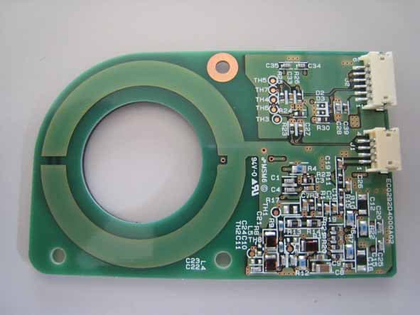
Click to zoom
Application Details
- Equipment Class
- DXT - Part 15 Low Power Transceiver, Rx Verified
- Date of Grant
- Jun 01, 2007
- Application Purpose
- Original Equipment
- Date of Application
- Jun 01, 2007
- Equipment Note
- RFID For JVC Card Printer
- Frequency Range
- 13.56000000 - 13.56000000
- Company
- JVC KENWOOD Corporation
- Country
- Japan
Documents & Files
Document Text
Text extracted from the exhibit documents filed with the FCC. Open a document above to read the original.
Users Manual
KAT- T274-001 Jam (TurnOver) Jam (Hopper) HR is too hot. Please remove MEDIA FILM Please, Power Off. >Ink> >Cleaning >Counter Reset >Display> Ready MENU Sublimation type retransfer printer Model Error codes Setting the cards Care Operation and Setting the various modes Ink replacementConnection *** CX-330 Instruction Manual See p.11~12,21 See p.14~17 See p.18~20 See p.25~39 See p.40~44 See p.46~47 •Thank for purchasing this product. •Please read this manual carefully before use to ensure correct operation. It is particularly important to read the Safety Precautions for safe operation. After reading, retain this manual carefully for future reference. •The product number is important for quality control. Upon purchase, check the back of the unit to make sure that the product number is correctly displayed. Notes about this manual (1)This manual may not be reprinted in any way without permission. (2)The contents of this manual, as well as the specifications and design of this product, may change without notice. (3)The illustrations used in this manual may differ slightly from the actual product. 2 3 NOTE: This equipment has been tested and found to comply with the limits for a Class B digital device, pursu- ant to part 15 the FCC Rules. These limits are designed to provide reasonable protection against harmful interference in a residential installation. This equipment generates, uses and can radiate radio frequency energy and, if not installed and used in accordance with the instructions, may cause harmful interference to radio communications. However, there is no guarantee that interference will not occur in a particular installation. If this equipment does cause harmful interference to radio or television recep- tion, which can be determined by turning the equipment off and on, the user is encouraged to try to correct the interference by one or more of the following measures: – Reorient or relocate the receiving antenna. – Increase the separation between the equipment and receiver. – Connect the equipment into an outlet on a circuit different from that to which the receiver is con- nected. – Consult the dealer or an experienced radio/TV technician for help. Caution: Changes or modifications not approved by party responsible for compliance could void user's authority to operate the equipment. Machine noise Sound power level: less than 70dB(A) according to DIN45635 part 19 (EN27779). The measurements are to be made according to DIN45635 part 2019 or EN27779, respectively. Information for USA Information for EU Information for Canada Operation is subject to the following two conditions: (1) this device may not cause interference, and (2) this device must accept any interference, including interference that may cause undesired operation of the device. 4 Contents Notes for safe operation ................................ 5 Before use ..................................................... 7 Product features .................................................... 7 Checking accessories............................................ 7 Contents of attached CD-ROM.............................. 7 Handling of transfer film, ink ribbons and cards .... 7 Handling ............................................................. 7 Storage .............................................................. 7 Storing and handling cards after printing ........... 8 Purchasing print media and cards ..................... 8 Escape Clause ...................................................... 8 Installation ............................................................. 9 Installation diagram ............................................ 9 Names of parts ............................................ 10 Front................................................................. 10 Rear ................................................................. 10 When the printer door is open.......................... 10 Set-up.......................................................... 11 Connecting the IC unit (sold separately) ............. 11 Large size IC unit (sold separately) ................. 11 Medium-type IC unit and Compact IC unit (sold separately) ....................................................... 12 Connecting the Laminator ................................... 12 Connecting the power cord.................................. 13 Installing the card stacker .................................... 14 Discharging the card ........................................ 14 Setting the ink ribbon ........................................... 15 Setting the retransfer film .................................... 17 Caution when loading the retransfer film cassette and/or the ink ribbon cassette ............................. 19 Setting cards........................................................ 19 Inserting cards ................................................. 19 When using magnetic cards............................. 21 When using contact IC cards ........................... 21 Loading cards .................................................. 21 Switching the card thickness............................ 21 Connecting with a host computer ........................ 22 USB cable connection ....................................... 22 LAN cable connection ....................................... 22 Software Licencing Agreement .......................... 23 Operation Environment...................................... 23 About Software .................................................. 23 Connecting Multiple Printers ............................... 23 Installation of Software ........................................ 23 The copyright of the software is displayed .......... 23 Before use ................................................... 24 Names of parts on the operation panel ............... 24 Setting buttons ................................................. 24 Operation display LED ..................................... 24 LCD panel ..............................…
Text truncated - open the document above for the full version.
Cover Letter(s)
VICTOR COMPANY OF JAPAN, LIMITED 3-12,Moriya-cho, Kanagawa-ku, Yokohama 221-0022, Japan 2007/05/10 Compliance Certification Services Certification Division 561F Monterey Road Morgan Hill, CA 95037 To whom it may concern: We, the undersigned, hereby authorize EMC Kashima Corporation, to act on our behalf in all manners relating to application for equipment authorization, including signing of all documents relating to these matters. Any and all acts carried out by EMC Kashima Corporation on our behalf shall have the same effect as acts of our own. We, the undersigned, hereby certify that we are not subject to a denial of federal benefits, that includes FCC benefits, pursuant to Section 5301 of the Anti-Drug Abuse Act of 1988, 21 U.S.C. 853(a). In authorizing EMC Kashima Corporation as our agent, we still recognize that we are responsible to: a) comply with the relevant provisions of the certification program; b) make all necessary arrangements for the conduct of the evaluation, including provision for examining documentation and access to all areas, records (including internal audit reports) and personnel for the purposes of evaluation (e.g. testing, inspection, assessment, surveillance, reassessment) and resolution of complaints; c) make claims regarding certification only in respect of the scope for which certification has been granted; d) do not use our product certification in such a manner as to bring the Certification Division into disrepute and not make any statement regarding our product certification which the Certification Division may consider misleading or unauthorized; e) upon suspension or cancellation of certification, discontinue use of all advertising matter that contains any reference thereto and return any certification documents as required by the Certification Division; f) use certification only to indicate the products are certified as being in conformity with specified standards; g) endeavor to ensure that no certificate or report nor any part thereof is used in a misleading manner; h) ensure that any reference to our product certification in communication media such as documents, brochures or advertising, complies with the requirements of the Certification Division; i) keep a record of all complaints made known to the us relating to the product’s compliance with requirements of the relevant standard and to make these records available to the Certification Division when requested; j) take appropriate action with respect to such complaints and any deficiencies found in products or services that affect compliance with the requirements for certification; k) document the actions taken. This authorization is valid until further written notice from the applicant. Sincerely Yours, Makoto Hayase Engineer Engineering Dept. DS Task Printer Group Professional System Business Group Victor Company of Japan, Limited REMARK : 1. This authorization letter will be sent along with your application when filing with the Certification Division. 2. Please follow the format and type it on company letterhead and send original to us.
Cover Letter(s)
2007.5.9 Victor Company of Japan, Limited Hachioji Plant 2969-2 Ishikawa-cho, Hachioji-shi, Tokyo 192-8620, Japan RFID Unit informations Manufacturer: UMC Electronics Co., Ltd. Model: KBB0007-001 Antenna Gain : -60.5dB
Cover Letter(s)
1 Chris Harvey From: [email protected] Sent: Wednesday, May 30, 2007 12:35 AM To: [email protected] Subject: Re: Victor Company of Japan Ltd, FCC ID: ASIK4V003, Assessment NO.: AN07T6831, Notice#1 Attachments: ASIK4V003 Label and Location 2.pdf; ASIK4V003 Request for LMA 2.pdf ASIK4V003 Label and Location 2... ASIK4V003 Request for LMA 2.pd... Dear Mr. Harvey, Thank you for your e-mail regarding TCB Application. I answer as follows. 1. Please provide the return frequency of the passive tag? This frequency must be within the allowed band of FCC 15.225. -----The tag uses the same frequency as the RFID Unit. 2. The compliance information from FCC 15.19 must be located on the device since this device is sufficiently large to allow the labeling (even though the information has been contained in the manual). -----Please see the attached revised file of the Label and Location. 3. The module does not contain shielding as required by the FCC Modular approval procedure. A Limited Modular Approval may be issued if it can be shown that compliance is ensured in each configuration. The FCC has required shielding of modules to ensure that there is no unintended coupling to/from the circuits of the EUT or host. The FCC has recently clarified this position in FCC 07-56, new Rule section 15.212: Please update your Modular Approval cover letter to indicate how the shielding requirement is met. -----Please see the attached revised file of the Request for LMA. 4. The labeling requirements for modules is that the module be labeled and a separate label on the outside of the host to indicate that the module is, referencing the FCC ID of the host installed (example: "This Device Contains FCC ID: xxxx). Please update the labeling exhibit to show the EUT label on the module and the host label example for this product. -----Please see the attached revised file of the Label and Location. Best regards, [email protected] wrote: > Dear Kenichi Suda-san > You are listed as the technical contact for the above referenced TCB Application., The following items need to be addressed before the review can be continued: > > 1. Please provide the return frequency of the passive tag? This frequency must be within the allowed band of FCC 15.225. > > 2. The compliance information from FCC 15.19 must be located on the device since this device is sufficiently large to allow the labeling (even though the information has been contained in the manual). > > 3. The module does not contain shielding as required by the FCC Modular approval 2 procedure. A Limited Modular Approval may be issued if it can be shown that compliance is ensured in each configuration. The FCC has required shielding of modules to ensure that there is no unintended coupling to/from the circuits of the EUT or host. The FCC has recently clarified this position in FCC 07-56, new Rule section 15.212: > > New 15.212 (b) A limited modular approval may be granted for single or split modular transmitters that do not comply with all of the above requirements, e.g., shielding, minimum signaling amplitude, buffered modulation/data inputs, or power supply regulation, if the manufacturer can demonstrate by alternative means in the application for equipment authorization that the modular transmitter meets all the applicable Part 15 requirements under the operating conditions in which the transmitter will be used. Limited modular approval also may be granted in those instances where compliance with RF exposure rules is demonstrated only for particular product configurations. The applicant for certification must state how control of the end product into which the module will be installed will be maintained such that full compliance of the end product is always ensured. > > Please update your Modular Approval cover letter to indicate how the shielding requirement is met. > > 4. The labeling requirements for modules is that the module be labeled and a separate label on the outside of the host to indicate that the module is, referencing the FCC ID of the host installed (example: "This Device Contains FCC ID: xxxx). Please update the labeling exhibit to show the EUT label on the module and the host label example for this product. > > The items indicated above must be submitted before processing can continue on the above referenced application. Failure to provide the requested information within 30 days of the original e-mail date may result in application dismissal and forfeiture of the filing fee. Also, please note that partial responses increase processing time and should not be submitted. Any questions about the content of this correspondence should be directed to the e-mail address listed below the name of the sender. > > Bewst regards, > > Chris Harvey > [email protected] > > > > -- ===================== Ken'ichi Suda EMC Kashima Corporation 1614 Mushihata,Katori-shi,Chiba-ken 289-0341 Japan TEL: 81-478-82-0963 FAX: 81-478-82-3373 http://www.emc-kashima.co.jp =====================
ID Label/Location Info
RATING LABELLS41171-002AS=1/1 MODEL CX-330 FCC ID : ASIK4V003 IC : 2320A-K3U003 LS41171-002A H achioji Factory -002B Card Printer MODEL CX-330 SERIAL NO. ID.NO. CX-330.....
Internal Photos
RF-ID Unit Antenna RF-ID tag
Operational Description
Description of The EUT Product features In this printer a special ink ribbon for sublimation type printing used. The ink ribbon bobbin has a RF-ID tag (passive type) built inside. The radio communication between the printer and the ink ribbon bobbin give the following functions, of which no user is informed. 1. Discerning the type of ink ribbon This printer can automatically discern what type of ink ribbon is installed out of the various options, for example, both sides full color, one side full color rear side monochrome, and so on. 2. Managing the number of used picture frames in an ink ribbon. The information on the number of used/remained picture frames can be got by writing the number of used picture frame into the RF-ID tag, even when ink ribbons are exchanged. 3. By using the RF-ID tag, the printer could distinguish between a proper ink and inadequite one so the defective printing would be prevented.
Test Report
Test Report No.: TR2-07212F Model: KBB0007-001 FCC ID: ASIK4V003 EMC Kashima Corporation Page 1 of 25 1614, Mushihata, Omigawa-machi, Katori-gun, Chiba-ken, 289-0341 Japan TEL +81-478-82-0963, FAX +81-478-82-3373 http://www.emc-kashima.co.jp Rev.8.4F EMISSION -- TEST REPORT TEST REPORT No.: TR2-07212F Date of Issue: May 11, 2007 KIND OF EQUIPMENT: RF-ID Unit MODEL: KBB0007-001 APPLICANT: Victor Company of Japan, Limited FCC ID: ASIK4V003 TEST STANDARD(S): FCC Part 15 Subpart C, Section 15.225 TEST RESULT: Complied It is not allowed to copy this report even partly without the written allowance of the test laboratory. The test result only responds to the tested sample. The report must not be used to claim products endorsement by the accreditation or authorization body. The engineers of EMC Kashima Corporation were not involved in modification for the tested sample. TEST DATE(S): April 10, 11, 17, 2007 TEST ENGINEER(S): Kazuhiro Ando Manager APPROVED BY : Ken'ichi Suda Director Test Report No.: TR2-07212F Model: KBB0007-001 FCC ID: ASIK4V003 EMC Kashima Corporation Page 2 of 25 1614, Mushihata, Omigawa-machi, Katori-gun, Chiba-ken, 289-0341 Japan TEL +81-478-82-0963, FAX +81-478-82-3373 http://www.emc-kashima.co.jp Rev.8.4F TABLE OF CONTENTS Page 1 General Information 3 2 Summary of Test Result 4 3 Equipment Under Test (EUT) 5 4 Test Configuration 6 5 Test Facilities 8 6 Measurement Uncertainty 8 7 Test Conditions 9 8 Test Data 14 8.1 Conducted Emissions (Mains) 150 kHz - 30 MHz 14 8.2 Radiated Emissions 9 kHz - 30 MHz 15 8.3 Radiated Emissions 30 MHz - 1000 MHz 17 8.4 Frequency stability 20 8.5 20dB Bandwidth 21 9 The Photos of Test-Setup 22 Test Report No.: TR2-07212F Model: KBB0007-001 FCC ID: ASIK4V003 EMC Kashima Corporation Page 3 of 25 1614, Mushihata, Omigawa-machi, Katori-gun, Chiba-ken, 289-0341 Japan TEL +81-478-82-0963, FAX +81-478-82-3373 http://www.emc-kashima.co.jp Rev.8.4F 1 GENERAL INFORMATION 1.1 APPLICANT Victor Company of Japan, Limited 1.2 ADDRESS 2969-2, Ishikawa-cho, Hachioji-shi, Tokyo 192-8620, Japan 1.3 MANUFACTURER UMC Electronics Ltd. 1.4 KIND OF EQUIPMENT RF-ID Unit 1.5 MODEL KBB0007-001 1.6 POWER RATING DC5V ±5% 1.7 PROTECTION CLASS Class III 1.8 TESTING VOLTAGE DC5V from Card Printer (AC120V, 60Hz) 1.9 CONDITION OF EUT Production 1.10 OPETATING FREQUENCY 13.56MHz 1.11 TYPE OF MODURATION ASK 1.12 OPETATING TEMPERATUR 0 °C to 50 °C 1.13 TEST STANDARD(S) FCC Part 15 Subpart C, Section 15.225 1.14 TEST METHOD(S) ANSI C63.4: 2003 1.15 TESTED DATE(S) April 10, 11, 17, 2007 1.16 REMARK(S) Test Report No.: TR2-07212F Model: KBB0007-001 FCC ID: ASIK4V003 EMC Kashima Corporation Page 4 of 25 1614, Mushihata, Omigawa-machi, Katori-gun, Chiba-ken, 289-0341 Japan TEL +81-478-82-0963, FAX +81-478-82-3373 http://www.emc-kashima.co.jp Rev.8.4F 2 SUMMARY OF TEST RESULT FCC Part 15 Section Test Item Worst margin Condition Result 15.203 Antenna requirement - - Pass Note1 15.207 Conducted emissions 9kHz - 30MHz 15.2dB at 0.2548MHz - Pass 15.225(a)(b)(c) Radiated emissions 9kHz - 30MHz 60.8dB at 13.56MHz Radiated Pass 15.225(d) Radiated emissions 9kHz - 30MHz 51.3dB at 27.12MHz Radiated Pass 15.225(d) 15.209 Radiated emissions 30MHz - 1GHz 5.1dB at 81.35MHz Radiated Pass 15.225(e) Frequency stability -0.00383% Radiated Pass 15.215(c) 20dB Bandwidth 6.32kHz Radiated Pass Note 1: Users cannot replace the antenna since it is attached to the inside of the printer. Note 2: “Pass” is only based on the measurement data and it does not include the measurement uncertainty. Accordingly, the statement below is applied to the test result. - It is possible to determine compliance at a level of confidence of 95% in case that the margin is not less than the measurement uncertainty in the Laboratory. - It is not possible to determine compliance at a level of confidence of 95% in case that the margin is less than the measurement uncertainty in the Laboratory. However, the measured result indicates that the product tested complies with the specification limit. Test Report No.: TR2-07212F Model: KBB0007-001 FCC ID: ASIK4V003 EMC Kashima Corporation Page 5 of 25 1614, Mushihata, Omigawa-machi, Katori-gun, Chiba-ken, 289-0341 Japan TEL +81-478-82-0963, FAX +81-478-82-3373 http://www.emc-kashima.co.jp Rev.8.4F 3 EQUIPMENT UNDER TEST 3.1 Description of The EUT Purpose of using the radio device In this printer a special ink ribbon for sublimation type printing used. The ink ribbon bobbin has a RF-ID tag (passive type) built inside. The radio communication between the printer and the ink ribbon bobbin give the following functions, of which no user is informed. 1. Discerning the type of ink ribbon This printer can automatically discern what type of ink ribbon is installed out of the various options, for example, both sides full color, one side full color rear side monochrome, and so on. 2. Managing the number of used picture frames in an ink ribbon. The information on the number of used/remained picture frames can be got by writing the number of used picture frame into the RF-ID tag, even when ink ribbons are exchanged. 3. By using the RF-ID tag, the printer could distinguish between a proper ink and inadequite one so the defective printing would be prevented. 3.2 Typically Used Frequencies Frequency Derived Frequency Description of Use Remarks 13.56 MHz 13.56 MHz RF-ID 20 MHz 20 MHz RF-ID PWB CPU Highest Frequency 3.2 Operation - mode of The EUT The equipment under test was operated during the measurement under following conditions: - Transmit mode Test Report No.: TR2-07212F Model: KBB0007-001 FCC ID: ASIK4V003 EMC Kashima Corporation Page 6 of 25 1614, Mushihata, Omigawa-machi, Katori-gun, Chiba-ken, 289-0341 Japan TEL +81-478-82-0963, FAX +81-478-82-3373 http://www.emc-kashima.co.jp Rev.8.4F 4 TEST CONFIGURATION 4.1 EUT(s) and Peripheral(s) Equipment Name Model Serial No. Company FCC ID A RF-ID Unit (EUT) KBB0007-001 005491 JVC ASIK4V003 B Card Printer CX-330 082J0014 JVC DoC* *Note: Declaration of Con…
Text truncated - open the document above for the full version.
Test Setup Photos
Test Report No.: TR2-07212F Model: KBB0007-001 FCC ID: ASIK4V003 EMC Kashima Corporation Page 22 of 25 1614, Mushihata, Omigawa-machi, Katori-gun, Chiba-ken, 289-0341 Japan TEL +81-478-82-0963, FAX +81-478-82-3373 http://www.emc-kashima.co.jp Rev.8.4F 9 THE PHOTOS OF TEST-SETUP 9.1 Conducted Emissions 150 kHz - 30 MHz Test Report No.: TR2-07212F Model: KBB0007-001 FCC ID: ASIK4V003 EMC Kashima Corporation Page 23 of 25 1614, Mushihata, Omigawa-machi, Katori-gun, Chiba-ken, 289-0341 Japan TEL +81-478-82-0963, FAX +81-478-82-3373 http://www.emc-kashima.co.jp Rev.8.4F 9.2 Radiated Emissions 9 kHz - 1000 MHz Test Report No.: TR2-07212F Model: KBB0007-001 FCC ID: ASIK4V003 EMC Kashima Corporation Page 24 of 25 1614, Mushihata, Omigawa-machi, Katori-gun, Chiba-ken, 289-0341 Japan TEL +81-478-82-0963, FAX +81-478-82-3373 http://www.emc-kashima.co.jp Rev.8.4F Radiated Emissions 9 kHz - 1000 MHz X-axis Y-axis Z-axis Test Report No.: TR2-07212F Model: KBB0007-001 FCC ID: ASIK4V003 EMC Kashima Corporation Page 25 of 25 1614, Mushihata, Omigawa-machi, Katori-gun, Chiba-ken, 289-0341 Japan TEL +81-478-82-0963, FAX +81-478-82-3373 http://www.emc-kashima.co.jp Rev.8.4F 9.3 Frequency Stability
Contact Information
Applicant
Yasukazu Katakai(Manager)
Test Firm
UL Japan, IncKenichi Suda
Technical Specifications
| # | Rule Parts | Frequency Range | Power Output |
|---|---|---|---|
| 1 | 15C | 13.56 MHz - 13.56 MHz | - |
Other Applications from JVC KENWOOD Corporation

ASIZWSA1
Jul 27, 2020SMART HEADSETS
Equipment Class
DSS - Part 15 Spread Spectrum Transmitter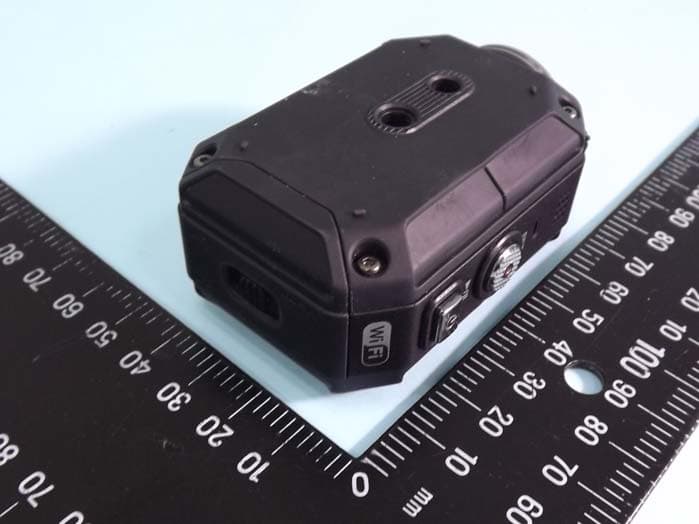
ASIP4C101
Jul 11, 2012Action Camera
Equipment Class
DTS - Digital Transmission System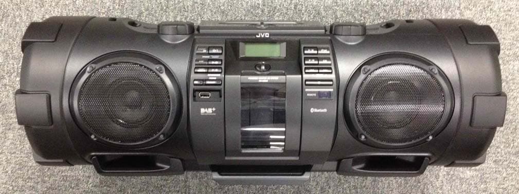
ASIVCB008
Apr 17, 2012POWERED WOOFER CD SYSTEM
Equipment Class
DSS - Part 15 Spread Spectrum Transmitter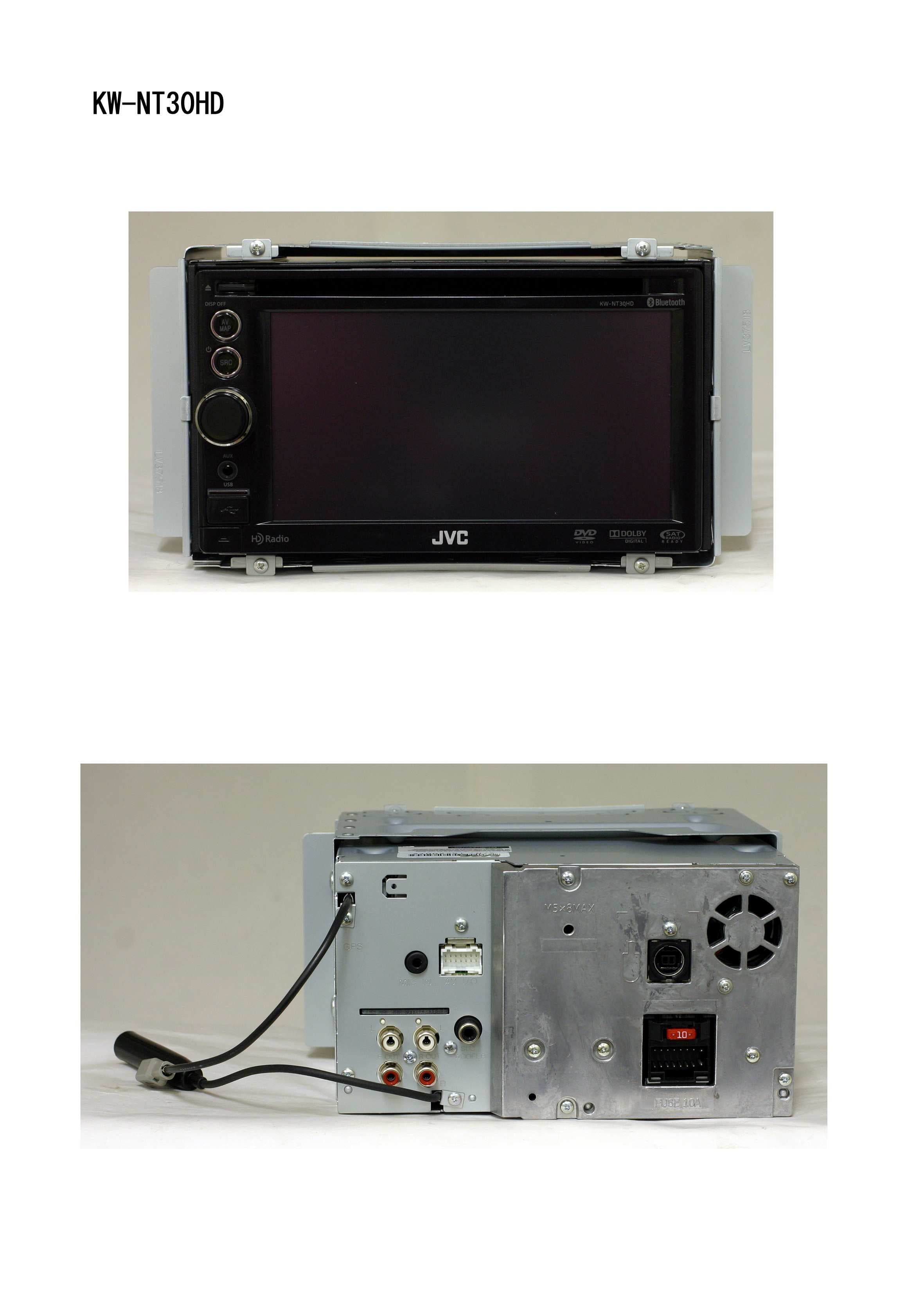
ASIV1B007
Jan 31, 2011GPS Navigation System
Equipment Class
DSS - Part 15 Spread Spectrum Transmitter
ASIVBA006
Nov 29, 2010Bluetooth audio adaptor for vehicle use.
Equipment Class
DSS - Part 15 Spread Spectrum Transmitter