ASIV1B007GPS Navigation System
JVC KENWOOD Corporation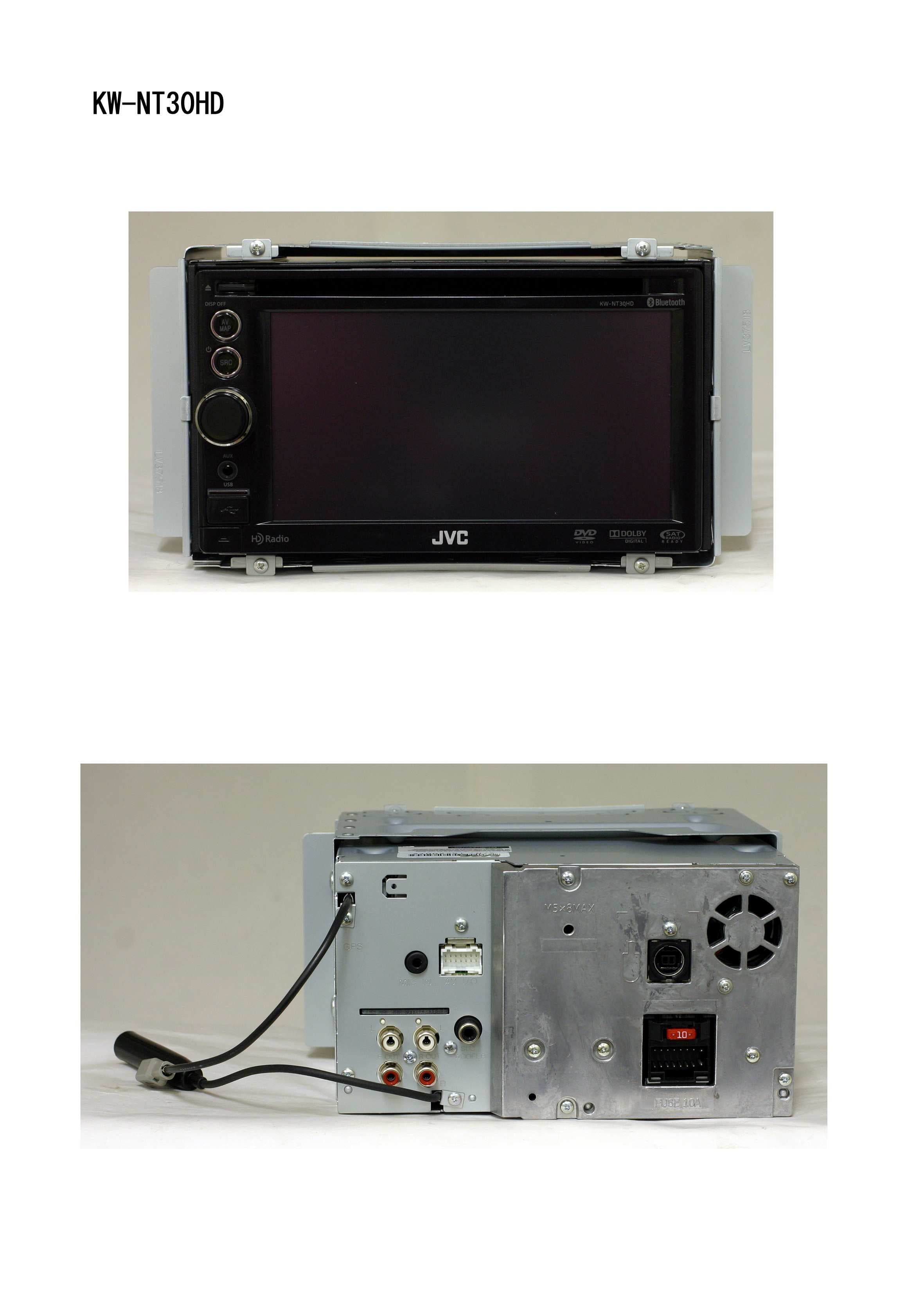
Click to zoom
Application Details
- Equipment Class
- DSS - Part 15 Spread Spectrum Transmitter
- Date of Grant
- Jan 31, 2011
- Application Purpose
- Original Equipment
- Date of Application
- Jan 31, 2011
- Equipment Note
- GPS Navigation System
- Frequency Range
- 2402.00000000 - 2480.00000000
- Company
- JVC KENWOOD Corporation
- Country
- Japan
Documents & Files
Document Text
Text extracted from the exhibit documents filed with the FCC. Open a document above to read the original.
Users Manual
ENGLISH ESPAÑOL FRANÇAIS ESPAÑOL For installation and connections, refer to the separate manual. Para la instalación y las conexiones, refiérase al manual separado. Pour l’installation et les raccordements, se référer au manuel séparé. INSTRUCTIONS MANUAL DE INSTRUCCIONES MANUEL D’INSTRUCTIONS For customer Use: Enter below the Model No. and Serial No. which are located on the top or bottom of the cabinet. Retain this information for future reference. Model No. Serial No. LVT2219-001A [J/C] KW-NT50HDT / KW-NT30HD GPS NAVIGATION SYSTEM SISTEMA DE NAVEGACIÓN GPS SYSTÈME DE NAVIGATION GPS HD Radio Traffic is available only for KW-NT50HDT. HD Radio Traffic se encuentra disponible sólo con el KW-NT50HDT. HD Radio Traffic est disponible uniquement pour le KW-NT50HDT. Only for KW-NT50HDT Sólo para KW-NT50HDT Uniquement pour le KW-NT50HDT Cover1_KW-NT30_50[J]_001A.indd 2Cover1_KW-NT30_50[J]_001A.indd 21/27/2011 11:41:01 AM1/27/2011 11:41:01 AM ENGLISH 2 Thank you for purchasing a JVC product. Please read all instructions carefully before operation, to ensure your complete understanding and to obtain the best possible performance from the unit. IMPORTANT FOR LASER PRODUCTS 1. CLASS 1 LASER PRODUCT 2. CAUTION: Do not open the top cover. There are no user serviceable parts inside the unit; leave all servicing to qualified service personnel. 3. CAUTION: (For U.S.A.) Visible and/or invisible class II laser radiation when open. Do not stare into beam. (For Canada) Visible and/or invisible class 1M laser radiation when open. Do not view directly with optical instruments. 4. REPRODUCTION OF LABEL: CAUTION LABEL, PLACED OUTSIDE THE UNIT. INFORMATION (For U.S.A.) This equipment has been tested and found to comply with the limits for a Class B digital device, pursuant to Part 15 of the FCC Rules. These limits are designed to provide reasonable protection against harmful interference in a residential installation. This equipment generates, uses, and can radiate radio frequency energy and, if not installed and used in accordance with the instructions, may cause harmful interference to radio communications. However, there is no guarantee that interference will not occur in a particular installation. If this equipment does cause harmful interference to radio or television reception, which can be determined by turning the equipment off and on, the user is encouraged to try to correct the interference by one or more of the following measures: – Reorient or relocate the receiving antenna. – Increase the separation between the equipment and receiver. – Connect the equipment into an outlet on a circuit different from that to which the receiver is connected. – Consult the dealer or an experienced radio/TV technician for help. Caution Changes or modifications not approved by JVC could void the user’s authority to operate the equipment. (For USA) CAUTION: This device and its antenna(s) must not be co-located or operating in conjunction with any other antenna or transmitter. End user cannot modify this transmitter device. Any unauthorized modification made on the device could avoid the user’s authority to operate this device. (For Canada) “The installer of this radio equipment must ensure that the antenna is located or pointed such that it does not emit RF field in excess of Health Canada limits for the general population, consult Safety Code 6, obtainable from Health Canada’s website www. hc-sc.gc.ca/rpb” The term “IC:” before the radio certification number only signifies that Industry Canada technical specifications were met. This device complies with RSS 210 of Industry Canada “IC”. “Operation is subject to the following two conditions: (1) this device may not cause interference, and (2) this device must accept any interference, including interference that may cause undesired operation of the device.” L’ utilisation de ce dispositif est autorisée seulement aux conditions suivantes: (1) il ne doit pas produire de brouillage et (2) l’ utilisateur du dispositif doit étre prêt à accepter tout brouillage radioélectrique reçu, même si ce brouillage est susceptible de compromettre le fonctionnement du dispositif. EN_KW-NT30_50[J].indb 2EN_KW-NT30_50[J].indb 21/31/2011 3:24:00 PM1/31/2011 3:24:00 PM 3 ENGLISH • DO NOT install any unit or wire any cable in a location where; – it may obstruct the steering wheel and gearshift lever operations. – it may obstruct the operation of safety devices such as air bags. – it may obstruct visibility. • DO NOT operate the unit while driving. If you need to operate the unit while driving, be sure to look around carefully. • The driver must not watch the monitor while driving. • The monitor built in this unit has been produced with high precision, but it may have some ineffective dots. This is inevitable and is not malfunction. • Do not expose the monitor to direct sunlight. • Do not operate the touch panel using a ball-point pen or similar tool with the sharp tip. Touch the buttons on the touch panel with your finger directly (if you are wearing a glove, take it off). • When the temperature is very cold or very hot... – Chemical changes occur inside, causing malfunction. – Pictures may not appear clearly or may move slowly. Pictures may not be synchronized with the sound or picture quality may decline in such environments. WARNINGS: To prevent accidents and damage Cautions on the monitor: [European Union only] Only for KW-NT30HD / Uniquement applicable au modèle KW-NT30HD This equipment complies with FCC/IC radiation exposure limits set forth for an uncontrolled environment and meets the FCC radio frequency (RF) Exposure Guidelines in Supplement C to OET65 and RSS-102 of the IC radio frequency (RF) Exposure rules. This equipment has very low levels of RF energy that it deemed to comply without maximum permissive exposure evaluation (MPE). But it is desirable that it should be installed and operated keeping the radiator at least 20 cm or more away from person’ s body (excluding extremities: …
Text truncated - open the document above for the full version.
RF Exposure Info
UL Japan, Inc. Shonan EMC Lab. 1-22-3 Megumigaoka, Hiratsuka-shi, Kanagawa-ken, 259-1220 JAPAN Telephone : +81 463 50 6400 Facsimile : +81 463 50 6401 Applicant: Victor Company of Japan, Limited Type of Equipment : GPS NAVIGATION SYSTEM M odel No. : K W -NT30H D FCC ID: ASIV1B007 Victor Company of Japan, Limited declares that M odel : GPS NAVIGATION SYSTEM complies with FCC radiation exposure requirement specified in the FCC Rules 2.1091. The “KW-NT30HD“ has 2.65 mW of conducted Peak Output power and 2.88 mW of EIRP. This equipment is considered as a mobile device so that SAR testing is excluded. The Following calculation is the reference data for 20cm distance. RF Exposure Calculations: The following information provides the minimum separation distance for the highest gain antenna provided with the “KW-NT30HD“ as calculated fro m F C C O E T B u lletin 6 5 A p p end ix A , T able (B ) L im its fo r G eneral P o p u latio n / U nco ntro lled E xp o su re. T his calcu latio n is based o n the hig hest E IR P p o ssible fro m the system , considering maximum power and antenna gain, and considering a 1.0mW/cm^2 uncontrolled exposure limit. The Friis formula used was: S = (P * G ) / (4* π * r 2 ) Where P = 2.65 mW (M aximum peak output power) G = 1.09 Numerical Antenna gain; equal 0.36 dBi r =20.0 cm For: KW -NT30HDS = 0.00057 mW/cm 2 No. : 31BE0025-SH-01-A RF Exposure / SAR Statement
Test Report
Test report No. : 31BE0025-SH-01-A Page : 2 of 41 Issued date : January 19, 2011 FCC ID : ASIV1B007 UL Japan, Inc. Shonan EMC Lab. 1-22-3 Megumigaoka, Hiratsuka-shi, Kanagawa-ken, 259-1220 JAPAN Telephone : +81 463 50 6400 Facsimile : +81 463 50 6401 Contents Page SECTION 1: Customer information ........................................................................................ 3 SECTION 2: Equipment under test (E.U.T.) .......................................................................... 3 SECTION 3: Test specification, procedures & results ........................................................... 4 SECTION 4: Operation of E.U.T. during testing .................................................................... 7 SECTION 5: Radiated emission ............................................................................................. 10 SECTION 6: Out of band emissions (Antenna port conducted) ......................................... 12 SECTION 7: Carrier frequency separation .......................................................................... 12 SECTION 8: 20dB bandwidth & Occupied bandwidth (99%) ............................................ 12 SECTION 9: Number of hopping frequency ......................................................................... 12 SECTION 10: Dwell time ........................................................................................................ 12 SECTION 11: Maximum peak output power ........................................................................ 12 Contents of appendixes ............................................................................................................. 13 APPENDIX 1: Photographs of test setup ............................................................................... 14 APPENDIX 2: Test data .......................................................................................................... 15 APPENDIX 3: Test instruments ............................................................................................. 41 Test report No. : 31BE0025-SH-01-A Page : 3 of 41 Issued date : January 19, 2011 FCC ID : ASIV1B007 UL Japan, Inc. Shonan EMC Lab. 1-22-3 Megumigaoka, Hiratsuka-shi, Kanagawa-ken, 259-1220 JAPAN Telephone : +81 463 50 6400 Facsimile : +81 463 50 6401 SECTION 1: Customer information Company Name : Victor Company of Japan, Limited Address : 12,3-chome, Moriya-cho, Kanagawa-ku, Yokohama-shi, Kanagawa-ken, 221-8528 Japan Telephone Number : +81-27-254-8959 Facsimile Number : +81-27-254-8929 Contact Person : Manabu Sato SECTION 2: Equipment under test (E.U.T.) 2.1 Identification of E.U.T. Type of Equipment : GPS Navigation System Model Number : KW-NT30HD Serial Number : Refer to 4.2. Rating : DC 11-16V Country of Mass-production : Indonesia Condition of EUT : Engineering prototype (Not for Sale: This sample is equivalent to mass-produced items.) Receipt Date of Sample : January 7, 2011 Modification of EUT : No modification by the test lab. 2.2 Product description Model: KW-NT30HD (referred to as the EUT in this report) is a GPS Navigation System. Similar model: KW-NT50HDT (The model with the function for information of traffic jam) Clock frequencies: 32.768kHz/12.5MHz/28.224MHz/41.6MHz/16.9344MHz/33.3333MHz/27MHz/26MHz/48MHz <Radio part> Equipment type : Transceiver Frequency of operation : 2402-2480MHz Bandwidth / Channel spacing : 79MHz & 1MHz Type of modulation : FHSS (GFSK, 4DQPSK, 8DPSK) Antenna type : PWB pattern Antenna connector type : Coaxial Antenna gain : 0.36dBi ITU code : F1D, G1D Operation temperature range : 0 to +40 deg.C. FCC 15.31 (e) The equipment provides the Bluetooth transmitter with stable power supply (DC3.3V), therefore, the equipment complies with the requirement. FCC Part 15.203 The equipment and its antenna comply with this requirement since this antenna is built in the equipment and it cannot be replaced by end users. Test report No. : 31BE0025-SH-01-A Page : 4 of 41 Issued date : January 19, 2011 FCC ID : ASIV1B007 UL Japan, Inc. Shonan EMC Lab. 1-22-3 Megumigaoka, Hiratsuka-shi, Kanagawa-ken, 259-1220 JAPAN Telephone : +81 463 50 6400 Facsimile : +81 463 50 6401 SECTION 3: Test specification, procedures & results 3.1 Test specification Test specification : FCC Part 15 Subpart C: 2010, final revised on December 6, 2010 and effective January 5, 2011 Title : FCC 47 CFR Part15 Radio Frequency Device Subpart C Intentional Radiators Section 15.207 Conducted limits Section 15.209 Radiated emission limits, general requirements Section 15.247 Operation within the bands 902-928MHz, 2400-2483.5MHz, and 5725-5850MHz The EUT complies with FCC Part 15 Subpart B: 2010. The test has been performed by the customer. 3.2 Procedures & Results Item Test Procedure Specification RemarksDeviationWorst Margin Results Conducted emission ANSI C63.4:2003 7. AC powerline conducted emission measurements FCC Section 15.207 - N/A *1) N/A N/A Carrier frequency separation FCC Public Notice DA 00-705 & ANSI C63.4:2003 13. Measurement of intentional radiators FCC Section15.247 (a)(1) ConductedN/A *See data. Complied 20dB bandwidth FCC Public Notice DA 00-705 & ANSI C63.4:2003 13. Measurement of intentional radiators FCC Section15.247 (a)(1) ConductedN/A Complied Number of hopping frequency FCC Public Notice DA 00-705 & ANSI C63.4:2003 13. Measurement of intentional radiators FCC Section15.247 (a)(1)(iii) ConductedN/A Complied Dwell time FCC Public Notice DA 00-705 & ANSI C63.4:2003 13. Measurement of intentional radiators FCC Section15.247 (a)(1)(iii) ConductedN/A Complied Maximum peak output power FCC Public Notice DA 00-705 & ANSI C63.4:2003 13. Measurement of intentional radiators FCC Section15.247 (b)(1) ConductedN/A Complied Band edge compliance & Spurious emission FCC Public Notice DA 00-705 & ANSI C63.4:2003 13. Measurement of intentional radiators FCC Section15.247 (d) Section15.209 Conducted/ Radiated N/A 2.6dB Freq.:3123.22 MHz Detector: Average Polarization: Horizon…
Text truncated - open the document above for the full version.
Test Report
FCC ID :ASIV1B007 Test Re port No.: 31BE0025-SH-01-A Pa ge :15/ 43 Issued date : Draft Test placeUL Japan, Inc. Shonan EMC Lab. No.5 Shielded Room Date 2011/1/112011/1/14 Temperature / Humidity 25deg.C., 32%26deg.C., 25% Enginee rAkio HayashiShinichi Takano Mode(20dB Bandwidth)(Carrier Frequency Separation) ModeFreq.20dBCarrierLimit for BandwidthFrequenc yCarrier SeparationFrequenc y Separation [MHz][MHz][MHz][MHz] DH52402.00.8601.003>= 0.573 DH52441.00.8731.003>= 0.582 DH52480.00.8481.003>= 0.565 3DH52402.01.2701.005>= 0.847 3DH52441.01.2651.005>= 0.843 3DH52480.01.2851.005>= 0.857 Limit: Two-thirds of 20dB Bandwidth or 25kHz (whichever is greater). No limit applies to 20dB Bandwidth. 20dB Bandwidth and Carrier Frequency Separation UL Japan, Inc. Shonan EMC Lab. 1-22-3 Megumigaoka, Hiratsuka-shi, Kanagawa 259-1220 JAPAN Telephone : +81 463 50 6400 Facsimile : +81 463 50 6401 15 FCC ID :ASIV1B007 Test Report No.:31BE0025-SH-01-A Page :16/ 43 Issued date :Draft Tx, 2480MHzTx, 2480MHz Tx, 2441MHzTx, 2441MHz 20dB Bandwidth and Carrier Frequency Separation Tx, 2402MHzTx, 2402MHz 20dB BandwidthCarrier Frequency Separation DH5 UL Japan, Inc. Shonan EMC Lab. 1-22-3 Megumigaoka, Hiratsuka-shi, Kanagawa 259-1220 JAPAN Telephone : +81 463 50 6400 Facsimile : +81 463 50 6401 16 FCC ID :ASIV1B007 Test Report No.:31BE0025-SH-01-A Page :17/ 43 Issued date :Draft Tx, 2480MHzTx, 2480MHz Tx, 2441MHzTx, 2441MHz 20dB Bandwidth and Carrier Frequency Separation Tx, 2402MHzTx, 2402MHz 20dB BandwidthCarrier Frequency Separation 3-DH5 UL Japan, Inc. Shonan EMC Lab. 1-22-3 Megumigaoka, Hiratsuka-shi, Kanagawa 259-1220 JAPAN Telephone : +81 463 50 6400 Facsimile : +81 463 50 6401 17 FCC ID : ASIV1B007 Test Report No.: 31BE0025-SH-01-A Page :18/ 43 Issued date : Draft Test placeUL Japan, Inc. Shonan EMC Lab. No.5 Shielded Room Date2011/1/14 Temperature / Humidity26deg.C., 25% EngineerShinichi Takano ModeDH5, 3-DH5 ModeNumber of Channel [times]Limit [times] DH579>=15 3-DH579>=15 Number of Hopping Frequency (Conducted) UL Japan, Inc. Shonan EMC Lab. 1-22-3 Megumigaoka, Hiratsuka-shi, Kanagawa 259-1220 JAPAN Telephone : +81 463 50 6400 Facsimile : +81 463 50 6401 18 FCC ID :ASIV1B007 Test Report No.:31BE0025-SH-01-A Page :19/ 43 Issued date :Draft DH5 (3/3)3-DH5 (3/3) DH5 (2/3)3-DH5 (2/3) 3-DH5 (1/3) Number of Hopping Frequency DH5 (1/3) UL Japan, Inc. Shonan EMC Lab. 1-22-3 Megumigaoka, Hiratsuka-shi, Kanagawa 259-1220 JAPAN Telephone : +81 463 50 6400 Facsimile : +81 463 50 6401 19 FCC ID : ASIV1B007 Test Report No.: 31BE0025-SH-01-A Page :20/ 43 Issued date : Draft Test placeUL Japan, Inc. Shonan EMC Lab. No.5 Shielded Room Date2011/1/14 Temperature / Humidity26deg.C., 25% EngineerShinichi Takano ModeDH5, 3-DH5 ModeLength ofResultLimit transmission time[msec][msec] [msec] DH150.4 times /5 sec. x31.6 sec. = 319 times 0.410131400 DH325.4 times /5 sec. x31.6 sec. = 161 times 1.665268400 DH517.0 times /5 sec. x31.6 sec. = 108 times 2.913315400 3DH150.4 times /5 sec. x31.6 sec. = 319 times 0.422135400 3DH325.4 times /5 sec. x31.6 sec. = 161 times 1.673269400 3DH516.8 times /5 sec. x31.6 sec. = 107 times 2.923313400 Sample Calculation Result = Number of transmission x Length of transmition time *Average data of 5 tests.(except Inquiry) ModeAverage 12345[times] DH1515050515050.4 DH3262525262525.4 DH5171717171717 3DH1505150515050.4 3DH3252625262525.4 3DH5171716171716.8 Sample Calculation Average= Summation(Sampling 1 to 5) / 5 Sampling [times] Dwell Time (Conducted) Number of transmission in a 31.6(79 Hopping x 0.4) / 12.8(32 Hopping x 0.4)second period UL Japan, Inc. Shonan EMC Lab. 1-22-3 Megumigaoka, Hiratsuka-shi, Kanagawa 259-1220 JAPAN Telephone : +81 463 50 6400 Facsimile : +81 463 50 6401 20 FCC ID :ASIV1B007 Test Report No.:31BE0025-SH-01-A Page :21/ 43 Issued date :Draft Dwell time DH1(1/2) DH5(1/2)DH5(2/2) DH3(1/2)DH3(2/2) DH1(2/2) UL Japan, Inc. Shonan EMC Lab. 1-22-3 Megumigaoka, Hiratsuka-shi, Kanagawa 259-1220 JAPAN Telephone : +81 463 50 6400 Facsimile : +81 463 50 6401 21 FCC ID :ASIV1B007 Test Report No.:31BE0025-SH-01-A Page :22/ 43 Issued date :Draft 3-DH5(1/2)3-DH5(2/2) 3-DH3(1/2)3-DH3(2/2) 3-DH1(2/2) Dwell time 3-DH1(1/2) UL Japan, Inc. Shonan EMC Lab. 1-22-3 Megumigaoka, Hiratsuka-shi, Kanagawa 259-1220 JAPAN Telephone : +81 463 50 6400 Facsimile : +81 463 50 6401 22 FCC ID : ASIV1B007 Test Report No.: 31BE0025-SH-01-A Page :23/ 43 Issued date : Draft Test placeUL Japan, Inc. Shonan EMC Lab. No.5 Shielded Room Date2011/1/11 Temperature / Humidity25deg.C., 32% EngineerAkio Hayashi ModeTx, BDR (DH5) ChFreq.P/M (PK)CableAtten.Margin ReadingLossLoss [MHz][dBm][dB][dB][dBm][mW][dBm][mW][dB] Low2402.0-9.040.309.971.231.3320.9712519.74 Mid2441.0-9.390.309.970.881.2220.9712520.09 High2480.0-9.790.309.970.481.1220.9712520.49 EDR (2-DH5) ChFreq.P/M (PK)CableAtten.ResultLimitMargin ReadingLossLoss [MHz][dBm][dB][dB][dBm][mW][dBm][mW][dB] Low2402.0-6.370.309.973.902.4520.9712517.07 Mid2441.0-6.160.309.974.112.5820.9712516.86 High2480.0-6.560.309.973.712.3520.9712517.26 EDR (3-DH5) ChFreq.P/M (PK)CableAtten.ResultLimitMargin ReadingLossLoss [MHz][dBm][dB][dB][dBm][mW][dBm][mW][dB] Low2402.0-6.180.309.974.092.5620.9712516.88 Mid2441.0-6.030.309.974.242.6520.9712516.73 High2480.0-6.250.309.974.022.5220.9712516.95 Sample Calculation: Result = Reading + Cable Loss (supplied by customer) + Atten. Loss * In the above table, factor 0.0dB represents no use of Atten. and/or Filter. *The test result is rounded off to one or two decimal places, so some differences might be observed. Peak Output Power (Conducted) ResultLimit UL Japan, Inc. Shonan EMC Lab. 1-22-3 Megumigaoka, Hiratsuka-shi, Kanagawa 259-1220 JAPAN Telephone : +81 463 50 6400 Facsimile : +81 463 50 6401 23 FCC ID : ASIV1B007 Test Report No.: 31BE0025-SH-01-A Page :24/ 43 Issued date : Draft Test placeUL Japan, Inc. Shonan EMC Lab. No.3 Semi Anechoic Chambe r Date Temperature / Humidit y22deg.C. , 23%21deg.C. , 25%23deg.C. , 25% Enginee rShinichi TakanoShinich…
Text truncated - open the document above for the full version.
Test Setup Photos
Test report No. : 31BE0025-SH-01-A Page : 14 of 41 Issued date : January 19, 2011 FCC ID : ASIV1B007 UL Japan, Inc. Shonan EMC Lab. 1-22-3 Megumigaoka, Hiratsuka-shi, Kanagawa-ken, 259-1220 JAPAN Telephone : +81 463 50 6400 Facsimile : +81 463 50 6401 APPENDIX 1: Photographs of test setup Radiated emission
Contact Information
Applicant
Yasukazu Katakai(Manager)
Technical Contact
UL Japan, Inc.Go Ishiwata
[email protected]81-463-50-6400
1-22-3, Megumigaoka, Hiratsuka-shi · Kanagawa-ken · Japan
Test Firm
UL Japan, Inc. Shonan EMC EMC Lab.Tetsuya Hashimoto
Technical Specifications
| # | Rule Parts | Frequency Range | Power Output |
|---|---|---|---|
| 1 | 15C | 2.40 GHz - 2.48 GHz | 2.70 mW |
Other Applications from JVC KENWOOD Corporation

ASIZWSA1
Jul 27, 2020SMART HEADSETS
Equipment Class
DSS - Part 15 Spread Spectrum Transmitter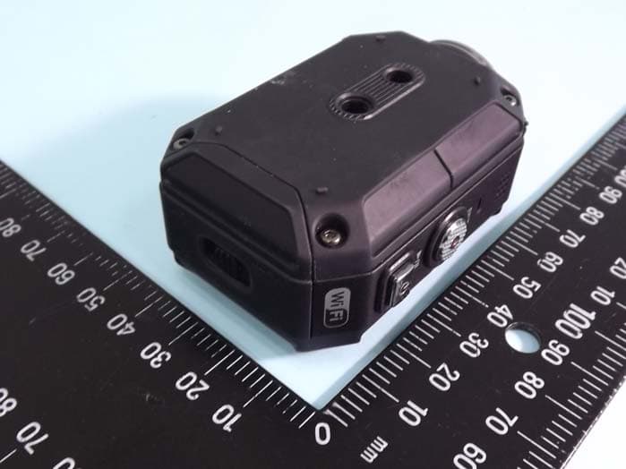
ASIP4C101
Jul 11, 2012Action Camera
Equipment Class
DTS - Digital Transmission System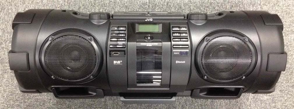
ASIVCB008
Apr 17, 2012POWERED WOOFER CD SYSTEM
Equipment Class
DSS - Part 15 Spread Spectrum Transmitter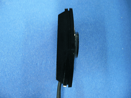
ASIVBA006
Nov 29, 2010Bluetooth audio adaptor for vehicle use.
Equipment Class
DSS - Part 15 Spread Spectrum Transmitter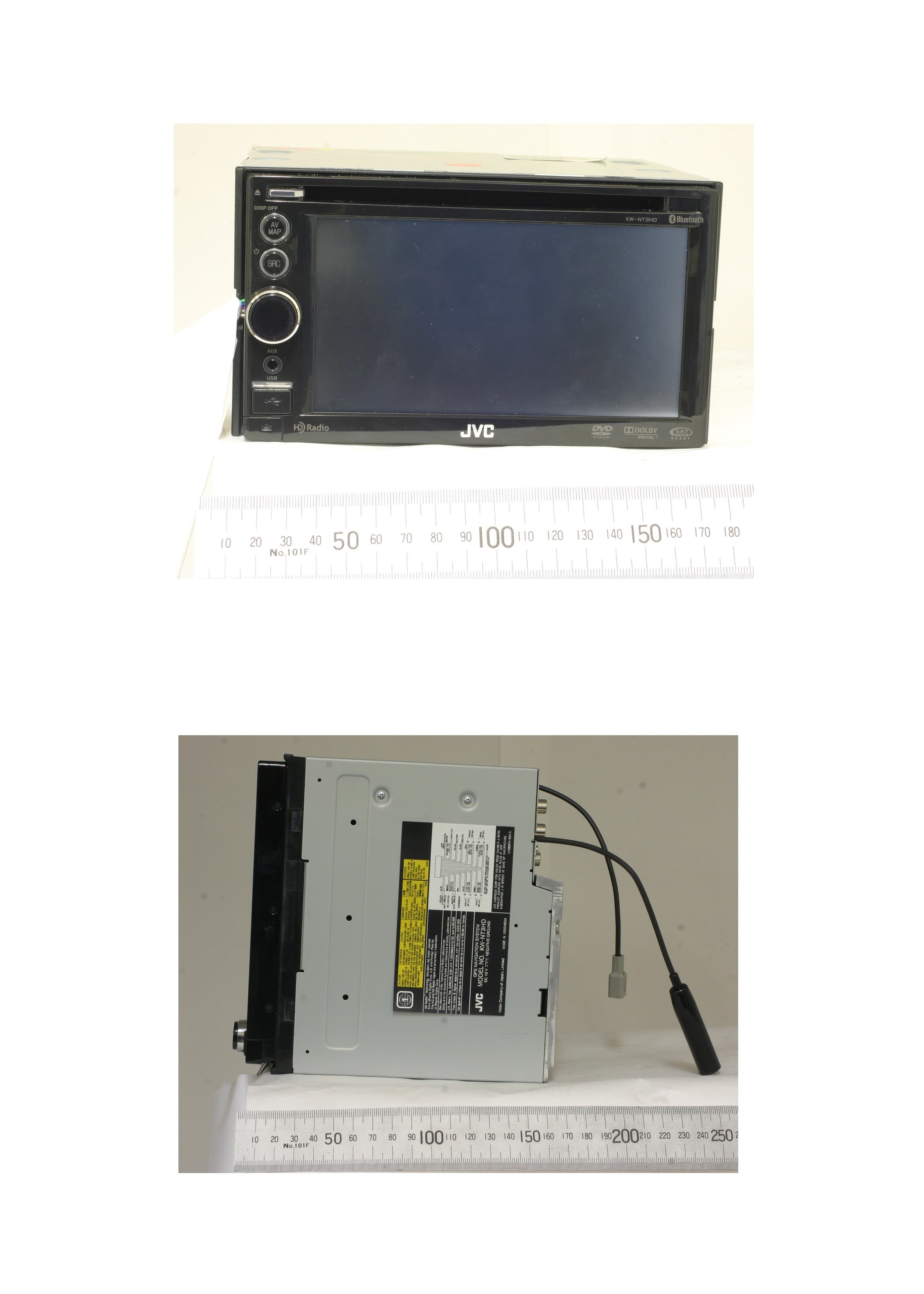
ASIV1A005
Mar 28, 2010GPS Navigation System
Equipment Class
DSS - Part 15 Spread Spectrum Transmitter