ASIVBA006Bluetooth audio adaptor for vehicle use.
JVC KENWOOD Corporation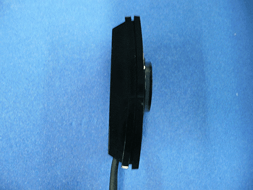
Click to zoom
Application Details
- Equipment Class
- DSS - Part 15 Spread Spectrum Transmitter
- Date of Grant
- Nov 29, 2010
- Application Purpose
- Original Equipment
- Date of Application
- Nov 24, 2010
- Equipment Note
- Bluetooth audio adaptor for vehicle use.
- Frequency Range
- 2402.00000000 - 2480.00000000
- Company
- JVC KENWOOD Corporation
- Country
- Japan
Documents & Files
Document Text
Text extracted from the exhibit documents filed with the FCC. Open a document above to read the original.
Users Manual
INSTRUCTIONS / MANUAL DE INSTRUCCIONES / MANUEL D’INSTRUCTIONS / BEDIENUNGSANLEITUNG / ISTRUZIONI / INSTRUÇÕES LVT2214-002A KS-BTA100 EN, SP, FR, GE, IT, PR © 2010 Victor Company of Japan, Limited For Customer Use: Enter below the Model No. and Serial No. which is located either on the rear or bottom of the speaker unit. Retain this information for future reference. Model No. Serial No. Using the Bluetooth device Warning Stop the car before operating the unit. Caution Operations may be different according to the connected device. Registration of the Bluetooth device Register (pair) a Bluetooth device 1 [Hold this button for 5 seconds.] A play/pause button flashes on and off. 2 Search the KS-BTA100 from your device. 3 If a PIN code is required, enter “0000”. (It is not necessary for some mobile phones.) When registration is completed, a play/pause button lights up. Using the Bluetooth mobile phone Receiving a call When a call comes in... Making a call (Redial) Making a call to the last connected number from your phone. Switching between handsfree and phone While talking... • • • (Low) (High) Microphone Adjusting the microphone volume Volume level: High/ Normal (initial)/ Low [Hold] Ends/rejects call Voice dialing Voice dialing is available only when the connected mobile phone has the voice recognition system. • • Delete all registered devices from the list. • [Hold the two buttons at the same time for about 10 seconds.] Using the Bluetooth audio system [Press] Selects track. [Hold] Fast-forwards or reverses the track. [Press] Play/Pause [Hold] Stop ■ ■ ■ Fig A/Fig A/Fig AFig B/Fig B/Fig B To JVC receiver/ To JVC receiver/ To JVC receiver KS-BTA100 Brown/Brown/Brown Black/Black/Black Blue (white stripe)/ Blue (white stripe)/ Blue (white stripe) Receiver’s Power Cords / Receiver’s Power Cords / Receiver’s Power Cords ENGLISH Thank you for purchasing a JVC product. Installation Warning Avoid installing the adapter unit in the following places. Where they would hinder your safety driving. Where they would be exposed to direct sunlight or heat directly from the heater or placed in an extremely hot place. Where they would be subject to rain, water splashes or excessive humidity. Where they would be subject to dust. Where they would be positioned on an unstable place. Where they could damage the car’s fittings. Where radio wave interferes (EX.: trunk, etc.) Mounting the adapter unit Wipe clean the selected surface sufficiently, and affix the Double-sided tape. (refer to Fig A) Connection (refer to Fig B) – – – – – – – ■ ■ Power cord (Blue,white stripe) / Power cord (Blue,white stripe) / Power cord (Blue,white stripe) / Negative ground / Negative ground / Negative ground Power cord (Brown) / Power cord (Brown) / Power cord (Brown) / ESPAÑOL Thank you for purchasing a JVC product. Installation Warning Avoid installing the adapter unit in the following places. Where they would hinder your safety driving. Where they would be exposed to direct sunlight or heat directly from the heater or placed in an extremely hot place. Where they would be subject to rain, water splashes or excessive humidity. Where they would be subject to dust. Where they would be positioned on an unstable place. Where they could damage the car’s fittings. Where radio wave interferes (EX.: trunk, etc.) Mounting the adapter unit Wipe clean the selected surface sufficiently, and affix the Double-sided tape. (refer to Fig A) Connection (refer to Fig B) – – – – – – – ■ ■ FRANÇAIS Thank you for purchasing a JVC product. Installation Warning Avoid installing the adapter unit in the following places. Where they would hinder your safety driving. Where they would be exposed to direct sunlight or heat directly from the heater or placed in an extremely hot place. Where they would be subject to rain, water splashes or excessive humidity. Where they would be subject to dust. Where they would be positioned on an unstable place. Where they could damage the car’s fittings. Where radio wave interferes (EX.: trunk, etc.) Mounting the adapter unit Wipe clean the selected surface sufficiently, and affix the Double-sided tape. (refer to Fig A) Connection (refer to Fig B) – – – – – – – ■ ■ Fig A/Fig A/Fig AFig B/Fig B/Fig B To JVC receiver/ To JVC receiver/ To JVC receiver KS-BTA100 Brown/Brown/Brown Black/Black/Black Blue (white stripe)/ Blue (white stripe)/ Blue (white stripe) Receiver’s Power Cords / Receiver’s Power Cords / Receiver’s Power Cords DEUTSCH Thank you for purchasing a JVC product. Installation Warning Avoid installing the adapter unit in the following places. Where they would hinder your safety driving. Where they would be exposed to direct sunlight or heat directly from the heater or placed in an extremely hot place. Where they would be subject to rain, water splashes or excessive humidity. Where they would be subject to dust. Where they would be positioned on an unstable place. Where they could damage the car’s fittings. Where radio wave interferes (EX.: trunk, etc.) Mounting the adapter unit Wipe clean the selected surface sufficiently, and affix the Double-sided tape. (refer to Fig A) Connection (refer to Fig B) – – – – – – – ■ ■ Power cord (Blue,white stripe) / Power cord (Blue,white stripe) / Power cord (Blue,white stripe) / Negative ground / Negative ground / Negative ground Power cord (Brown) / Power cord (Brown) / Power cord (Brown) / ITALIANO Thank you for purchasing a JVC product. Installation Warning Avoid installing the adapter unit in the following places. Where they would hinder your safety driving. Where they would be exposed to direct sunlight or heat directly from the heater or placed in an extremely hot place. Where they would be subject to rain, water splashes or excessive humidity. Where they would be subject to dust. Where they would be positioned on an unstable place. Where they could damage the car’s fittings. Where radio wave interferes (EX.: trunk, etc.) Mounting the adapter unit Wipe clean the selected surfac…
Text truncated - open the document above for the full version.
Users Manual
1 Bluetooth Adapter / Adaptador Bluetooth / Adaptateur Bluetooth / Bluetooth-Adapter / Adattatore per Bluetooth / Adaptador de Bluetooth / Bluetooth adapter / Bluetooth-adapter / Bluetooth- adapter / Bluetooth -sovitin / Bluetooth Adaptör / Адаптер Bluetooth / Προσαρμογέας Bluetooth / Adapter Bluetooth / Bluetooth adaptér / Bluetooth Adapter / Bluetooth-адаптер / Adaptor Bluetooth / Bluetooth адаптер / ∫≈Ÿ∑Ÿ∏Õ–·¥Áª‡μÕ√å USB [ ”À√—∫„™È„π À¿“æ¬ÿ‚√ª‡∑Ë“π—Èπ] • ‚≈‚°È·≈–‡§√◊ËÕßÀ¡“¬§”«ò“ Bluetooth ‡ªìπ¢Õß∫√î...í∑ Bluetooth SIG, Inc. ·≈–°“√„™È‡§√◊ËÕßÀ¡“¬¥íß°≈ò“«‚¥¬∫√î...í∑ Victor Company of Japan, Limited (JVC) լ˟¿“¬‰¥È°“√Õπÿ≠“μ„™ô‡§√◊ËÕß À¡“¬°“√§ô“·≈–™ïòÕ∑“ß°“√§È“Õ◊ËπÊ ‡ªìπ î∑∏îú¢ß‡®ô“¢Õ߇§√ïòÕßÀ¡“¬° “√§ô“¥—ß°≈ò“« • Õ–·¥ª‡μÕ√åπ’ȉ¥â√—∫°“√ÕÕ°·∫∫„ÀℙⰗ∫Õÿª°√≥å√—∫ —≠≠“≥„π √∂¬πμå¢Õß JVC ‡∑à“π—Èπ Õ¬à“„™âÕ–·Õª‡μÕ√åπ’È°—∫Õÿª°√≥å√—∫ —≠≠“≥„π√∂¬πμå™π‘¥Õ◊ËπÊ Ì“À√—∫√“¬≈–‡Õ’¬¥Õ◊ËπÊ ‚ª√¥¥Ÿ®“°§Ÿà¡◊Õ∑’Ë®—¥ àß„Àâæ√âÕ¡°—∫‡§√◊ËÕß √—∫ —≠≠“≥¢Õߧÿ≥ ‰∑¬ TH_KS-UBT1.indd 11/19/09 12:43:28 PM / / / / / Adaptor Bluetooth LVT2214-001A [K] EN, SP, FR, GE, IT, PR, NL, SW, DA, FI, TR, RU, GR, PO, CZ, HU, UK, RO, BU, TH, KO, CT, AR, PE, IN KS-BTA100 INSTRUCTIONS MANUAL DE INSTRUCCIONES MANUEL D’INSTRUCTIONS BEDIENUNGSANLEITUNG ISTRUZIONI INSTRUÇÕES GEBRUIKSAANWIJZING BRUKSANVISNING INSTRUKTIONSBOG KÄYTTÖOHJE TALİMATLAR ИНСТРУКЦИИ ПО ЭКСПЛУАТАЦИИ ΟΔΗΓΙΕΣ INSTRUKCJA OBSŁUGI PŘÍRUČKA K OBSLUZE HASZNÁLATI UTASÍTÁSA ІНСТРУКЦІЇ INSTRUCŢIUNI ИНСТРУКЦИИ BUKU PETUNJUK (For CANADA) This device complies with RSS-210 of industry Canada Rules. Operation is subject to the following two conditions: (1) this device may not cause interference, and (2) this device must accept any interference, including interference that may cause undesired operation of the device. Cet appareil est conforme au règlement CNR-210 de l’industrie du Canada. L’utilisation de ce dispositif est autorisée seulement aux conditions suivantes: (1) il ne doit pas produire de brouillage et (2) l’utilisateur du dispositif doit être prêt à accepter tout brouillage radioélectrique reçu, même si ce brouillage est susceptible de compromettre le fonctionnement du dispositif. (For USA) CAUTION: This device and its antenna(s) must not be co-located or operating in conjunction with any other antenna or transmitter. End user cannot modify this transmitter device. Any unauthorized modification made on the device could avoid the user’s authority to operate this device. (For Canada) “The installer of this radio equipment must ensure that the antenna is located or pointed such that it does not emit RF field in excess of Health Canada limits for the general population, consult Safety Code 6, obtainable from Health Canada’s website www. hc-sc.gc.ca/rpb” The countries where you may use the Bluetooth® function ع ع ع ع ع ع ع ع ع ع ع ع ع ع ع ع ع ع ع ع ع ع ع ع ع ع ع ع ع ع ع Die Länder, in denen Sie die Bluetooth® Funktion verwenden können Pays où vous pouvez utiliser la fonction Bluetooth® De landen waar u de Bluetooth®-functie mag gebruiken Países en los que se puede utilizar la función Bluetooth® Paesi nei quali è possibile utilizzare la funzione Bluetooth® Länder där du kan använda Bluetooth®-funktionen Lande, hvor du kan bruge Bluetooth®-funktionen Land hvor du kan bruke Bluetooth®-funksjonen Maat, joissa voi käyttää Bluetooth®-toimintoa Países onde pode usar a função Bluetooth® Země, ve kterých můžete využívat funkci Bluetooth® Azok az országok, amelyekben használhatjuk a Bluetooth®-funkciót Kraje, w których można używać funkcji Bluetooth® Države, kjer lahko uporabljate funkcijo Bluetooth® Krajiny, v ktorých môžete využívať funkciu Bluetooth® Valstis, kur jūs varat izmantot Bluetooth® funkciju Šalys, kuriose galite naudotis „Bluetooth®“ funkcija Il-pajjiżi fejn tista’ tuża l-funzjoni Bluetooth® Lönd þar sem hægt er að nota Bluetooth® Riigid, kus on võimalik kasutada Bluetooth® funktsiooni Bluetooth® fonksiyonunu kullanabileceğiniz ülkeler Na tíortha inar féidir leat feidhmiú Bluetooth® a úsáid Länner an denen der d’Bluetooth® Funktioun benotze kënnt. Els països on podrà fer servir la funció Bluetooth® Zemlje u kojima je dozvoljena upotreba Bluetooth® funkcije. Zemlje u kojima možete koristiti Bluetooth® funkciju Zemlje u kojima je dopušteno koristiti Bluetooth®. Земји каде можете да ја користите функцијата Bluetooth® Страните, в които можете да ползвате функцията Bluetooth® Ţările în care puteţi utiliza funcţia Bluetooth® ع Οι χώρες όπου μπορείτε να χρησιμοποιήσετε τη λειτουργία Bluetooth® Country Andorra Australia Österreich Bosna i Hercegovina Belgien Belgique България Canada Schweiz Suisse Κύπρος Kıbrıs Česká republika Deutschland Danmark Eesti España Suomi Finland France United Kingdom Ελλάδα Hrvatska Magyarország Ireland Éire Ísland Italia Lichtenstein Lietuva Country Luxemburg Luxembourg Lëtzebuerg Latvija Monaco Crna Gora Македонија Malta Nederland Norge New Zealand Polska Portugal România Srbija Sverige Slovenija Slovensko Türkiye United States of America 2 Declaration of Conformity with regard to the R&TTE Directive 1999/5/EC 0197 INFORMATION (For U.S.A.) This equipment has been tested and found to comply with the limits for a Class B digital device, pursuant to Part 15 of the FCC Rules. These limits are designed to provide reasonable protection against harmful interference in a residential installation. This equipment generates, uses, and can radiate radio frequency energy and, if not installed and used in accordance with the instructions, may cause harmful interference to radio communications. However, there is no guarantee that interference will not occur in a particular installation. If this equipment does cause harmful interference to radio or television reception, which can be determined by turning the equipment off and on, the user is encouraged to try to correct the interference by one or more of the following measures: – Reorient or relocate the receiving antenna. – Increase the separation between the equipment and receiver. – Connect the equipment into an outlet on…
Text truncated - open the document above for the full version.
External Photos
Photographs of KS-BTA100 [External photos] <Front view> <Rear View> <Side view –Left side> <Side view –Right side> <Top view> <Bottom view>
ID Label/Location Info
Label information ・Appearance of Label Label-A Label-B Position of label Label-A is located backside of bottom enclosure
Internal Photos
[Internal photos] <Top side of PCB> <Back side of PCB>
RF Exposure Info
FCC ID: ASIVBA006 IC: 2320A-VBA006 Produkte Products RF Exposure Statement: 12607877 002 Page 1 of 1 Client: Victor Company of Japan Ltd 3-12, Moriya-cho,Kanagawa-ku ,Yokohama 221, Japan Test item: Bluetooth Adaptor Identification: KS-BTA100 FCC Requirement According to KDB 447498, SAR evaluation specified in FCC 2.1093 is not required for portable equipment if the transmitter power is below the following threshold: Tunable Range Lowest Frequency [GHz] Highest Frequency [GHz] Center of Tunable Band [GHz] 60/f SAR Limitation based on Center of Band [mW] 2.402 2.480 2.441 24.58 IC Requirement According to RSS-102 (Issue 4), clause 2.5.1, no SAR evaluation is required if the transmitter power (both conducted and e.i.r.p.) is below the following threshold: Equipment Use Frequency Range SAR Limitation [mW] General Public Use 2.2 – 3GHz 20 Measurement Result The maximum measured transmitter power is the following: Conducted Output Power P out [mW] Maximum Antenna Gain [dBi] P out EIRP [mW] 3.26 0.73 3.86 Conclusion SAR evaluation is not required since the maximum transmitter power P out (both conducted and e.i.r.p.) is below the FCC and IC thresholds. Refer to test report 12607877 001 for more details. TÜV Rheinland Japan Ltd. - Global Technology Assessment Center 4-25-2 Kita-Yamata, Tsuzuki-ku, Yokohama 224-0021, Japan
Test Report
FCC ID: ASIVBA006 IC: 2320A-VBA006 Produkte Products Prüfbericht - Nr.: Test Report No.: 12607877 001 Seite 2 von 76 Page 2 of 76 TEST SUMMARY 3.2.1 VOLTAGE REQUIREMENTS, FCC 15.31(E) RESULT: PASS 3.2.2 ANTENNA REQUIREMENTS, FCC 15.203, FCC 15.204 AND RSS-GEN 7.1.4 RESULT: PASS 5.1.1 C ONDUCTED OUTPUT POWER, FCC 15.247(B)(1) AND RSS-210 A8.4(2) RESULT: PASS 5.1.2 C ARRIER FREQUENCY SEPARATION, FCC 15.247(A)(1) AND RSS-210 A8.1(B) RESULT: PASS 5.1.3 20 DB BANDWIDTH, FCC 15.247(A)(1) AND RSS-210 A8.1(A) 5.1.4 99% BANDWIDTH, RSS-GEN 4.6.1 5.1.5 NUMBER OF HOPPING FREQUENCIES, FCC 15.247(A)(1)(III) AND RSS-210 A8.1(D) RESULT: PASS 5.1.6 AVERAGE TIME OF OCCUPANCY, FCC 15.247(A)(1)(III) AND RSS-210 A8.1(D) RESULT: PASS 5.1.7 CONDUCTED SPURIOUS EMISSION, FCC 15.247(D) AND RSS-210 A8.5 RESULT: PASS 6.1.1 BAND EDGE RADIATED EMISSION, FCC 15.205, FCC 15.209, FCC 15.247(D), RSS-210 2.2, RSS-210 2.6 AND RSS-210 A8.5 RESULT: Pass 6.1.2 RADIATED SPURIOUS EMISSION OF TRANSMITTER, FCC 15.205, FCC 15.209, FCC 15.247(D), RSS-210 2.2, RSS-210 2.6 AND RSS-210 A8.5 RESULT: PASS 6.2.1 RADIATED SPURIOUS EMISSION OF RECEIVER, FCC 15.109, RSS-210 2.2, RSS- 210 2.6, RSS-210 A8.5, RSS-GEN 7.2.3.2 RESULT: PASS 7.1.1 AC POWER LINE CONDUCTED EMISSION OF TRANSMITTER, FCC 15.207 AND RSS- GEN 7.2.2 RESULT: N/A 7.2.1 AC POWER LINE CONDUCTED EMISSION OF RECEIVER, FCC 15.107 AND RSS-GEN 7.2.2 RESULT: N/A FCC ID: ASIVBA006 IC: 2320A-VBA006 Produkte Products Prüfbericht - Nr.: Test Report No.: 12607877 001 Seite 3 von 76 Page 3 of 76 Contents 1. GENERAL REMARKS............................................................................................... 5 1.1 COMPLEMENTARY MATERIALS................................................................................. 5 2. TEST SITES............................................................................................................ 5 2.1 T EST FACILITIES..................................................................................................... 5 2.2 LIST OF TEST AND MEASUREMENT INSTRUMENTS...................................................... 6 2.3 M EASUREMENT UNCERTAINTY................................................................................. 7 3. GENERAL PRODUCT INFORMATION........................................................................... 8 3.1 PRODUCT FUNCTION AND INTENDED USE.................................................................. 8 3.2 S YSTEM DETAILS.................................................................................................... 8 3.2.1 Voltage Requirements, FCC 15.31(e)..........................................................................................9 3.2.2 Antenna Requirements, FCC 15.203, FCC 15.204 and RSS-Gen 7.1.4.....................................9 3.3 INDEPENDENT OPERATION MODES........................................................................... 9 3.4 CLOCK FREQUENCIES........................................................................................... 10 3.5 NOISE SUPPRESSING PARTS.................................................................................. 10 4. TEST SET-UP AND OPERATION MODES................................................................... 11 4.1 T EST METHODOLOGY............................................................................................ 11 4.2 PHYSICAL CONFIGURATION FOR TESTING............................................................... 11 4.3 TEST OPERATION AND TEST SOFTWARE................................................................. 12 4.4 S PECIAL ACCESSORIES AND AUXILIARY EQUIPMENT............................................... 13 4.5 COUNTERMEASURES TO ACHIEVE EMC COMPLIANCE.............................................. 13 5. T EST RESULTS OF CONDUCTED MEASUREMENTS AT ANTENNA PORT....................... 14 5.1 T RANSMITTER PARAMETERS.................................................................................. 14 5.1.1 Conducted Output Power, FCC 15.247(b)(1) and RSS-210 A8.4(2).........................................14 5.1.2 Carrier Frequency Separation, FCC 15.247(a)(1) and RSS-210 A8.1(b)..................................17 5.1.3 20dB Bandwidth, FCC 15.247(a)(1) and RSS-210 A8.1(a) .......................................................20 5.1.4 99% Bandwidth, RSS-Gen 4.6.1................................................................................................25 5.1.5 Number of Hopping Frequencies, FCC 15.247(a)(1)(iii) and RSS-210 A8.1(d) ........................30 5.1.6 Average Time of Occupancy, FCC 15.247(a)(1)(iii) and RSS-210 A8.1(d)...............................33 5.1.7 Conducted Spurious Emission, FCC 15.247(d) and RSS-210 A8.5..........................................36 6. TEST RESULTS OF RADIATED MEASUREMENTS....................................................... 58 6.1 T RANSMITTER PARAMETERS.................................................................................. 58 6.1.1 Band Edge Radiated Emission, FCC 15.205, FCC 15.209, FCC 15.247(d), RSS-210 2.2, RSS-210 2.6 and RSS-210 A8.5 ...............................................................................................58 6.1.2 Radiated Spurious Emission of Transmitter, FCC 15.205, FCC 15.209, FCC 15.247(d), RSS-210 2.2, RSS-210 2.6 and RSS-210 A8.5.........................................................................63 FCC ID: ASIVBA006 IC: 2320A-VBA006 Produkte Products Prüfbericht - Nr.: Test Report No.: 12607877 001 Seite 4 von 76 Page 4 of 76 6.2 RECEIVER PARAMETERS....................................................................................... 66 6.2.1 Radiated Spurious Emission of Receiver, FCC 15.109, RSS-210 2.2, RSS-210 2.6, RSS- 210 A8.5, RSS-Gen 7.2.3.2 .......................................................................................................66 7. TEST RESULTS OF AC POWER LINE CONDUCTED MEASUREMENTS.......................... 68 7.1 T RANSMITTER PARAMETERS............................................…
Text truncated - open the document above for the full version.
Test Setup Photos
FCC ID: ASIVBA006 IC: 2320A-VBA006 Produkte Products Prüfbericht - Nr.: Test Report No.: 12607877 001 Seite 69 von 76 Page 69 of 76 8. Photographs of the Test Setup Photograph 1: Set-up for Conducted Emissions at Antenna Port FCC ID: ASIVBA006 IC: 2320A-VBA006 Produkte Products Prüfbericht - Nr.: Test Report No.: 12607877 001 Seite 70 von 76 Page 70 of 76 Photograph 2: Set-up for Radiated Emission of Transmitter, Front View Photograph 3: Set-up for Radiated Emission of Transmitter, Rear View FCC ID: ASIVBA006 IC: 2320A-VBA006 Produkte Products Prüfbericht - Nr.: Test Report No.: 12607877 001 Seite 71 von 76 Page 71 of 76 Photograph 4: Set-up for Radiated Emission of Receiver, Front View Photograph 5: Set-up for Radiated Emission of Receiver, Rear View FCC ID: ASIVBA006 IC: 2320A-VBA006 Produkte Products Prüfbericht - Nr.: Test Report No.: 12607877 001 Seite 72 von 76 Page 72 of 76 Photograph 6: Set-up for Radiated Emission, EUT Configuration X-Axis Photograph 7: Set-up for Radiated Emission, EUT Configuration Y-Axis FCC ID: ASIVBA006 IC: 2320A-VBA006 Produkte Products Prüfbericht - Nr.: Test Report No.: 12607877 001 Seite 73 von 76 Page 73 of 76 Photograph 8: Set-up for Radiated Emission, EUT Configuration Z-Axis
Contact Information
Applicant
Yasukazu Katakai(Manager)
Test Firm
TUV Rheinland Japan Ltd.Thimo Sauter
Technical Specifications
| # | Rule Parts | Frequency Range | Power Output |
|---|---|---|---|
| 1 | 15C | 2.40 GHz - 2.48 GHz | 3.26 mW |
Other Applications from JVC KENWOOD Corporation

ASIZWSA1
Jul 27, 2020SMART HEADSETS
Equipment Class
DSS - Part 15 Spread Spectrum Transmitter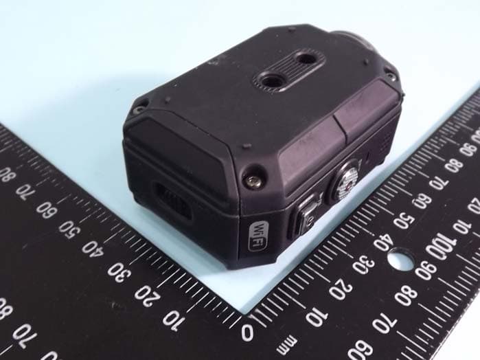
ASIP4C101
Jul 11, 2012Action Camera
Equipment Class
DTS - Digital Transmission System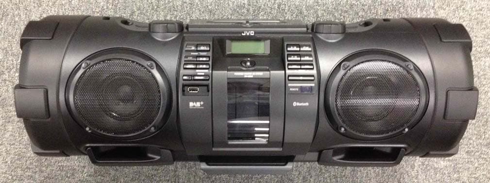
ASIVCB008
Apr 17, 2012POWERED WOOFER CD SYSTEM
Equipment Class
DSS - Part 15 Spread Spectrum Transmitter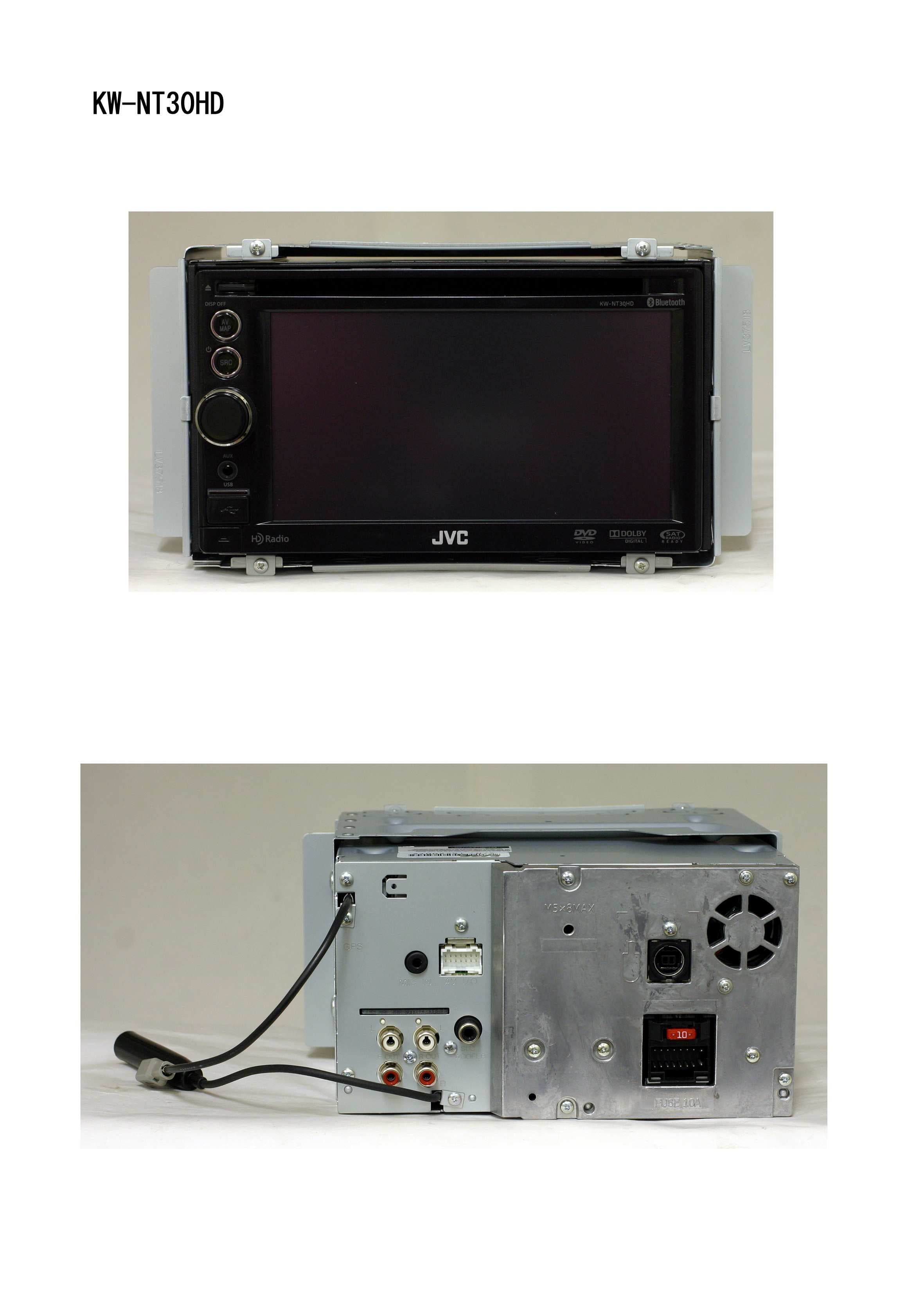
ASIV1B007
Jan 31, 2011GPS Navigation System
Equipment Class
DSS - Part 15 Spread Spectrum Transmitter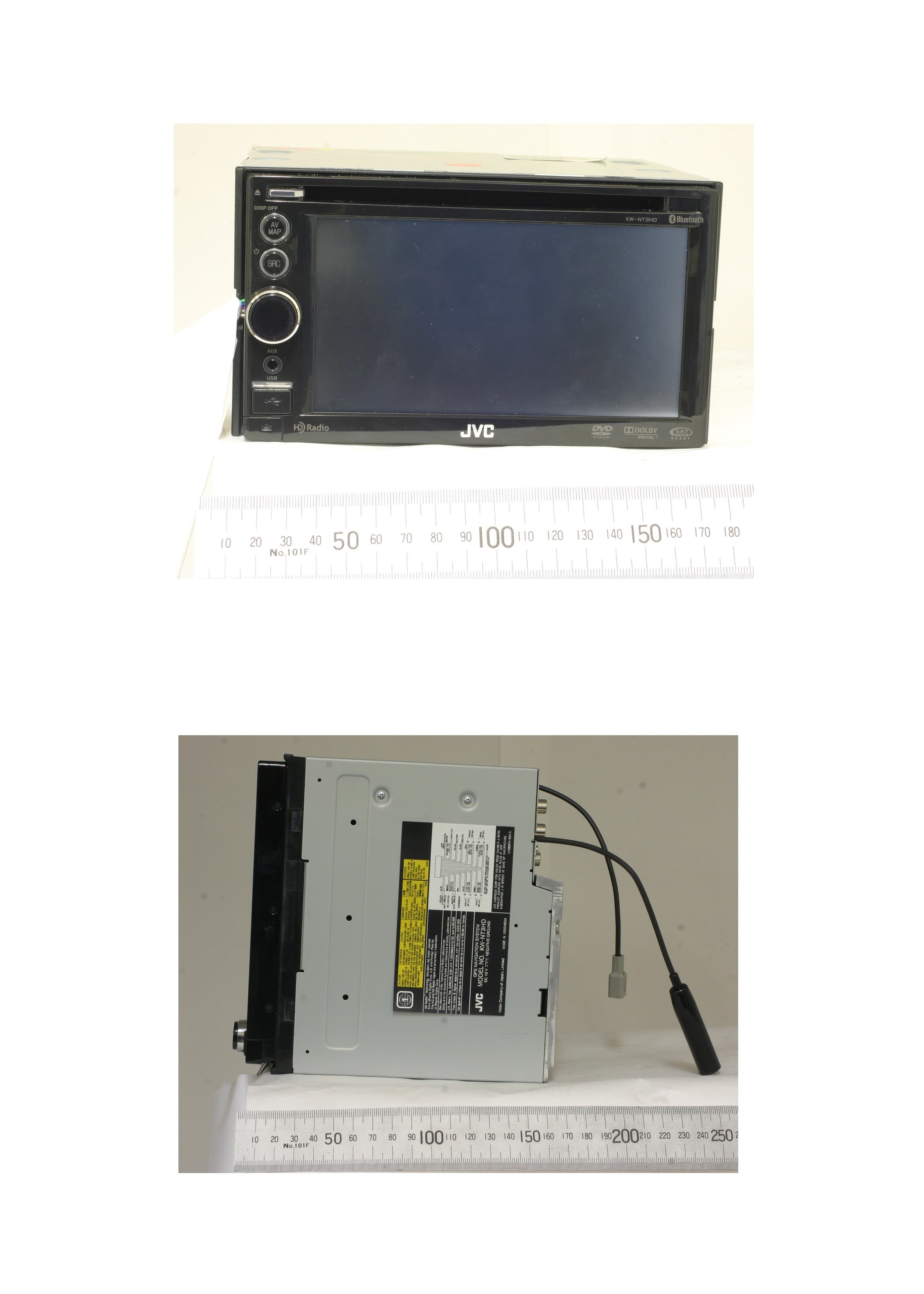
ASIV1A005
Mar 28, 2010GPS Navigation System
Equipment Class
DSS - Part 15 Spread Spectrum Transmitter