ASIV1U001Wireless Transmitter
JVC KENWOOD Corporation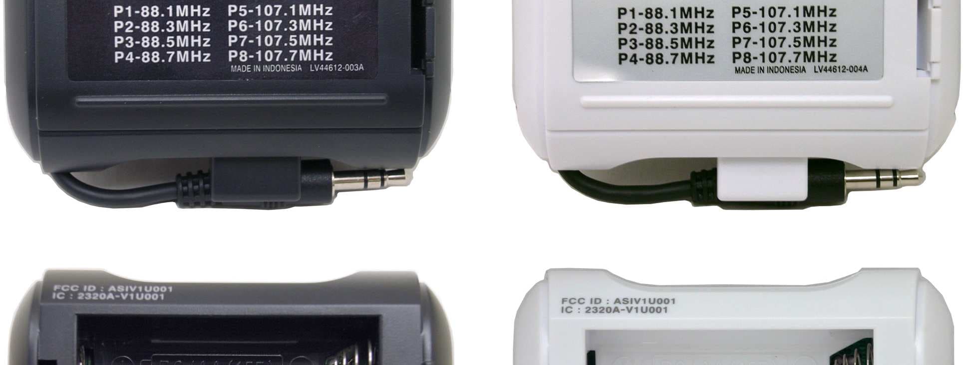
Click to zoom
Application Details
- Equipment Class
- DXX - Part 15 Low Power Communication Device Transmitter
- Date of Grant
- Feb 15, 2006
- Application Purpose
- Original Equipment
- Date of Application
- Feb 15, 2006
- Equipment Note
- Wireless Transmitter
- Frequency Range
- 88.00000000 - 108.00000000
- Company
- JVC KENWOOD Corporation
- Country
- Japan
Documents & Files
Document Text
Text extracted from the exhibit documents filed with the FCC. Open a document above to read the original.
Users Manual
Victor Company of Japan, Limited Victor Company of Japan, LimitedVictor Company of Japan, Limited Victor Company of Japan, Limited G-1 Warnings, Cautions and Others Mises en garde, précautions et indications diverses The lightning flash with arrowhead symbol, within an equilateral triangle is intended to alert the user to the presence of uninsulated “dangerous voltage” within the product’s enclosure that may be of sufficient magnitude to constitute a risk of electric shock to persons. The exclamation point within an equilateral triangle is intended to alert the user to the presence of important operating and maintenance (servicing) instructions in the literature accompanying the appliance. CAUTION — ON/STANDBY button! Disconnect the mains plug to shut the power off completely (the STANDBY lamp goes off). When installing the apparatus, ensure that the plug is easily accessible. The ON/STANDBY button in any position does not disconnect the mains line. • When the unit is on standby, the STANDBY lamp lights red. • When the unit is turned on, the STANDBY lamp goes off. The power can be remote controlled. ATTENTION — Touche ON/STANDBY! Déconnectez la fiche secteur pour mettre l’appareil complètement hors tension (le témoin STANDBY l s’éteint). Lors de l’installation de l’appareil, assurez-vous que la fiche soit facilement accessible. La touche ON/STANDBY dans n’importe quelle position ne déconnecte pas l’appareil du secteur. • Quand l’appareil est en mode d’attente, le témoin STANDBY est allumé en rouge. • Quand l’appareil est sous tension, le témoin STANDBY s’éteint. L’alimentation ne peut pas être commandée à distance. CAUTION To reduce the risk of electrical shocks, fire, etc.: 1. Do not remove screws, covers or cabinet. 2. Do not expose this appliance to rain or moisture. ATTENTION Afin d’éviter tout risque d’électrocution, d’incendie, etc.: 1. Ne pas enlever les vis ni les panneaux et ne pas ouvrir le coffret de l’appareil. 2. Ne pas exposer l’appareil à la pluie ni à l’humidité. For U.S.A. This equipment has been tested and found to comply with the limits for a Class B digital device, pursuant to part 15 of the FCC Rules. These limits are designed to provide reasonable protection against harmful interference in a residential installation. This equipment generates, uses, and can radiate radio frequency energy and, if not installed and used in accordance with the instructions, may cause harmful interference to radio communications. However, there is no guarantee that interference will not occur in a particular installation. If this equipment does cause harmful interference to radio or television reception, which can be determined by turning the equipment off and on, the user is encouraged to try to correct the interference by one of the following measures: Reorient or relocate the receiving antenna. Increase the separation between the equipment and receiver. Connect the equipment into an outlet on a circuit different from that to which the receiver is connected. Consult the dealer or an experienced radio/TV technician for help. For wireless transmitter This device complies with Part 15 of the FCC Rules. Operation is subject to the following two conditions: (1) This device may not cause harmful interference. (2) This device must accept any interference received, including interference that may cause undesired operation. IMPORTANT NOTE: FCC Radiation Exposure Statement: This equipment complies with FCC RF radiation exposure limits set forth for an uncontrolled environment. To maintain compliance with FCC RF exposure compliance requirements, please avoid direct contact to the transmitting antenna during transmitting. This transmitter must not be co-located or operating in conjunction with any other antenna or transmitter. For Canada/pour le Canada THIS DIGITAL APPARATUS DOES NOT EXCEED THE CLASS B LIMITS FOR RADIO NOISE EMISSIONS FROM DIGITAL APPARATUS AS SET OUT IN THE INTERFERENCE-CAUSING EQUIPMENT STANDARD ENTITLED “DIGITAL APPARATUS,” ICES-003 OF THE DEPARTMENT OF COMMUNICATIONS. CET APPAREIL NUMERIQUE RESPECTE LES LIMITES DE BRUITS RADIOELECTRIQUES APPLICABLES AUX APPAREILS NUMERIQUES DE CLASSE B PRESCRITES DANS LA NORME SUR LE MATERIEL BROUILLEUR: “APPAREILS NUMERIQUES”, NMB-003 EDICTEE PAR LE MINISTRE DES COMMUNICATIONS. Operation is subject to the following two conditions: (1) this device may not cause interference, and (2) this device must accept any interference, including interference that may cause undesired operation of the device. L’utilisation de ce dispositif est autorisée seulement aux conditions suivantes : (1) il ne doit pas produire de brouillage et (2) l’utilisateur du dispositif doit être prêt à accepter tout brouillage radioélectrique reçu, même si ce brouillage est susceptible de compromettre le fonctionnement du dispositif. Caution_RV-NB10[J]f.fm Page 1 Friday, January 20, 2006 4:58 PM Wireless (FM) Transmitter Model: VFT-001/VFT-001W User's Manual 1 / 9 Victor Company of Japan, Limited Victor Company of Japan, LimitedVictor Company of Japan, Limited Victor Company of Japan, Limited G-2 IMPORTANT FOR LASER PRODUCTS 1. CLASS 1 LASER PRODUCT 2. CAUTION: Do not open the top cover. There are no user serviceable parts inside the unit; leave all servicing to qualified service personnel. 3. CAUTION: Visible and/or invisible class 1M laser radiation when open. Do not view directry with optical instruments. IMPORTANT POUR PRODUITS LASER 1. PRODUIT LASER CLASSE 1 2. ATTENTION: N’ouvrez pas le couvercle supérieur. Il n’y a aucune pièce réparable par l’utilisateur à l’intérieur de l’appareil; confiez toute réparation à un personnel qualifié. 3. ATTENTION: Rayonnement laser visible et/ou invisible de classe 1M une fois ouvert. Ne pas regarder directement avec des instruments optiques. CAUTION: •Do not block the ventilation openings or holes. (If the ventilation openings or holes are blocked by a newspaper or cloth, etc., the heat may not be able to get out. •Do not place any naked…
Text truncated - open the document above for the full version.
Block Diagram
Victor Company of Japan, Limited Victor Company of Japan, LimitedVictor Company of Japan, Limited Victor Company of Japan, Limited Wireless (FM) Transmitter Model: VFT-001/VFT-001W Block Diagram Block DiagramBlock Diagram Block Diagram February, 2006 Victor Company of Japan, Limited 10-1,Ohwatari-machi 1-chome Maebashi, Gunma-ken 371-8543 JAPAN
External Photos
Victor Company of Japan, Limited Victor Company of Japan, LimitedVictor Company of Japan, Limited Victor Company of Japan, Limited Wireless (FM) Transmitter Model: VFT-001/VFT-001W February, 2006 Victor Company of Japan, Limited 10-1,Ohwatari-machi 1-chome Maebashi, Gunma-ken 371-8543 JAPAN
ID Label/Location Info
Victor Company of Japan, Limited Victor Company of Japan, LimitedVictor Company of Japan, Limited Victor Company of Japan, Limited Wireless (FM) Transmitter Model: VFT-001/VFT-001W Victor Company of Japan, Limited 10-1,Ohwatari-machi 1-chome Maebashi, Gunma-ken 371-8543 JAPAN February, 2006
Internal Photos
Victor Company of Japan, Limited Victor Company of Japan, LimitedVictor Company of Japan, Limited Victor Company of Japan, Limited Wireless (FM) Transmitter Model: VFT-001/VFT-001W February, 2006 Victor Company of Japan, Limited 10-1,Ohwatari-machi 1-chome Maebashi, Gunma-ken 371-8543 JAPAN
Internal Photos
Victor Company of Japan, Limited Victor Company of Japan, LimitedVictor Company of Japan, Limited Victor Company of Japan, Limited Wireless (FM) Transmitter Model: VFT-001/VFT-001W February, 2006 Victor Company of Japan, Limited 10-1,Ohwatari-machi 1-chome Maebashi, Gunma-ken 371-8543 JAPAN
Test Report
TEST REPORT Report No. :5166F-B-2 Page : 2 of 35 Table of Contents 1 TEST REPORT .........................................................................................................................................................................3 2 GENERAL INFORMATION ......................................................................................................................................................3 2.1 P RODUCT DESCRIPTION.......................................................................................................................................................3 2.2 S UMMARY OF TEST AND INSPECTION RESULT........................................................................................................................4 2.3 T EST METHODOLOGY...........................................................................................................................................................4 2.4 T EST FACILITY.....................................................................................................................................................................4 3 SYSTEM TEST CONFIGURATION ..........................................................................................................................................4 3.1 J USTIFICATION.....................................................................................................................................................................4 3.2 O PERATING MODES..............................................................................................................................................................5 3.3 L IST OF ACCESSORIES..........................................................................................................................................................5 3.4 I NTERFACE CABLES.............................................................................................................................................................5 3.5 S PECIAL TEST CONDITION....................................................................................................................................................5 3.6 E QUIPMENT MODIFICATIONS.................................................................................................................................................5 3.7 C ONFIGURATION OF TESTED SYSTEM...................................................................................................................................6 3.8 P OWER SUPPLY TO EUT......................................................................................................................................................6 4 ANTENNA REQUIREMENT .....................................................................................................................................................7 5 AC CONDUCTED EMISSION TEST ........................................................................................................................................8 6 RADIATED EMISSION TEST ...................................................................................................................................................9 6.1 T EST SETUP........................................................................................................................................................................9 6.2 T EST INSTRUMENTATION....................................................................................................................................................10 6.3 R ADIATED EMISSION CALCULATION.....................................................................................................................................11 6.4 T EST RESULTS..................................................................................................................................................................12 6.4.1 Field Strength of Fundamental Emissions .......................................................................................................12 6.4.2 20dB Bandwidth ..............................................................................................................................................13 6.4.3 Radiated Emission...........................................................................................................................................14 7 E.I.R.P. CALCULATION FROM FIELD STRENGTH OF FUNDAMENTAL EMISSIONS......................................................21 8 PHOTOS OF TESTED EUT....................................................................................................................................................22 8.1 E XTERNAL PHOTOS...........................................................................................................................................................22 9 PHOTOS OF TEST SETUP ....................................................................................................................................................23 9.1 P HOTOS OF RADIATED MEASUREMENT...............................................................................................................................23 APPENDIX 1 CERTIFICATE OF NVLAP ACCREDITATION ....................................................................................................26 APPENDIX 2 THE UNWANTED EMISSIONS IN ADJACENT CARRIER FREQUENCY AREA ..............................................27 APPENDIX 3 CONVERSION FROM FIELD STRENGTH TO E.I.R.P........................................................................................35 TEST REPORT Report No. :5166F-B-2 Page : 3 of 35 1 Test report (1) This report summarizes the result of a single investigation and test result relate only to tested sample. (2) The report shall not be reproduced except in full without the written approval of the Taiyo Yuden Co.,Ltd. (3) This test report must not be used by the client to claim pr…
Text truncated - open the document above for the full version.
Test Setup Photos
JVC Wireless Transmitter VFT-001 TEST SET UP PHOTO 1. Photos of Radiated Measurement Axial Direction : XY-Plane JVC Wireless Transmitter VFT-001 Axial Direction : YZ-Plane JVC Wireless Transmitter VFT-001 Axial Direction : ZX-Plane
Contact Information
Applicant
Yasukazu Katakai(Manager)
Technical Contact
Taiyo Yuden Co., Ltd.Kenzo Furuta
[email protected]+81 27360 8328
5607-2 Nakamuroda Harunamachi · Gunma-Gun Gunma · Japan
Test Firm
Taiyo Yuden Co., Ltd. EMC CenterKenzo Furuta
Technical Specifications
| # | Rule Parts | Frequency Range | Power Output |
|---|---|---|---|
| 1 | 15C | 88 MHz - 108 MHz | - |
Other Applications from JVC KENWOOD Corporation

ASIZWSA1
Jul 27, 2020SMART HEADSETS
Equipment Class
DSS - Part 15 Spread Spectrum Transmitter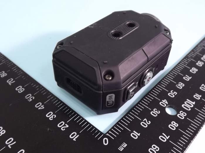
ASIP4C101
Jul 11, 2012Action Camera
Equipment Class
DTS - Digital Transmission System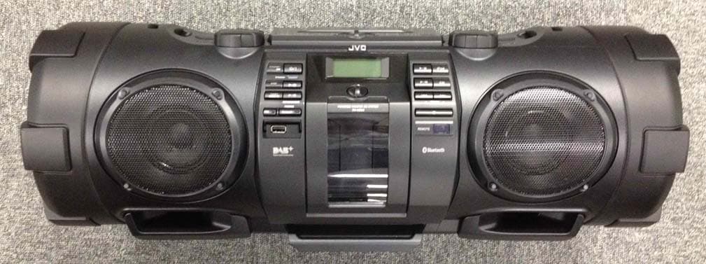
ASIVCB008
Apr 17, 2012POWERED WOOFER CD SYSTEM
Equipment Class
DSS - Part 15 Spread Spectrum Transmitter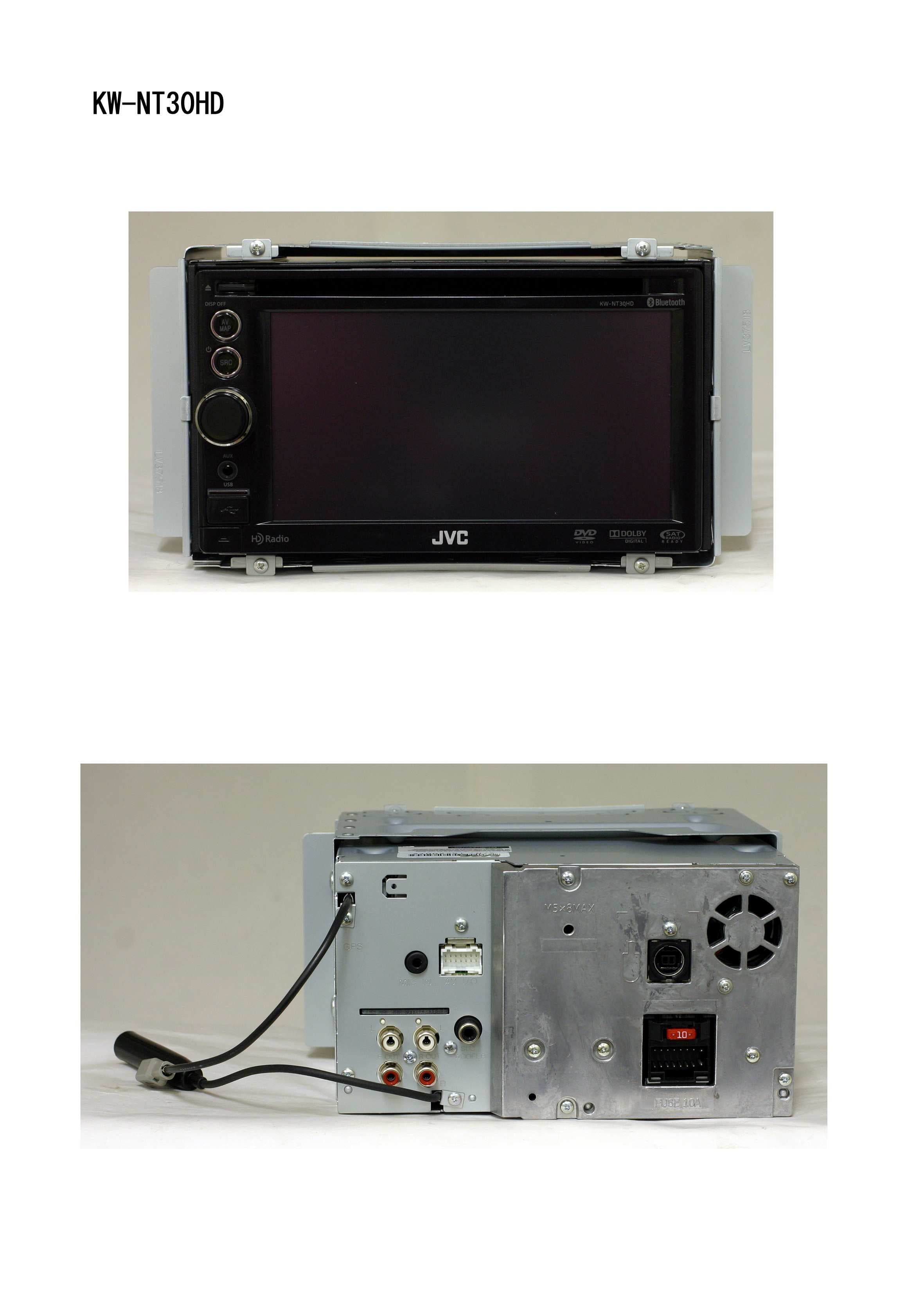
ASIV1B007
Jan 31, 2011GPS Navigation System
Equipment Class
DSS - Part 15 Spread Spectrum Transmitter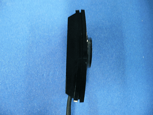
ASIVBA006
Nov 29, 2010Bluetooth audio adaptor for vehicle use.
Equipment Class
DSS - Part 15 Spread Spectrum Transmitter