ASIV7V002Bluetooth Car Entertainment System Module
JVC KENWOOD Corporation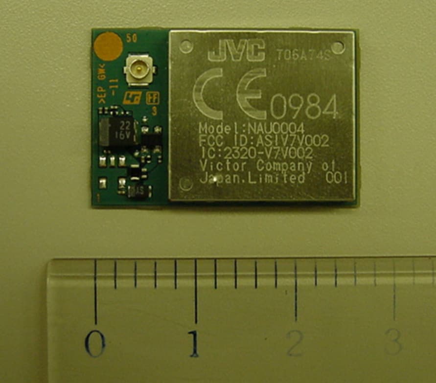
Click to zoom
Application Details
- Equipment Class
- DSS - Part 15 Spread Spectrum Transmitter
- Date of Grant
- Oct 08, 2007
- Application Purpose
- Original Equipment
- Date of Application
- Oct 08, 2007
- Equipment Note
- Bluetooth Car Entertainment System Module
- Frequency Range
- 2402.00000000 - 2480.00000000
- Company
- JVC KENWOOD Corporation
- Country
- Japan
Documents & Files
Document Text
Text extracted from the exhibit documents filed with the FCC. Open a document above to read the original.
Users Manual
NAU0004Manual Description The NAU0004 is a fully integrated Class 2 radio and baseband module conforming to ver. 1.2 and ver 2.0 of the Bluetooth specification. It contains the DSP, co-processor supporting enhanced audio applications. The NAU0004 is the Bluetooth module for Car Entertainment System. Features Audio In/Out, PCM, UART, SPI, PIO, AIO interfaces, enabling a wide range of applications. 8M-bit on-module flash memory Voltage regulator : internal 1.8V regulator Based on the Bluecore3-Multimedia External from CSR Channel quality driven data rate General Specifications [Module] Antenna connector impedance: 50Ω External interfaces: Audio In/Out, PCM, UART, PIO, AIO Supply voltage: 2.90 to 3.60 V Package dimensions: 27 18 3.2mm [Antenna] Pattern Antenna Coaxial connector mounted PCB dimensions: 28 8 1.6mm 28mm 8mm 1.6mm 28mm 8mm 1.6mm [Antenna cable] Two Coaxial connectors Specifications Item Specifications Frequency 2402 to 2480 MHz Modulation FHSS / GFSK Channel intervals 1MHz Number of channels 79CH Output power(Average) +4dBm(max) FCC Regulatory Information This equipment has been tested and found to comply with the limits for a Class B digital device, pursuant to part 15 of the FCC Rules. These limits are designed to provide reasonable protection against harmful interference in a residential installation. This equipment generates, uses and can radiate radio frequency energy and, if not installed and used in accordance with the instructions, may cause harmful interference to radio communications. However, there is no guarantee that interference will not occur in a particular installation. If this equipment does cause harmful interference to radio or television reception, which can be determined by turning the equipment off and on, the user is encouraged to try to correct the interference by one or more of the following measures: - Reorient or relocate the receiving antenna. - Increase the separation between the equipment and receiver. - Connect the equipment into an outlet on a circuit different from that to which the receiver is connected. - Consult the dealer or an experienced radio/TV technician for help. FCC WARNING: Change or modifications not expressly approved by the party responsible for compliance could void the user’s authority to operate the equipment. RF exposure compliance This module has very low levels of RF energy that it deemed to comply without maximum permissive exposure evaluation (MPE). But it is desirable that it should be installed and operated with at least 20cm and more between the radiator and person’s body (excluding extremities: hands, wrists, feet and legs). FCC 15.19(3) required statement: This device complies with Part 15 of the FCC Rules. Operation is subject to the following two conditions: (1) This device may not cause harmful interference, and (2) this device must accept any interference received, including interference that may cause undesired operation. IC(Industry of Canada) Regulatory Information Operation is subject to the following two conditions: (1) this device may not cause interference, and (2) this device must accept any interference received, including interference that may cause undesired operation of the device. To reduce potential radio interference to other users, the antenna type and its gain should be so chosen that the equivalent isotropically radiated power (EIRP) is not more than that required for successful communication.” RF Exposure Statement: “The installer of this radio equipment must ensure that the antenna is located or pointed such that it does not emit RF field in excess of Health Canada limits for the general population; consult Safety Code 6, obtainable from Health Canada’s website www.hc-sc-gc.ca/rpb” ICES-003 Statement: This Class B digital apparatus complies with Canadian ICES-003. Cet apparei numérique de la class B est conforme à la norme NMB-003 du Canada. CAUTION The BLUETOOTH trademarks are owned by Bluetooth SIG, Inc., U.S.A. Copyright
External Photos
27mm 18mm NAU0004 16.8mm 18.3mm Label Position Label Position External Photo (Module) Top View 27mm 18mm External Photo (Module) Bottom View 27mm 18mm External Photo (Antenna) Top View Unit : mm 28mm 8mm External Photo (Antenna) Bottom View Unit : mm 28mm 8mm External Photo (Cable) Unit : mm 8.2mm External Photo (Module + Cable + Antenna) Unit : mm
ID Label/Location Info
FCC ID : ASIV7V002IC : 2320A-V7V002 YWWAXXS Model : NAU0004 0984 16.8 18.3 5 2.5 Victor Company of 1 Japan, Limited -001 1 Label Information
ID Label/Location Info
XX-XXXX Unit : mm 1.96 1.96 Car Entertainment System label information 1.96 The representative car entertai nment system installed NAU0004 Front side Left side Right side Top Bottom View Label location Front side Bottom Left side Right side Car Entertainment System label location
Internal Photos
Internal Photo 27mm 18mm
RF Exposure Info
Report No. ESJ-107172 FCC ID : ASIV7V002 / IC : 2320A-V7V002 Annex Information RF EXPOSURE ETL SEMKO Japan K.K.Page 1/2Version 0.1 Report No. ESJ-107172 FCC ID : ASIV7V002 / IC : 2320A-V7V002 Radio Frequency Exposure Information Testing was performed in accordance with the requirements of FCC Part 15.247(i) Frequency Hopping Spread Spectrum transmitters operating in the 2402 - 2480 MHz bands are required to be operated in a manne r that ensures that the public is not exposed to RF energy levels in accordance with CFR 47, Section 1.1307(b)(1). Maximum Permissible Exposure (MPE) Evaluation Applicant:Victor Company of Japan, Limited Equipmen t:Bluetooth Module Model No.:NAU0004 FCCID:ASIV7V002 MPE Calculations According to the OET Bulletin 65 (Edition 97-01) Where: S=Power density (in appropriate units, e.g. mW/cm 2 ) P=Power input to antenna (in appropriate units, e.g., mW) G=Power gain of the antenna in the direction of interest relative to an isotropic radiator R=Distance to the center of radiation of the antenna (appropriate units, e.g., cm) Tx Frequency= 2402 to 2402 (MHz) Maximum peak power =(dBm)(=0.002275W) Antenna gain=(dBi) S=(mW/cm 2 ) P=(mW) (=Maximum peak power) G=(numeric) R=(cm) Calculated minimum separation distance from antenna :0.42 (cm) (R = 20.0 cm : S=0.000436 mW/cm 2 ) Results: Calculations show that the Radio devices with described antenna complied with Maximum Permissible Ex posure (MPE) limit for the General Population / Uncontrolled Exposure 0.96 0.42 3.57 -0.18 1.00 2.28 S PG R π4 = 2 4R PG S π = ETL SEMKO Japan K.K.Page 2/2Version 0.1
Test Report
Report No. ESJ–107172 FCC ID : ASIV7V002 / IC : 2320A-V7V002 © ETL SEMKO Japan K.K. Page 1 of 60 Version 0.1 TEST REPORT Regulation : FCC Part15C – Section 15.247 Industry Canada RSS-210 Issue 7 (Frequency Hopping Spread Spectrum Systems) Applicant Testing Laboratory Victor Company of Japan, Limited 3-12 Moriya-cho, Kanagawa-ku, Yokohama, 221-8528 Japan Tel : +81 27 254 8959 Fax : +81 27 254 8929 ETL SEMKO Japan K.K. Kashima Site 3-2 Sunayama, Kamisu, Ibaraki 314-0255 Japan Tel.: +81 479 40 1097 Fax.: +81 479 46 1788 URL: http://www.japan.intertek-etlsemko.com Equipment Type Bluetooth Module Category Car Entertainment System Trademark JVC Model (s) NAU0004 Serial No. 00:0B:5D:8B:FE:03 FCC ID ASIV7V002 IC 2320A-V7V002 Test Result Complied Report Number ESJ-107172 Report Issue Date September 20, 2007 This equipment has been shown to be capable of compliance with the applicable standard(s) as indicated in the test report. I attest to the accuracy of data. All measurements reported herein were performed by me or were made under my supervision and are correct to the best of my knowledge and belief. I assume full responsibility for the completeness of these measurements and vouch for the qualifications of all persons taking them. This test report shall not be reproduced partially, or in full, without the prior written approval of ETL SEMKO Japan K.K. The results and statements contained in this report pertain only to the equipment evaluated. Approved by Tested by Junichi Okada [ Site Manager ] Kazuo Masuda Lab Code 100290-0 Report No. ESJ–107172 FCC ID : ASIV7V002 / IC : 2320A-V7V002 © ETL SEMKO Japan K.K. Page 2 of 60 Version 0.1 TABLE OF CONTENTS Page SECTION 1. GENERAL INFORMATION .......................................................................................................3 SECTION 2. SUMMARY OF RESULTS .........................................................................................................4 SECTION 3. INFORMATION ABOUT EUT ...................................................................................................5 SECTION 4. SUPPORT EQUIPMENT(S) ........................................................................................................7 SECTION 5. USED CABLE(S).........................................................................................................................8 SECTION 6. CONSTRUCTION OF EQUIPMENT .........................................................................................9 SECTION 7. OPERATING CONDITION.......................................................................................................10 SECTION 8. TEST PROCEDURE(S) .............................................................................................................12 SECTION 9. EVALUTION OF TEST RESULTS ..........................................................................................15 9.1 20dB Bandwidth [15.247(a)(1)] ...................................................................................................................15 9.2 Carrier Frequency Separation [15.247(a)(1)] ...............................................................................................20 9.3 Number of Hopping Frequencies [15.247(a)(1)(iii)]....................................................................................22 9.4 Time of Occupancy (Dwell Time) [15.247(a)(1)(iii)] ..................................................................................27 9.5 Maximum Peak Output Power – RF Antenna Conducted [15.247(b)(1)] ....................................................33 9.6 Band Edge Compliance of RF Conducted Emissions [15.247(d)] ...............................................................35 9.7 Spurious Emissions – RF Antenna Conducted Test [15.247(d)] ..................................................................39 9.8 Spurious Emissions – Radiated Emission Test [15.247(d), 15.205, 15.209]................................................41 9.9 Restricted Bands of Operation [15.247(d),15.205,15.209] ..........................................................................49 9.10 Power Spectral Density [15.247(e)] ............................................................................................52 9.11 Varietion Carrier Output Power [15.31(e)] ...................................................................................55 9.12 Varietion Carrier Frequency Stability [15.31(e)]...........................................................................57 SECTION 10. MEASUREMENT UNCERTAINTY.........................................................................................59 SECTION 11. DESCRIPTION OF TEST LABORATORY..............................................................................60 Report No. ESJ–107172 FCC ID : ASIV7V002 / IC : 2320A-V7V002 © ETL SEMKO Japan K.K. Page 3 of 60 Version 0.1 SECTION 1. GENERAL INFORMATION TEST PERFORMED Location Kashima No.1 Test Site (FCC Reg. : 934283) (IC File No. : IC 2065A-1 ) EUT Received August 06, 2007 Te s t St a r t e d August 07, 2007 Te s t C o m p l e t e d August 21, 2007 Standard Applied FCC Part15C – Section 15.247 Intentional Radiators Industry Canada RSS-210 Issue 7 Low Power Licence-Exempt Radiocommunication Devices (All Frequency Bands) Test Setup ANSI C63.4-2003 Deviation from Standard (s) No deviation TEST TRACEABILITY Traceability to national standards of test result is achieved by means of calibration traceability to national or international standards. LIMITATIONS ON RESULTS The test result of this report is effective for equipment under test itself and under the test configuration described on the report. This test report does not assure that whether the test result taken in other testing laboratory is compatible or reproducible to the test result on this report or not. ABBREVIATIONS AE = Associated Equipment DIP = Dipole Antenna AMN = Artificial Mains Network DoC = Device for Declaration of Conformity AMP = Amplifier, ATT = …
Text truncated - open the document above for the full version.
Test Report
Report No. ESJ–107172 FCC ID : ASIV7V002 / IC : 2320A-V7V002 © ETL SEMKO Japan K.K. Page 1 of 4 Version 0.1 Annex A Spurious Emissions – RF Antenna Conducted Test TX mode – Hopping On Report No. ESJ–107172 FCC ID : ASIV7V002 / IC : 2320A-V7V002 © ETL SEMKO Japan K.K. Page 2 of 4 Version 0.1 1 Chart of Hopping On <1MHz - 1GHz> 2 Chart of Hopping On <1GHz – 2.390GHz> Report No. ESJ–107172 FCC ID : ASIV7V002 / IC : 2320A-V7V002 © ETL SEMKO Japan K.K. Page 3 of 4 Version 0.1 3 Chart of Hopping On <2.390GHz – 2.4835GHz> 4 Chart of Hopping On <2.4835GHz – 3.3GHz> Report No. ESJ–107172 FCC ID : ASIV7V002 / IC : 2320A-V7V002 © ETL SEMKO Japan K.K. Page 4 of 4 Version 0.1 5 Chart of Hopping On <3.3GHz – 10GHz> 6 Chart of Hopping On <10GHz – 25GHz>
Test Report
Report No. ESJ–107172 FCC ID : ASIV7V002 / IC : 2320A-V7V002 © ETL SEMKO Japan K.K. Page 1 of 10 Version 0.1 Annex B Spurious Emissions – RF Antenna Conducted Test TX mode – Hopping Off Report No. ESJ–107172 FCC ID : ASIV7V002 / IC : 2320A-V7V002 © ETL SEMKO Japan K.K. Page 2 of 10 Version 0.1 1 Chart of Hopping Off : Ch 1 <1MHz - 1GHz> 2 Chart of Hopping Off : Ch 1 <1GHz – 2.390GHz> Report No. ESJ–107172 FCC ID : ASIV7V002 / IC : 2320A-V7V002 © ETL SEMKO Japan K.K. Page 3 of 10 Version 0.1 3 Chart of Hopping Off : Ch 1 <2.390GHz – 2.4835GHz> 4 Chart of Hopping Off : Ch 1 <2.4835GHz – 3.3GHz> Report No. ESJ–107172 FCC ID : ASIV7V002 / IC : 2320A-V7V002 © ETL SEMKO Japan K.K. Page 4 of 10 Version 0.1 5 Chart of Hopping Off : 1 <3.3GHz – 10GHz> 6 Chart of Hopping Off : Ch1 <10GHz – 25GHz> Report No. ESJ–107172 FCC ID : ASIV7V002 / IC : 2320A-V7V002 © ETL SEMKO Japan K.K. Page 5 of 10 Version 0.1 7 Chart of Hopping Off : Ch 40 <1MHz - 1GHz> 8 Chart of Hopping Off : Ch 40 <1GHz – 2.390GHz> Report No. ESJ–107172 FCC ID : ASIV7V002 / IC : 2320A-V7V002 © ETL SEMKO Japan K.K. Page 6 of 10 Version 0.1 9 Chart of Hopping Off : Ch 40 <2.390GHz – 2.4835GHz> 10 Chart of Hopping Off : Ch 40 <2.4835GHz – 3.3GHz> Report No. ESJ–107172 FCC ID : ASIV7V002 / IC : 2320A-V7V002 © ETL SEMKO Japan K.K. Page 7 of 10 Version 0.1 11 Chart of Hopping Off : 40 <3.3GHz – 10GHz> 12 Chart of Hopping Off : Ch40 <10GHz – 25GHz> Report No. ESJ–107172 FCC ID : ASIV7V002 / IC : 2320A-V7V002 © ETL SEMKO Japan K.K. Page 8 of 10 Version 0.1 13 Chart of Hopping Off : Ch 79 <1MHz - 1GHz> 14 Chart of Hopping Off : Ch 79 <1GHz – 2.390GHz> Report No. ESJ–107172 FCC ID : ASIV7V002 / IC : 2320A-V7V002 © ETL SEMKO Japan K.K. Page 9 of 10 Version 0.1 15 Chart of Hopping Off : Ch 79 <2.390GHz – 2.4835GHz> 16 Chart of Hopping Off : Ch 79 <2.4835GHz – 3.3GHz> Report No. ESJ–107172 FCC ID : ASIV7V002 / IC : 2320A-V7V002 © ETL SEMKO Japan K.K. Page 10 of 10 Version 0.1 17 Chart of Hopping Off : 79 <3.3GHz – 10GHz> 18 Chart of Hopping Off : Ch79 <10GHz – 25GHz>
Test Setup Photos
Report No. ESJ–107172 FCC ID : ASIV7V002 / IC : 2320A-V7V002 © ETL SEMKO Japan K.K. Page 1 of 5 Version 0.1 Photographs of Emission Set-up Report No. ESJ–107172 FCC ID : ASIV7V002 / IC : 2320A-V7V002 © ETL SEMKO Japan K.K. Page 2 of 5 Version 0.1 PHOTOGRAPHS OF MAXIMUM EMISSION SET-UP 1 RF Conducted Emission Test [15.247(a), 15.247(b), 15.247(d), 15.247(e)] 2 RF Conducted Emission Test [15.247(b)] Report No. ESJ–107172 FCC ID : ASIV7V002 / IC : 2320A-V7V002 © ETL SEMKO Japan K.K. Page 3 of 5 Version 0.1 3 RF Conducted Emission Test [15.31(e)] Report No. ESJ–107172 FCC ID : ASIV7V002 / IC : 2320A-V7V002 © ETL SEMKO Japan K.K. Page 4 of 5 Version 0.1 4 Radiated Emission Test [15.247(d)] Note : Maintaining 10cm spacing between all the equipment cabinets. Report No. ESJ–107172 FCC ID : ASIV7V002 / IC : 2320A-V7V002 © ETL SEMKO Japan K.K. Page 5 of 5 Version 0.1 TX Antenna & Module Position (Radiated Emission Test) Case 1 Case 2 (Maximum Output Power Position) Case 3 Case 4 Case 5 Case 6
Test Setup Photos
Report No. ESJ–107172 FCC ID : ASIV7V002 / IC : 2320 A -V7V002 © ETL SEMKO Japan K.K. Page 1 of 2 Version 0.1 Annex C Testing Board Photos Report No. ESJ–107172 FCC ID : ASIV7V002 / IC : 2320 A -V7V002 © ETL SEMKO Japan K.K. Page 2 of 2 Version 0.1 Photo of Testing board Top View Bottom View
Contact Information
Applicant
Yasukazu Katakai(Manager)
Technical Contact
PCTEST Engineering Laboratory, Inc.Randy Ortanez
[email protected]410-290-6652
6660-B Dobbin Road · Columbia, Maryland · United States
Test Firm
Intertek Japan K.K. Kashima SiteTakeshi Yamanaka
Technical Specifications
| # | Rule Parts | Frequency Range | Power Output |
|---|---|---|---|
| 1 | 15C | 2.40 GHz - 2.48 GHz | 2.30 mW |
Other Applications from JVC KENWOOD Corporation

ASIZWSA1
Jul 27, 2020SMART HEADSETS
Equipment Class
DSS - Part 15 Spread Spectrum Transmitter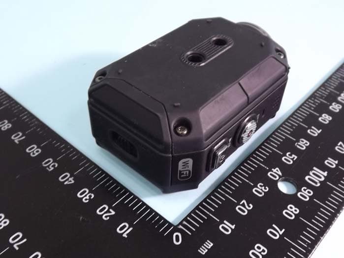
ASIP4C101
Jul 11, 2012Action Camera
Equipment Class
DTS - Digital Transmission System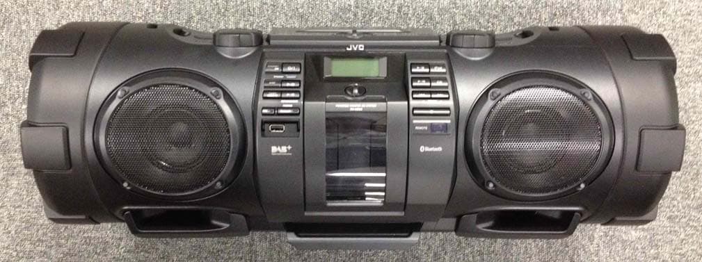
ASIVCB008
Apr 17, 2012POWERED WOOFER CD SYSTEM
Equipment Class
DSS - Part 15 Spread Spectrum Transmitter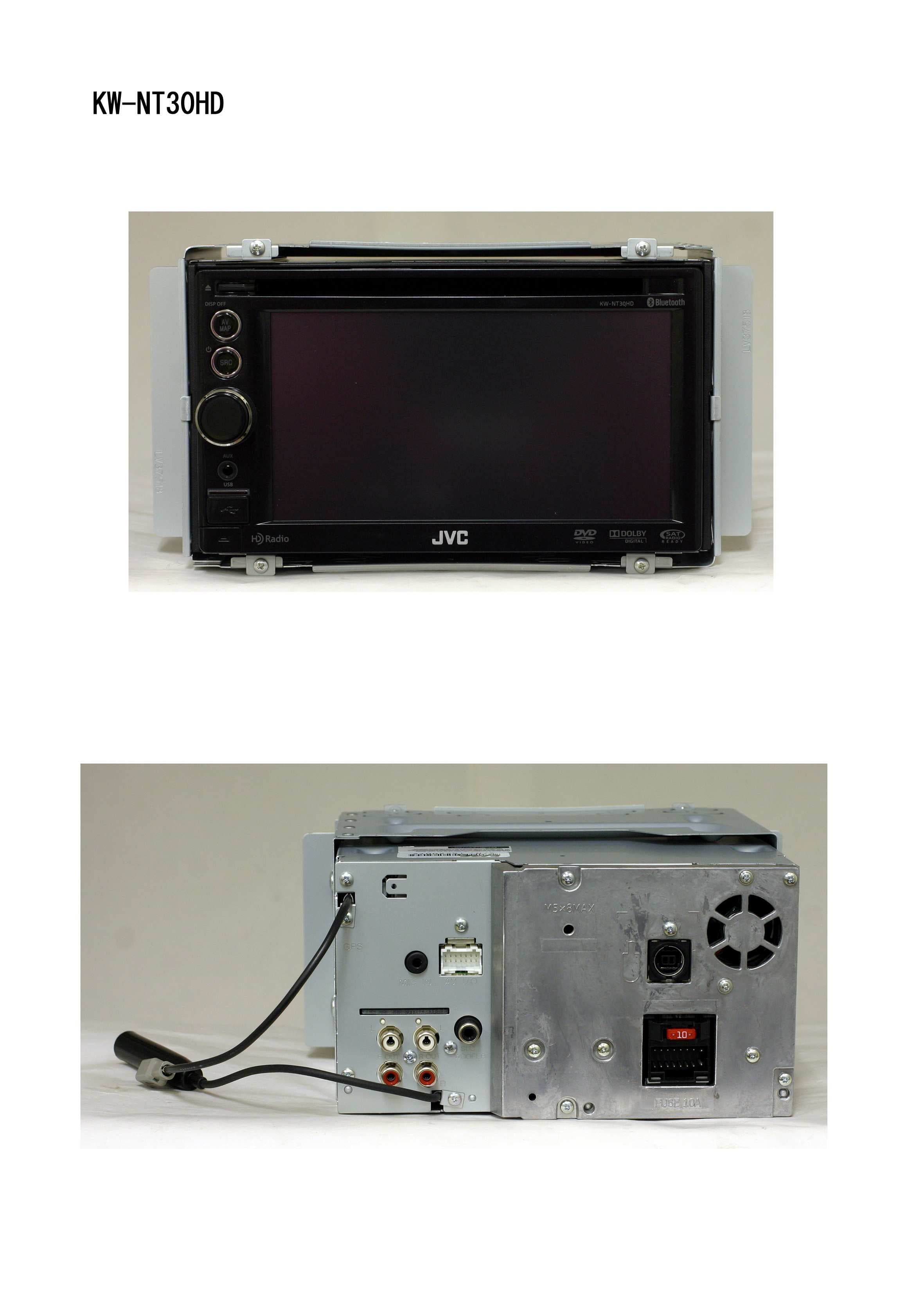
ASIV1B007
Jan 31, 2011GPS Navigation System
Equipment Class
DSS - Part 15 Spread Spectrum Transmitter
ASIVBA006
Nov 29, 2010Bluetooth audio adaptor for vehicle use.
Equipment Class
DSS - Part 15 Spread Spectrum Transmitter