ASLGEMRM-10UX-Band Radar Transceiver
Anschuetz GmbH High Seas Products
Click to zoom
Application Details
- Equipment Class
- MRD - Marine Radar
- Date of Grant
- Jun 30, 2005
- Application Purpose
- Original Equipment
- Date of Application
- Jun 30, 2005
- Equipment Note
- X-Band Radar Transceiver
- Frequency Range
- 9410.00000000 - 9410.00000000
- Country
- Germany
Documents & Files
Document Text
Text extracted from the exhibit documents filed with the FCC. Open a document above to read the original.
Users Manual
3464 100 – 037 NSC 18 Navigational Radar System User Manual 3748DOC020102 Edition 14.JAN.2005 3748DOC020102 Weitergabe sowie Vervielfältigung dieser Unterlage, Verwertung und Mitteilung ihres Inhaltes nicht gestattet, soweit nicht ausdrücklich zugestanden. Zuwiderhandlungen verpflichten zu Schadenersatz. Copying of this document, and giving it to others and the use or communication of the contents thereof, are forbidden without express authority. Offenders are liable to the payment of damages. Toute communication ou reproduction de ce document, toute exploitation ou communication de son contenu sont interdites, sauf autorisation expresse. Tout manquement à cette règle est illicite et expose son auteur au versement de dommages et intérêts. Sin nuestra expresa autorización, queda terminantemente prohibida la reproducción total o parcial de este documento, así como su uso indebido y/o su exhibición o comunicación a terceros. De los infractores se exigirá el correspondiente resarcimiento de daños y perjuicios. Operator Manual Raytheon Marine GmbH Germany R NSC 18 RADAR Table of Contents I 3748DOC020102Edition: 14.JAN.2005 1Introduction1−4. . . . . . . . . . . . . . . . . . . . . . . . . . . . . . . . . . . . . . . . . . . . . . . . . . . . . . . . . . . . . . 1.1Radar System1−5. . . . . . . . . . . . . . . . . . . . . . . . . . . . . . . . . . . . . . . . . . . . . . . . . . . . . . . . . . . . 2OPERATING INSTRUCTIONS2−1. . . . . . . . . . . . . . . . . . . . . . . . . . . . . . . . . . . . . . . . . . . . . . 2.1DISPLAY ORGANIZATION AND SUBMENU STRUCTURE2−2. . . . . . . . . . . . . . . . . . . . 2.2FIRST STEPS IN OPERATION2−7. . . . . . . . . . . . . . . . . . . . . . . . . . . . . . . . . . . . . . . . . . . . 2.2.1Switching ON2−8. . . . . . . . . . . . . . . . . . . . . . . . . . . . . . . . . . . . . . . . . . . . . . . . . . . . . . . . . . . 2.2.2How to use the CURSOR2−10. . . . . . . . . . . . . . . . . . . . . . . . . . . . . . . . . . . . . . . . . . . . . . . . . 2.2.2.1 Cursor in park position2−11. . . . . . . . . . . . . . . . . . . . . . . . . . . . . . . . . . . . . . . . . . . . . . . . . . 2.2.2.2 Cursor symbols2−12. . . . . . . . . . . . . . . . . . . . . . . . . . . . . . . . . . . . . . . . . . . . . . . . . . . . . . . . 2.2.3Radar operator panel2−13. . . . . . . . . . . . . . . . . . . . . . . . . . . . . . . . . . . . . . . . . . . . . . . . . . . . 2.2.4Softkeys and operator controls in NSC display2−15. . . . . . . . . . . . . . . . . . . . . . . . . . . . . . 2.2.4.1 Softkeys in menu bar2−15. . . . . . . . . . . . . . . . . . . . . . . . . . . . . . . . . . . . . . . . . . . . . . . . . . . 2.2.4.2 Operator controls in NSC display2−17. . . . . . . . . . . . . . . . . . . . . . . . . . . . . . . . . . . . . . . . . 2.2.4.3 Toggle fields2−18. . . . . . . . . . . . . . . . . . . . . . . . . . . . . . . . . . . . . . . . . . . . . . . . . . . . . . . . . . . 2.2.4.4 Sliders2−18. . . . . . . . . . . . . . . . . . . . . . . . . . . . . . . . . . . . . . . . . . . . . . . . . . . . . . . . . . . . . . . . 2.2.4.5 Drag and drop2−20. . . . . . . . . . . . . . . . . . . . . . . . . . . . . . . . . . . . . . . . . . . . . . . . . . . . . . . . . 2.2.5System reset2−21. . . . . . . . . . . . . . . . . . . . . . . . . . . . . . . . . . . . . . . . . . . . . . . . . . . . . . . . . . . . 2.2.6Switching OFF the NSC radar system2−22. . . . . . . . . . . . . . . . . . . . . . . . . . . . . . . . . . . . . . 2.3DISPLAY OPERATIONS AND INDICATORS2−24. . . . . . . . . . . . . . . . . . . . . . . . . . . . . . . . . 2.3.1Sensitivity controls2−25. . . . . . . . . . . . . . . . . . . . . . . . . . . . . . . . . . . . . . . . . . . . . . . . . . . . . . . 2.3.1.1 Gain and clutter processing2−25. . . . . . . . . . . . . . . . . . . . . . . . . . . . . . . . . . . . . . . . . . . . . . 2.3.1.2 TUNE2−25. . . . . . . . . . . . . . . . . . . . . . . . . . . . . . . . . . . . . . . . . . . . . . . . . . . . . . . . . . . . . . . . . 2.3.1.3 GAIN2−27. . . . . . . . . . . . . . . . . . . . . . . . . . . . . . . . . . . . . . . . . . . . . . . . . . . . . . . . . . . . . . . . . 2.3.1.4 SEA2−27. . . . . . . . . . . . . . . . . . . . . . . . . . . . . . . . . . . . . . . . . . . . . . . . . . . . . . . . . . . . . . . . . . 2.3.1.5 RAIN RATE2−29. . . . . . . . . . . . . . . . . . . . . . . . . . . . . . . . . . . . . . . . . . . . . . . . . . . . . . . . . . . . 2.3.1.6 Filtering rain clouds FTC2−30. . . . . . . . . . . . . . . . . . . . . . . . . . . . . . . . . . . . . . . . . . . . . . . . 2.3.1.7 CFAR 2−30. . . . . . . . . . . . . . . . . . . . . . . . . . . . . . . . . . . . . . . . . . . . . . . . . . . . . . . . . . . . . . . . 2.3.1.8 Search and rescue transponder SART ON/OFF (option)2−31. . . . . . . . . . . . . . . . . . . . . 2.3.1.9 Pulse width selection2−33. . . . . . . . . . . . . . . . . . . . . . . . . . . . . . . . . . . . . . . . . . . . . . . . . . . 2.3.1.10 Interference selection2−34. . . . . . . . . . . . . . . . . . . . . . . . . . . . . . . . . . . . . . . . . . . . . . . . . . . 2.3.1.11 Echo expansion2−34. . . . . . . . . . . . . . . . . . . . . . . . . . . . . . . . . . . . . . . . . . . . . . . . . . . . . . . . 2.3.2Radar video displays2−35. . . . . . . . . . . . . . . . . . . . . . . . . . . . . . . . . . . . . . . . . . . . . . . . . . . . . 2.3.2.1 Ship heading marker2−35. . . . . . . . . . . . . . . . . . . . . . . . . . . . . . . . . . . . . . . . . . . . . . . . . . . . 2.3.2.2 Relative Motion (R), Relative Motion (T), True Motion2−35. . . . . . . . . . . . . . . . . . . . . . . 2.3.2.3 North Up, Head Up, Course Up and Repeater Up2−39. . . . . . . . . . . . . . . . . . . . . . . . . . Operator Manual Table of Contents II 3748DOC020102Edition: 14.JAN.2005 2.3.3Radar video settings2−43. . . . . . . . . . . . . . . . . . . . . . . . . . . . . . . . . . . . . . . . . . . . . . . . . . . . . 2.3.3.1 Range RNG2−43. . . . . . . . . . . . . . . . . . . . . . . . . . . . . . . …
Text truncated - open the document above for the full version.
Users Manual
+ − Operator Manual Raytheon Marine GmbH Germany R NSC 18 RADAR 2−67 3748DOC020102Edition: 14.JAN.2005 2.4ARPA FUNCTION This chapter describes the operation of the automatic radar plotting aid (ARPA). NOTE The NSC ARPA information is considered to assist decision making in the current situation. The resulting assessment with regard to avoiding collisions must be made independently in accordance with the valid regulations! 2.4.1General Information •Requirements for optimum ARPA support The following requirements must be met on the NSC Radar to achieve optimum ARPA functionality. −The sensitivity controls are optimally adjusted for the current weather conditions −Before you start to use this function you need to select a RANGE higher than 6 NM for the ZONE settings. The zone might not be visible at lower ranges. −Heading e.g. gyro and Speed (log, course over water (W) or course over ground (B)) •Target acquisition can be used to manually or automatically acquire up to 70 targets. The tracking data for selected targets is displayed in the ARPA information window. Operator Manual 2−68 3748DOC020102Edition: 14.JAN.2005 •ARPA alarms ARPA displays alarm messages (see also chapter 2.3.6.4) and artificial symbols (see ARPA SYMBOLS) visually and acoustically. −“Dangerous Targets Alarm” This alarm is triggered as soon as a tracked target exceeds the set limits for CPA or TCPA (see chapter 2.4.2). −“Guard Zone Alarm” This alarm is triggered as soon as an untracked target enters an acquisition / guard zone. −“Target Lost” This alarm indicates that the tracked target has been lost. −“Target Overflow” This alarm is triggered if more than 70 targets have been acquired. This situation can be resolved by deleting acquired targets that are of no interest. •ARPA symbols When using the ARPA function, the radar video displays various artificial symbols that describe the following situations. Operator Manual Raytheon Marine GmbH Germany R NSC 18 RADAR 2−69 3748DOC020102Edition: 14.JAN.2005 SHOW Indicates that target data is displayed in the ARPA INFO window. TEMP After acquisition, the target is observed for a set period of time. SHOW This state is indicated if the current CPA/TCPA collision conditions are met. The target vector flashes. CONTACT This state describes a target which has entered the warning/acquisition zone. The symbol flashes. LOST This state is indicated if a target has been lost for a short time. The target has passed the warning and acquisition zones. Figure: 2−34 ARPA display symbols This state is indicated if the trial maneuver is activated. The symbol flashes. TEST This state is indicated if the test function has been called up. The symbol flashes. GROUND Ground referencing. TRIAL TRAIL SITUATION This state is indicated if the current CPA/TCPA collision conditions are met in the trial maneuver. The symbol flashes. •ARPA colors The NSC Radar ARPA function includes the following color assignments. −Ship heading marker, SHM−WHITE Vector (TRUE)−PURPLE −Tracked target− RED − Vector − RED − Past Pos − RED − Trails −GRAY− −CPA/TCPA zone − RED − −Acquisition zone− YELLOW − −Guard zone− RED − −Exclusion zone− GREEN − −Artificial ARPA symbols− RED − (PCP/CPA) Left Operator Manual 2−70 3748DOC020102Edition: 14.JAN.2005 2.4.2MANUAL PLOTTING − ACQ TGT − Targets can be manually acquired using the trackball and the cursor. The target information (ARPA INFO softkey) can include slight tolerances caused by possible influencing parameters such as weather conditions, heading sensor tolerance or log sensor tolerance. DClick the softkey Position the cursor on the object identified as the target; press the Left button. The target is acquired by the computer and given its synthetic symbol, corresponding to the tracking status (TRACKED, MISSED, LOST,..). Operator Manual Raytheon Marine GmbH Germany R NSC 18 RADAR 2−71 3748DOC020102Edition: 14.JAN.2005 2.4.3AUTOMATIC PLOTTING − ARPA MENU − Automatic plotting means that the radar can acquire and track targets automatically. The operator can define acquisition zones. As soon as a target enters such a zone, it is plotted and tracked by the radar. ARPA acquisition zones •CPA/TCPA limits •Acquisition zone •Guard zone •Exclusion zone NOTE Despite all the advantages of automatic target acquisition, it may be the case that: Certain targets cannot be acquired due to the current weather conditions. Targets cannot be acquired due to the set acquisition zone. Targets cannot be acquired due to their size and material. The target information (ARPA INFO softkey) can include slight tolerances caused by possible influencing parameters such as weather conditions, heading sensor tolerance or log sensor tolerance. Operator Manual 2−72 3748DOC020102Edition: 14.JAN.2005 2.4.4CPA/TCPA ARPA constantly evaluates the closest point of approach (CPA) and the time to closest point of approach (TCPA) status of each tracked target. This CPA/TCPA zone is available with predefined values. The CPA/TCPA values are generally ship−specific and must be adapted to the profile of the ship. The ship’s profile includes features such as stopping distance, sea area and visibility. Acquired targets that move inside the radius (CPA) or the time threshold (TCPA) generate a “CPA/TCPA Alarm” in the message display and the relevant target is simultaneously assigned a flashing symbol. The CPA/TCPA zone can be shown or hidden in the radar video as required. Operator Manual Raytheon Marine GmbH Germany R NSC 18 RADAR 2−73 3748DOC020102Edition: 14.JAN.2005 2.4.4.1Determining the CPA/TCPA radius The CPA/TCPA radius can quickly be adjusted to the desired situation as shown in Figure: 2−35. Procedure: Step 1Open the ARPA menu Step 2 Show or hide the radius in the radar video Step 3 Edit and apply individual values for CPA and TCPA Step 4 Complete the input Step 1 Figure: 2−35 CPA/TCPA ZONE Step 3 Step 2 Left Step 4 ARPA symbols Collision conditions Sequence of actions Result: If a tracked target moves inside the set lim…
Text truncated - open the document above for the full version.
Block Diagram
Prüfaufbau NSC18 mit TCU und GEM-Pedestal: Prüfaufbau NSC25: Prüfaufbau NSC34: Prüfaufbau ISU (Interswitch unit):
External Photos
ANNEX 2 TO TEST REPORT # EMCC-030430C, 2005-MAY-09 Page 1 of 6 Radio Laboratories EMC LABORATORIES TTI-P-G 094/94 TTI-P-G 074/95 EMCC DR. RAŠEK Moggast 72-74 91320 Ebermannstadt Germany FCC Registration # 90566 Telephone: +49-9194-9016 Telefax: +49-9194-8125 Mail: [email protected] Web: http://www.emcc.de Photographs of EUT Overall view of system: TX scanner unit (EUT), display unit, connection module, dummy load, cabling EUT, side view ANNEX 2 TO TEST REPORT # EMCC-030430C, 2005-MAY-09 Page 2 of 6 Radio Laboratories EMC LABORATORIES TTI-P-G 094/94 TTI-P-G 074/95 EMCC DR. RAŠEK Moggast 72-74 91320 Ebermannstadt Germany FCC Registration # 90566 Telephone: +49-9194-9016 Telefax: +49-9194-8125 Mail: [email protected] Web: http://www.emcc.de EUT, front view Labeling
ID Label/Location Info
FCC ID: ASLGEMRM-10U X Band Pedestal XCVR Raytheon Marine GmbH D-24106 Kiel, Germany
Internal Photos
ANNEX 2 TO TEST REPORT # EMCC-030430C, 2005-MAY-09 Page 3 of 6 Radio Laboratories EMC LABORATORIES TTI-P-G 094/94 TTI-P-G 074/95 EMCC DR. RAŠEK Moggast 72-74 91320 Ebermannstadt Germany FCC Registration # 90566 Telephone: +49-9194-9016 Telefax: +49-9194-8125 Mail: [email protected] Web: http://www.emcc.de EUT, opened EUT, internal view ANNEX 2 TO TEST REPORT # EMCC-030430C, 2005-MAY-09 Page 4 of 6 Radio Laboratories EMC LABORATORIES TTI-P-G 094/94 TTI-P-G 074/95 EMCC DR. RAŠEK Moggast 72-74 91320 Ebermannstadt Germany FCC Registration # 90566 Telephone: +49-9194-9016 Telefax: +49-9194-8125 Mail: [email protected] Web: http://www.emcc.de EUT, internal view, cover EUT, internal view, magnetron, labeling ANNEX 2 TO TEST REPORT # EMCC-030430C, 2005-MAY-09 Page 5 of 6 Radio Laboratories EMC LABORATORIES TTI-P-G 094/94 TTI-P-G 074/95 EMCC DR. RAŠEK Moggast 72-74 91320 Ebermannstadt Germany FCC Registration # 90566 Telephone: +49-9194-9016 Telefax: +49-9194-8125 Mail: [email protected] Web: http://www.emcc.de EUT, internal view, labeling of transceiver plate Peripheral, display and control unit ANNEX 2 TO TEST REPORT # EMCC-030430C, 2005-MAY-09 Page 6 of 6 Radio Laboratories EMC LABORATORIES TTI-P-G 094/94 TTI-P-G 074/95 EMCC DR. RAŠEK Moggast 72-74 91320 Ebermannstadt Germany FCC Registration # 90566 Telephone: +49-9194-9016 Telefax: +49-9194-8125 Mail: [email protected] Web: http://www.emcc.de Peripheral, display and control unit Peripheral, display and control unit, labeling
Operational Description
REF. AF503510DATE 11/07/02REV. 1PAGE 1 of 12 TECHNICAL SPECIFICATION SCANNER UNIT 10KW SU 70-10NR The copyright of this technical specification is the property of GEM Elettronica S.R.L.. The handbook is issued on the condition that is not to be copied, reprinted or reproduced, nor its contents disclosed either wholly or in part to any third part without the consent in writing of or in accordance with the conditions of a contract with GEM Elettronica S.R.L.. The specification may be subject to variation as a result of subsequent improvements in design or technique. Drafted by:Data Controlled by:Data Approved by:Data REF. AF503510DATE 11/07/02REV. 1PAGE 2 of 12 REVISIONS INDEX REV.DESCRIPTIONAPPROVATIONDATE 0ORIGINAL24/01/2002 111/07/2002 REF. AF503510DATE 11/07/02REV. 1PAGE 3 of 12 GENERAL INDEX 1.General.............................................................................................................................4 2.Technical specification...................................................................................................4 3.Array units........................................................................................................................5 4.Other features..................................................................................................................5 4.1Environmental features................................................................................................5 4.2Reliability.......................................................................................................................5 4.3Dimensions and weights.............................................................................................5 5.Signals description.........................................................................................................7 6.Connectors.......................................................................................................................9 FIGURES INDEX Fig. 1 – Dimensions and weight of the scanner unit SU70-10NR....................................10 Fig. 2 – Dimensions and weights of the available array units...........................................11 Fig. 3 – CB20 cable heading scanner unit..........................................................................12 TABLES INDEX Table 1 – Technical features of the available antenna arrays..............................................5 Table 2 – Interface signals.......................................................................................................8 Table 3 – Operation mode and Pulse Width..........................................................................8 Table 4 – Suitable frequencies for the TRG trigger signal....................................................8 Table 5 – Interconnection between the terminal board J8 of the scanner unit and display unit..............................................................................................................9 Table 6 – Interconnection between the terminal board J9 of the scanner unit and display unit..............................................................................................................9 REF. AF503510DATE 11/07/02REV. 1PAGE 4 of 12 1. GENERAL The scanner unit SU70-10NRR has been designed for surface search systems. This unit can be connected to systems of radar presentation and management. The scanner unit SU70-10NR also features an extreme reliability and duration of operation under adverse climatic conditions. The whole electronics and the motor group are contained in a waterproof pedestal in aluminum alloy, easily accessible for possible maintenance activities. 2. TECHNICAL SPECIFICATION The technical features of the scanner unit are: Peak power (nominal):10 kW (typical) Radiation frequency:9410 ± 30 MHz. Pulse Width:80 ns – 300 ns – 600 ns – 1.2 μs (with ± 10% tolerance) Pulse Repetition Frequency:3200 Hz – 1600 Hz – 800 Hz – 500 Hz (with ± 10% tolerance) Modulator:fully solid state Receiver type:logarithmic, fully solid state Dynamic range:= 100 dB Intermediate Frequency (I.F.):60 MHz ± 2 MHz I.F. bandwidth:20 MHz with short and medium pulses; 4 MHz with long and extralong pulses (with ± 10% tolerance) Front End:microwave integrated circuit Noise figure: = 4 dB Duplexer:ferrite circulator with solid state limiter diode Antenna rotation speed:22 ± 2 r.p.m. Tolerable relative wind speed:100 Kts REF. AF503510DATE 11/07/02REV. 1PAGE 5 of 12 3. ARRAY UNITS In Table 1 are given the technical specifications of the antenna arrays available with the Scanner Unit SU70-10NR; dimensions and weights are shown in Fig. 2. ARRAY MODELAU11-04NRAU11-06NRAU11-07NRAU11-09NR Length4 feet6 feet7.5 feet9 feet TypeSlotted waveguide Frequency bandX band, λ = 3.2 cm, frequency range 9410 ± 60 MHz PolarizationHHHH/C Horizontal beamwidth to –3dB≤ 1.9°≤ 1.2°≤ 1.1°≤ 0.85° Vertical beamwidth to –3dB~ 25°~ 25°~ 25°~ 25° Sidelobes within 10°-26dB-26dB-26dB-26dB Sidelobes outside 10°-30dB-30dB-30dB-30dB Gain≥ 27dBi≥ 29dBi≥ 30dBi≥ 31dBi Rotation speed22 rpm (selectable speed available as an option) Tolerable relative wind speed100 knots Table 1 – Technical features of the available antenna arrays 4. OTHER FEATURES 4.1 Environmental features Operative temperature:from -25°C to +55°C Storage temperature:from -40°C to +70°C Relative humidity:up to 90% at +40°C 4.2 Reliability The MTBF value for the scanner unit SU70-10NR has been estimated to be about 30000 hours. 4.3 Dimensions and weights The dimensions and the weight of the scanner unit SU70-10NR are shown in Fig. 1. REF. AF503510DATE 11/07/02REV. 1PAGE 6 of 12 The dimensions and weights of the antenna arrays suitable for mounting on the SU70-10NR scanner unit are shown in Fig. 2. REF. AF503510DATE 11/07/02REV. 1PAGE 7 of 12 5. SIGNALS DESCRIPTION A list of all the scanner unit interface signals follows in Table 1. The operation of the control signals SB_OP, RAD0 and RAD1 is shown in Table 2. In Table 3 are given t…
Text truncated - open the document above for the full version.
Parts List/Tune Up Info
3748DOC020302 Edition 14.JAN.2005 Service Manual Navigational Radar System NSC 18 RMarine RMarine Weitergabe sowie Vervielfältigung dieser Unterlage, Verwertung und Mitteilung ihres Inhaltes nicht gestattet, soweit nicht ausdrücklich zugestanden. Zuwiderhandlungen verpflichten zu Schadenersatz. Copying of this document, and giving it to others and the use or communication of the contents thereof, are forbidden without expressauthority. Offenders are liable to the payment of damages. Toute communication ou reproduction de ce document, toute exploitation ou communication de son contenu sont interdites, sauf autorisation expresse. Tout manquement à cette règle est illicite et expose son auteur au versement de dommages et intérêts. Sin nuestra expresa autorización, queda terminantemente prohibida la reproducción total o parcial de este documento, así como su uso indebido y/o su exhibición o comunicación a terceros. De los infractores se exigirá el correspondiente resarcimiento de daños y perjuicios. 3748DOC020302 Edition 14.JAN.2005 Raytheon Marine GmbH Germany R NSC 18 RADAR Safety Regulation Service and Installation Manual I 3748DOC020302Edition: 14.JAN.2005 SAFETY REGULATION "Warning! Caution during maintenance and repairs: Avoid contact with live electrical circuits! All relevant safety regulations such as, e.g. VDE, VGB4, OSHA 1919 and other relevant safety standards must be ob served. "Caution! Maintenance and repairs must only be carried out by trained and qualified personal with knowledge of the national safety regulations for electrical devices. Observe handling regulations! Electrostatic sensitive components. Removal or insertion of a subgroup or printed wiring board with live voltage can lead to severe damage. Never insert fuses with other values than those stipulated! "Caution! If acting without authority any modifications the NSC 18 can be affects the functionality and lose the GUARANTY. Service and Installation Manual Safety Regulation II 3748DOC020302Edition: 14.JAN.2005 Radiation Hazard CAUTION UNDER NORMAL OPERATING CONDITIONS, THE ELEC- TROMAGNETIC ENERGY EMITTED BY THIS RADAR OP- ERATION IS SAFELY BELOW GOVERNMENT EXPO- SURE MAXIMUM STANDARDS. 1. THE TRANSMITTER SHOULD ONLY BE OPERATED WHEN THE ANTENNA IS ROTATING. 2. THE RADAR SYSTEM SHOULD BE TURNED OFF BEFORE APPROACHING WITHIN 6 FEET OF THE ANTENNA FOR X−BAND. 3. THE ANTENNA SHOULD NOT BE RELOCATED OR REPOSITIONED WITHOUT CONSULTING THE RAYTHEON MARINE COMPANY SERVICE ORGANIZATION OR AN AUTHORIZIED DEALER. Raytheon Marine GmbH Germany R NSC 18 RADAR Safety Regulation Service and Installation Manual III 3748DOC020302Edition: 14.JAN.2005 There is absolutely no danger in handling the external controls of the radar while the radar is in operation. In the radar‘s interior, however are high voltages which are fatally dangerous to anyone careless handling interior components. Be absolutley sure that the radar power switch is OFF before performing repair work or maintenance . Furthermore, even when the power switch is turned off, a high voltage remains in certain parts of the radar circuits. In particular, be careful of the magnetron heater circuit, cathode−ray tube anode circuit, etc.. Utilizing a length of wire with one end fully grounded or an insulated srewdriver, ground all high voltage sections to discharge the residual charges and ensure that no charges remain before touching any part of the high voltage sections. In any case, the most dangerous thing to do is to touch any part of the high voltage sections without making sure that the radar power switch is off. HIGH VOLTAGE Exercise care when approaching a rotating antenna. Be sure to turn off the radar power switch before performing maintenance or inspection of the antenna. Also, make sure that nothing or no one is near the antenna when turning on the radar power supply. ATTENTION Service and Installation Manual Safety Regulation IV 3748DOC020302Edition: 14.JAN.2005 A short exposure to the microwaves radiated by the radar antenna is harmless. However, avoid prolonged exposure to the microwaves. Never look directly into the wave guide while checking transceiver operation, since microwaves are especially harmful to the eyes. The radiation of microwaves can be checked with a neon tube . The neon tube will glow in the presence of microwaves. MICROWAVE RADIATION Service and Installation Table of Contents VI 3748DOC020502Edition: 14.JAN.2005 1Installation1 − 1. . . . . . . . . . . . . . . . . . . . . . . . . . . . . . . . . . . . . . . . . . . . . . . . . . . . . . . . . . . . . . . 1.1SAFETY INFORMATION1 − 1. . . . . . . . . . . . . . . . . . . . . . . . . . . . . . . . . . . . . . . . . . . . . . . . . . 1.1.1Technical Specification1 − 2. . . . . . . . . . . . . . . . . . . . . . . . . . . . . . . . . . . . . . . . . . . . . . . . . . . 1.1.2Checks made prior to putting into operation1 − 3. . . . . . . . . . . . . . . . . . . . . . . . . . . . . . . . . 1.2Scope of supply1 − 4. . . . . . . . . . . . . . . . . . . . . . . . . . . . . . . . . . . . . . . . . . . . . . . . . . . . . . . . . . 1.3Planning the installation and instructions for installation1 − 5. . . . . . . . . . . . . . . . . . . . . . . 1.3.1NSC 18 Radar Display (see dimensional drawing 900−014HP006)1 − 5. . . . . . . . . . . . 1.3.2X−band Pedestal with 6 ft. Antenna1 − 5. . . . . . . . . . . . . . . . . . . . . . . . . . . . . . . . . . . . . . . . 1.4Installation and putting into operation1 − 7. . . . . . . . . . . . . . . . . . . . . . . . . . . . . . . . . . . . . . . 1.4.1NSC 18 Radar Display (mechanical installation)1 − 7. . . . . . . . . . . . . . . . . . . . . . . . . . . . . 1.4.2X−Band Pedestal with 6ft. Antenna (mechanical installation)1 − 12. . . . . . . . . . . . . . . . . . 1.4.2.1 Pedestal1 − 12. . . . . . . . . . . . . . . . . . . . . . . . . . . . . . . . . . . . . . . . . . . . . . . . . . . . . . . . . . . . . . 1.4.2.2 Antenna1 − 13. . . . . . . . . . . . . . . . . . . . . . . . . . . . . …
Text truncated - open the document above for the full version.
Parts List/Tune Up Info
Service and Installation Manual Raytheon Marine GmbH Germany R NSC RADAR 2 − 1 3748DOC020302Edition: 14.JAN.2005 2SETUP, TEST and CALIBRATION It is recommended to follow the procurement sequences. It is recommended to note adjusted values. For doing this SETUP procedure you have to use − a USB keyboard −a USB memory stick −PS 2 mouse USBPS 2 mouse Figure: 2−1 NSC 18 back view Service and Installation Manual 2 − 2 3748DOC020302Edition: 14.JAN.2005 2.1System Setup and Test 1. TRANSCEIVERSetting to define the transceivers and displays of the equipment. see chapter 2.4 2. VIDEO SET/ TEST Signal trigger true bearing and true distance (see also Video Levels a.m.) see chapter 2.4.4 3. USER PREF.Setting of:Pulse with Heading line Curved Heading line Arpa Configuration CRP Adjustment of Transceivers: − Antenna high − Pedestal fwd/aft pos. − Pedestal port/stbd pos. − Transmission line length − Zero range − Antenna Azimuth Offset − Tuning preset − Noise Preset − Video Level − Sector Blanking see chapter 2.6.1 see chapter 2.4 see chapter 2.4.3 and 2.4.5 see chapter 2.4.5.1 see chapter 2.4.5.2 see chapter 2.4.5.3 see chapter 2.4.5.4 see chapter 21.4.1 see chapter 2.4.8 4. COM−PORTSSetting of data for all COM portssee chapter 2.7.1 5. DEFAULT/ TEST/SAVE Includes:Installation test Factory test Extended tools (BITE) actually not im- plemented see chapter 2.9.1 6. ETHERNETSetting of dataformat for the ETHERNET interface see chapter 2.8.1 Service and Installation Manual Raytheon Marine GmbH Germany R NSC RADAR 2 − 3 3748DOC020302Edition: 14.JAN.2005 2.2Start of System Setup and Test The service installation and setup menu is found in the STANDBY (step 1) con- dition – SERV. For Testing the menus can be used in any order . For Installation, at new building or adding new transceivers, follow the chapter 2.4. A keyboard is connected at the USB connector to enable entering LABEL data. Also a USB hub with keyboard and trackball is recommended for NSC18 to make mouse action faster. For software E0010 and later, a USB keyboard is not necessary, an on screen keyboard (OSK) will appear. PASSWORD is “test” step 2 step 1 Figure: 2−2Start of Installation Setup Setup menu can be selected by activating “SERV” (step 2), see Figure: 2−2 Service and Installation Manual 2 − 4 3748DOC020302Edition: 14.JAN.2005 After Selecting “SERV” below mentioned Software−module has to be activated by a doubleclick (see Figure: 2−3 step 1). step 1 Figure: 2−3Software module for Setup procedure After selection of the Software−module the respective program has to be se- lected and started (see Figure: 2−4 step 2). step 2 Figure: 2−4Start program for Setup procedure Service and Installation Manual Raytheon Marine GmbH Germany R NSC RADAR 2 − 5 3748DOC020302Edition: 14.JAN.2005 •Date and Time This is normally always U.T.C.. User can also change it at the Radar Start Menu. •Configuration This is for Radar SETUP, Oscilloscope function and some Built in Testing. •Error Log This is to save an ERROR RECORD to USB memory to send to Raytheon or your Agent or to the Radar Store to receive later. •COM Port (Factory use) Port Viewer tests all data coming into the computer before Raytheon software tries to use it. In workshop testing, connect loopback cables from out puts to inputs to use RUN. •NMEA Data This can be used to check real data inputs as seen by Raytheon Systems from Sensors. •AIS Server AIS data can be over a Network cable from ECDIS, or by direct input to an COM Port. Normally use the RADAR CONFIGURATION menu. This menu does the …
Text truncated - open the document above for the full version.
Contact Information
Applicant
Robert Zissen(Qualification/Certification)
Test Firm
EMCCons Dr. Rasek GmbH & Co.KGChristian Kreller
Technical Specifications
| # | Rule Parts | Frequency Range | Power Output | Emission | Tolerance |
|---|---|---|---|---|---|
| 1 | 80 | 9.41 GHz - 9.41 GHz | 10000 W | 87M4P0N | 0.3190000000 % |
Other Applications from Anschuetz GmbH High Seas Products
ASL-SST3050X
Sep 01, 2026Navigational Radar Pedestal/Transceiver
Equipment Class
TNB - Licensed Non-Broadcast Station TransmitterASL-SST3051S
Sep 01, 2026Navigational Radar Pedestal/Transceiver
Equipment Class
TNB - Licensed Non-Broadcast Station Transmitter
ASLNSX-30U
Sep 08, 2015Shipborne Radar - S-Band Up Mast Transceiver
Equipment Class
TNB - Licensed Non-Broadcast Station Transmitter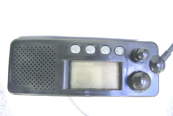
ASLRAY53
Mar 08, 2000VHF-FM Marine Band Transceiver with DSC
Equipment Class
TNB - Licensed Non-Broadcast Station Transmitter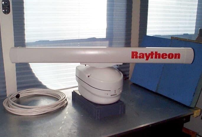
ASLMTX9
Feb 23, 2000Leisure Marine Radar
Equipment Class
MRD - Marine Radar