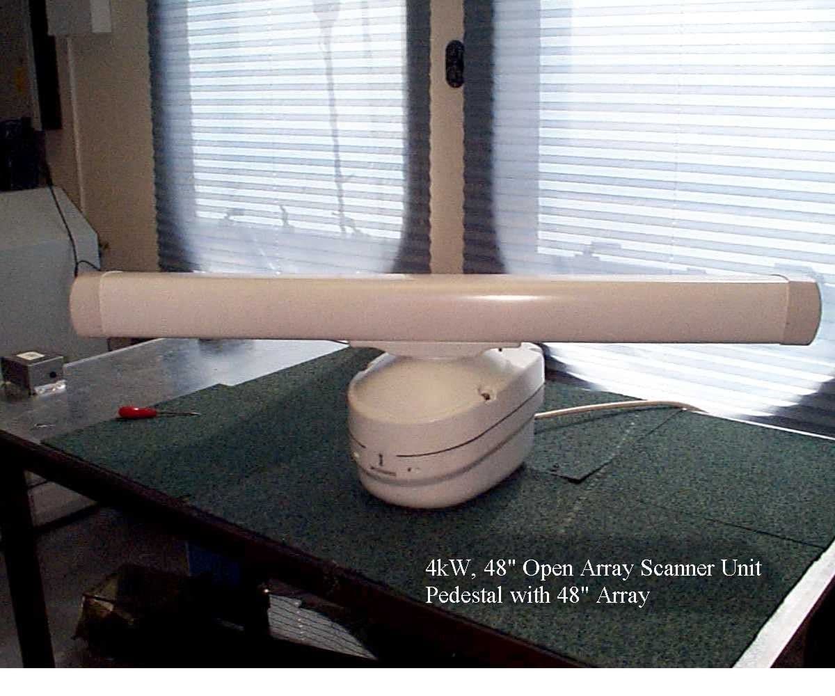
Click to zoom
Application Details
- Equipment Class
- MRD - Marine Radar
- Date of Grant
- Aug 05, 1999
- Application Purpose
- Original Equipment
- Date of Application
- Jun 02, 1999
- Frequency Range
- 9410.00000000 - 9410.00000000
- Country
- Germany
Documents & Files
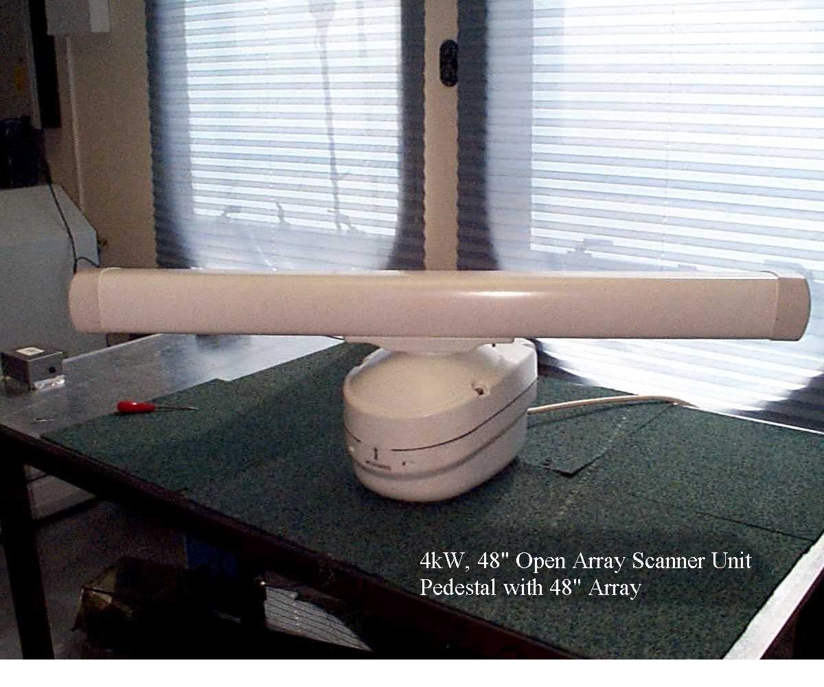
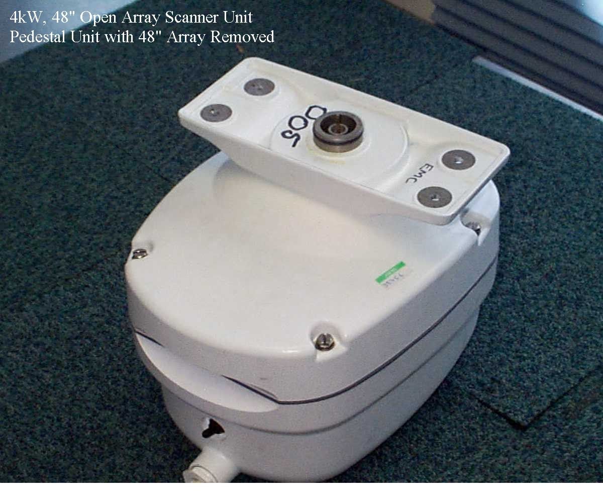
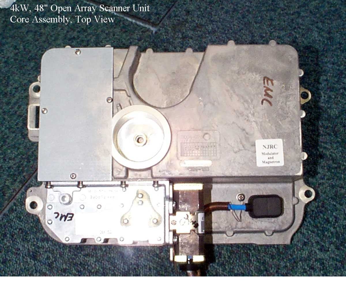
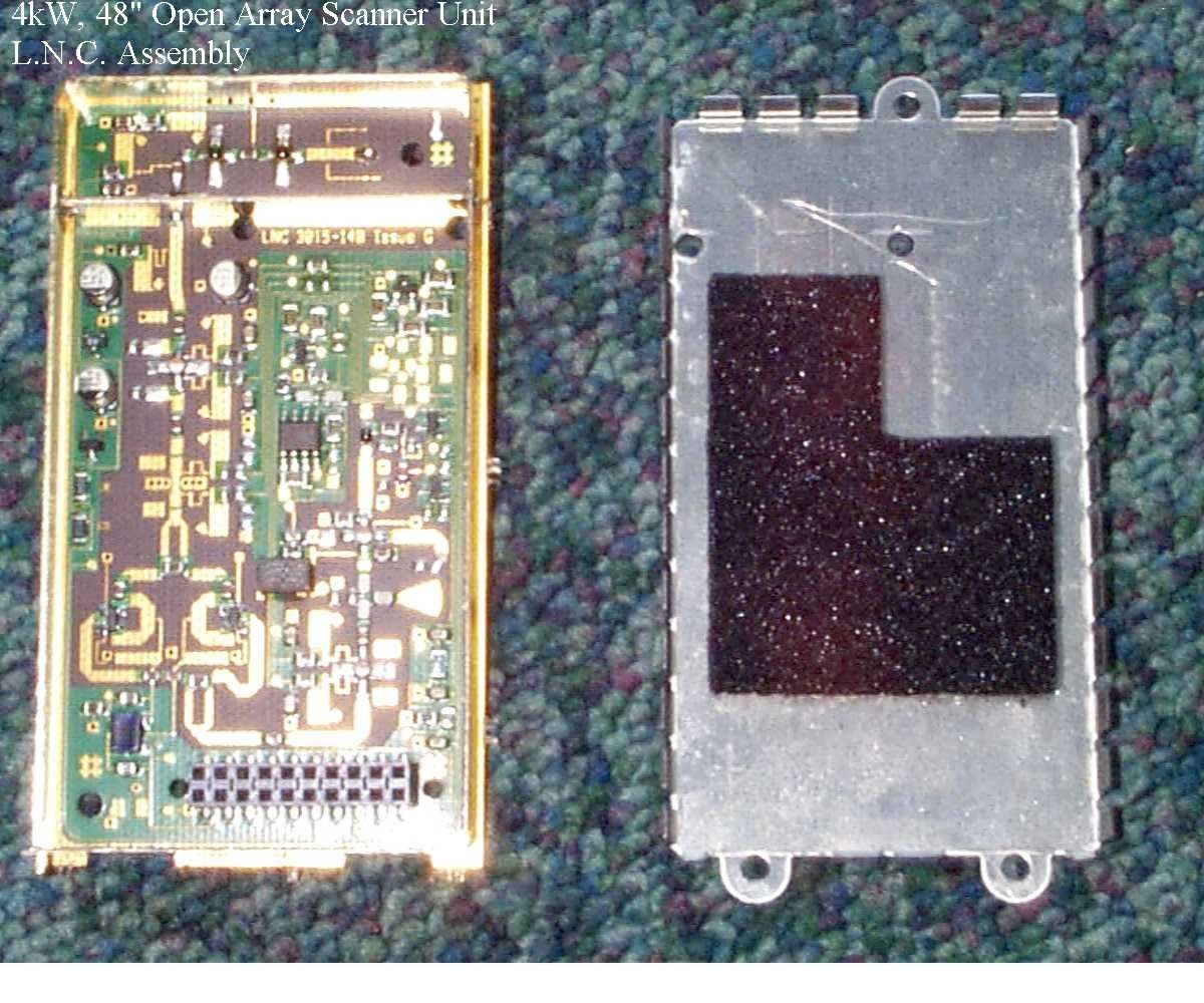
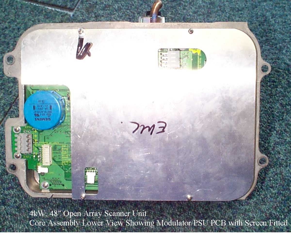
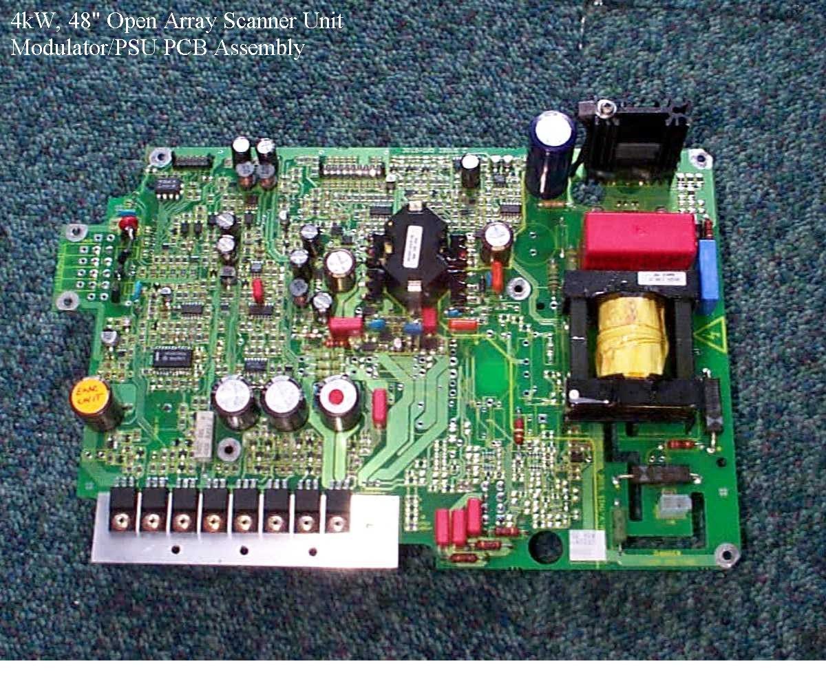
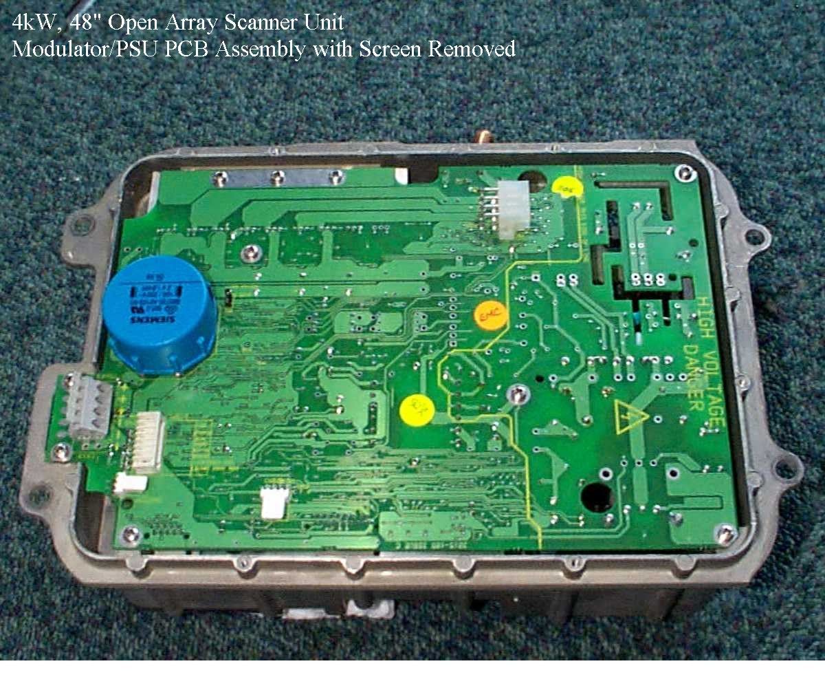
Document Text
Text extracted from the exhibit documents filed with the FCC. Open a document above to read the original.
Users Manual
Pathfinder Radar Scanners Owner’s Handbook Document number: 81154_2 Date: 14th May 1999 154_2cvr.p6513/05/99, 13:171 154_2cvr.p6513/05/99, 13:172 Pathfinder Radar Scanners Owners Handbook May 1999 SAFETY NOTICES This radar equipment must be installed and operated in accordance with the instructions contained in this manual. Failure to do so can result in personal injury and/or navigational inaccuracies. In particular: 1. HIGH VOLTAGE. The scanner unit contains high voltages. Adjustments require specialised service procedures and tools only available to qualified service technicians – there are no user serviceable parts or adjustments. The operator should never remove the scanner unit cover or attempt to service the equipment. 2. ELECTROMAGNETIC ENERGY. The radar scanner transmits electromagnetic energy. It is important that the radar is turned off whenever personnel are required to come close to the scanner to perform work on the scanner assembly or associated equipment. It is recommended that the radar scanner is mounted out of range of personnel (above head height). Do not look directly at the antenna at close range as your eyes are the most sensitive part of the body to electromagnetic energy. When properly installed and operated, the use of this radar will conform to the requirements of ANSI/IEEE C95.1-1992 Standard for Safety Levels with Respect to Human Exposure to Radio Frequency Electromagnetic Fields, 3 Hz to 300 GHz and NRPB, Board Statement on Restrictions on Human Exposure to Static and Time Varying Electromagnetic Fields and Radiation, Doc NRPB, No. 5 (1993). 3. NAVIGATION AID. This radar unit is only an aid to navigation. Its accuracy can be affected by many factors, including equipment failure or defects, environmental conditions, and improper handling or use. It is the user’s responsibility to exercise common prudence and navigational judgements. This radar unit should not be relied upon as a substitute for such prudence and judgement. 154_2saf.p6513/05/99, 13:171 Pathfinder Radar Scanners RAYTHEON MARINE products are supported by a network of Authorized Service Representatives. For information on Raytheon products and services, contact either of the following: UNITED STATESRaytheon Marine Company 676 Island Pond Road Manchester, NH 03109-5420 Telephone: (603) 647-7530 800 539-5539 Fax: (603) 634-4756 EUROPERaytheon Marine Limited Anchorage Park Portsmouth Hampshire PO3 5TD England Telephone: 01705 693611 Fax: 01705 694642 Copyright © Raytheon Marine Company 1999 The technical and graphical information contained in this handbook, to the best of our knowledge, was correct as it went to press. However, the Raytheon policy of continuous improvement and updating may change product specifications without prior notice. As a result, unavoidable differences between the product and handbook may occur from time to time, for which liability cannot be accepted by Raytheon. Raytheon is a registered trademark of Raytheon Company. SeaTalk is a registered trademark of Raytheon Marine Europe Limited. HSB is a trademark of Raytheon Marine Company. Pathfinder is a trademark of Raytheon Marine Company. This product contains technology provided under license by Acorn Group plc. The copyright of this intellectual property is acknowledged by Raytheon Marine Company, as are Acorn’s trademarks and patents. Acorn’s world wide web address is http://www.acorn.com. 154_2saf.p6513/05/99, 13:172 Prefaceiii Preface This handbook describes the following Pathfinder radar scanners from Raytheon: 2D18" 2 kW Radome Scanner 4D24" 4 kW Radome Scanner 5S48" 4 kW Open Array Scanner CAUTION The 5S 48" Open Array Scanner must not be used with the SL70 or Autohelm 7” LCD Display Unit. This may result in damage to the display due to the high power requirements of the open array scanner. The handbook contains very important information on the installation and operation of your new equipment. In order to obtain the best results in operation and performance, please read this handbook thoroughly. Raytheon’s Product Support representatives or your local dealer will be available to answer any questions you may have. Warranty To register your Pathfinder Radar Scanner ownership, please take a few minutes to fill out the warranty registration card found at the end of this handbook. It is very important that you complete the owner information and return the card to the factory in order to receive full warranty benefits. EMC Conformance All Raytheon equipment and accessories are designed to the best industry standards for use in the leisure marine environment. Their design and manufacture conforms to the appropriate Electromagnetic Compatibility (EMC) standards, but correct installation configuration is essential to maintain EMC performance. Note: Then 5S 48” Open Array Scanner has NOT been tested with the SL70 or Autohelm 7” LCD Display Unit for EMC conformance. 154_2pre.p6513/05/99, 13:173 iv Pathfinder Radar Scanners 154_2pre.p6513/05/99, 13:174 Contentsv Contents Chapter 1: Overview............................................................................ 1 1.1 Introduction................................................................................. 1 EMC installation guidelines......................................................... 2 1.2 Unpacking and inspecting the components.................................... 3 Radome scanners................................................................... 3 Open array scanners............................................................... 4 1.3 Selecting the scanner unit site........................................................ 5 Mounting surface: sailboats.................................................... 8 Mounting surface: power boats............................................... 9 Setting the radiation plane....................................................... 9 1.4 Cable runs................................................................................... 10 …
Text truncated - open the document above for the full version.
Block Diagram
Service Manual 83XXX-1-Ch2 3 Part 5 Chapter 2 Chapter 2. Technical Description 4 kW, 48" Open Array Technical Description 2.1 Overview Scanner configuration W/Guide limiter 60dBm (maximum) 4kW Circulator -20dB (nominal) IF Receiver, micro, I/O board Magnetron Low Noise Converter Scanner uplink connection Motor Antenna/Rotary joint assembly Modulator, PSU board Transition D4595-1 Ships power Figure 1. Scanner Block Diagram The system comprises the functional blocks as shown in the above diagram. The basis of operation is as follows: The Modulator, PSU board generates a high voltage pulse of between 60nS and 1uS duration dependant upon the range setting and the corresponding IF/Video filter control lines. This pulse begins on the rising edge of a negative going trigger at a pulse repetition frequency (PRF) also defined by the range setting. The resulting pulse is output to the magnetron which converts the energy into an RF pulse at a frequency of 9.41GHz (nominal). All supply requirements are also provided by the Modulator, PSU board. The RF pulse is routed to an antenna via a 3-port circulator which propagates microwave energy in only one direction and thereby provides isolation between the transmit source and the low noise converter. A rotary joint is used to maintain continuity between a waveguide output from the circulator and a coaxial input to the antenna. The energy is then radiated, with a narrow azimuth beam shape (1.85° for the 48" antenna), with low sidelobe levels (<-22dB). The elevation beamwidth is maintained at approximately 25° in order to illuminate targets during pitch and roll of the transmitting vessel. Echoes are returned due to reflections from potential targets such as boats, buoys, land etc, and in the form of clutter from sea, rain, etc. The returned energy is collected by the same antenna used to transmit the original pulse and is routed through the circulator to the low noise converter (LNC). These comparatively low level signals are amplified by a low noise transistor in order to maintain signal/noise performance and are mixed down to an IF frequency of 60MHz nominal for further amplification and subsequent detection. 4 Service Manual 83XXX-1-Ch2 Part 5 Chapter 2 Pathfinder Radar/Chartplotter Series The IF receiver board provides further low noise amplification and adjustable gain to maximise the dynamic range (“dynamic attenuation control”) in the presence of clutter, target and range variations. The IF board also includes a logarithmic detection stage with approximately 50dB dynamic range, which provides a compressed signal output in terms of dB input power versus output Voltage level. Various filtering stages are also employed in the IF Receiver to provide optimum signal/noise characteristics for the detected pulse and to provide some immunity against the bulk effects of rain. The IF Receiver also provides the interface for the up-link commands to the scanner, including clutter and gain selection, 3-phase motor control and display synchronisation pulse generation. Receiver configuration (LNC/IF) The basic configuration of the microwave and IF receiver circuitry is as follows : Low Noise Converter (LNC)IF Receiver Board Filter select logic Limiter LNA 90 deg 90 HYB Switched Filter Logarithmic Detector Video Filter Curve Splitter Autotune Receiver LNC Supplies Scanner uplink MBS / STC / Rain / Sea / Gain Generation and Summing Network Lineariser Lineariser D4055-1 Figure 2. Receiver Configuration (LNC/IF) Low Noise Converter/Limiter (LNC) The primary function of the LNC is to provide low noise amplification of the low level signal returns and mixing to an IF frequency of 60MHz nominal. The low noise amplification is provided by a single low noise FET, with bias conditions, and associated matching set to minimise noise figure and maximise gain and compression levels. Maximum gain is required so as to minimise the noise figure contribution from subsequent stages. The mixing function is carried out in an image reject mixer configuration which reduces image noise by 20dB nominal in order to minimise the degradation in overall noise figure. Protection is provided in the form of three limiter diodes which are configured to become forward biased in the presence of increasing RF power. NOTE. There are no user / dealer serviceable parts within the LNC due to its high frequency of operation. Service Manual 83XXX-1-Ch2 5 Part 5 Chapter 2 Chapter 2. Technical Description LNA Limiter 90 degrees Mixer Constant current bias circuitry +5Volts -5Volts Ground μW I/P VCO tune compensation 90 HYB 60MHZIF Tune_V D4056-1 Figure 3. LNC Configuration D4598-1 Modulator/PSU/Motor Magnetron 3-Phase Motor P7 LNC P1 P2P4 Ship's Heading Sensor CN2 CN5 CN7 CN8 CN3CN6 CN10 CN9 Ships Supply Display Unit Scanner Disable Switch IF Receiver CN2 IF Inter-connect CN3 3-Phase Motor CN5 Ships Header Transducer CN6 Magnetron CN7 IF Display Interface Inter-connect CN8 Display Inter-connect CN9 Scanner Disable Switch CN10 Ships Power Note: CN3, CN8, CN9, CN10 are fitted to non-component side to give access to the installer. Figure 4. Scanner Interfaces 6 Service Manual 83XXX-1-Ch2 Part 5 Chapter 2 Pathfinder Radar/Chartplotter Series 2.2 Modulator / PSU – Interface Description The interfaces to the Mod/PSU are shown in Figure 4. and the individual signal functions are described below :- Ship Supply Power Input (CN10) Ref.Signal NameTypeStateFunction CN10-7+V_SHIPPower input–Ships power i/p CN10-8 CN1-1–V_SHIPPower input–Ships power return CN1-2 Modulator Control/Status (CN2) Ref.Signal NameTypeStateFunction CN2-18RADAR_TX_ENLogic input1Enable modulator (magnetron) pulses 0Disable modulator, regardless of activity on PRI_PLS CN2-9PW0,Logic inputPW0 PW1Select course modulator pulse width as follows :- CN2-11PW1Logic input00Short pulse 10Medium pulse 01Long pulse 11Very long pulse CN2-16PN_ADJUSTAnalogue input0-5.0VAnalogue voltage adjusts fine transmit pulse width. CN2-13PTX_ADJUSTAnalogue input0-5.0VAnal…
Text truncated - open the document above for the full version.
Cover Letter(s)
Raytheon Marine Limited, Registered in England. Company no. 1177969 Registered office: Anchorage Park, Portsmouth, PO3 5TD Raytheon Marine Company Recreational Products Anchorage Park Portsmouth Hampshire PO3 5TD England (01705) 693611 (01705) 694642 fax Federal Communications Commission Equipment Approval Branch 12th, May 1999 Gentlemen, Certification of Raytheon 'Pathfinder' Radars Models: R75, R75RC, RL75 & RL75RC FCC ID: ASLMTX5 This equipment has been tested in accordance with the technical requirements contained in FCC Rules 47CFR Part 2 and Part 80 and has been found to fully comply with these standards. Testing was carried by Radio Frequency Investigation Limited (RFI) on behalf of Raytheon Marine Limited. RFI is a U.K. Competent Body and has FCC and NAMAS accreditation. The tests were performed using measurement procedures and standards consistent with industry and Commission standards and the results obtained demonstrated equipment compliance to the appropriate standards. Each unit manufactured, imported, or marketed, as defined in the Commission's regulations, will conform to the sample(s) tested within variations that can be expected due to quantity production on a statistical basis. I further certify that the necessary measurements will be made by Raytheon Marine Limited. Sincerely, Robin Bell Radar Development Manager For and behalf of Raytheon Marine Limited
Parts List/Tune Up Info
PART NUMBER DESCRIPTIONQUANTITY 07308CONNECTOR HOUSING, 2 WAY1 07311TERMINAL, FEMALE 'MINI-FIT Jr'2 08034FLAT CABLE TIE HOLDER1 15214HEATSHRINK SLEEVING RS397- 916 0.175 15292SELF ADHESIVE URATHANE TAPE0.03 21284M4x8 POZI P/HEAD.S/S TUFLOK13 21285M3 X 8 POZI P/HEAD.S/S TUFLOK27 21286M3 X 16 POZI P/HEAD.S/S TUFLOK5 21288M3x12 POZI P/HEAD.S/S TUFLOK2 23078M4 PLAIN WSHR.STAINLESS STEEL 2 3004-126-ECORE CASTING + CHOKE ASSY.1 3010-278-CLNC RECIEVER SEAL1 3010-279-CRUBBER BOOT.1 3011-055-BRECEIVER RAM (L SHAPE)1 3011-071-AIF RAM (L SHAPED)1 3011-072-CSPECIAL CONDUCTIVE WASHER1 3011-075-ARAM (RECTANGLE)1 3011-076-ARECEIVER RAM (RECTANGLE)1 3011-087-ACOVER INSULATOR1 3011-093-BLOWER COVER INSULATOR1 3029-193-AHIGH VOLTAGE LABEL (RADAR)2 3030-170-ACIRCULATOR ASSEMBLY 1.5 TO 4KW 1 3030-174-CCABLE SCREEN1 3030-200-AMAGNETRON 4KW,NJRC- MAF1421B 1 3034-011-FCONNECTOR ASSEMBLY1 3036-103-JRECEIVER COVER1 3036-140-CLNC SCREEN LID1 3036-193-AIF PCB COVER1 3036-195-ALOWER COVER1 4346-006PLNC (RMEM)1 4346-009-CRIB. CABLE ASSY 18 WAY1 4346-025OPEN ARRAY I.F PCB1 4357-013MOD PCB.4KW 3 PHASE.1 4357-019-ARIBBON CABLE ASSY1 4357-026ENCODER ASSY1 4357-006CORE ASSEMBLY 4Kw1
Parts List/Tune Up Info
Pathfinder Open Array Radar : Modulator Revised: April 27th 1999Revision: F 4357-024 (PCB 3015-185)Bill Of Materials 4357-013 Part No. Item Quantity Reference Value 4kW Open Array Foot-print Rating/Tolerence 1 1 Brkt1 H/S_Bracket 3036-199-A - 2 1 CH1 CH1 - HOLE_3.4_PTH 3 1 CH2 CH2 - HOLE_3.4_PTH 4 1 CH3 CH3 - HOLE_3.4_PTH 5 1 CH4 CH4 - HOLE_3.4_PTH 6 1 CH5 CH5 - HOLE_3.4_PTH 7 1 CH6 CH6 - HOLE_3.4_PTH 8 1 CH7 CH7 - HOLE_3.4_PTH 9 1 CH8 CH8 - HOLE_3.4_PTH 10 1 CH9 CH9 - HOLE_3.4_PTH 11 1 CH11 CH11 - HOLE_3.4_PTH 12 2 CLIP1,CLIP2 H/S-CLIP 15096 - 13 1 CN1 Wago-257-454 NF WAGO_4WAY_UPRIGHT 14 1 CN2 PicoFlex2x9 07299 PFLX_9X2 15 1 CN3 Molex-39-30-1080 07371 MOLEX_MINIFITJR_4X2_R/ A 16 1 CN5 Molex_KK_1x4_RA 07349 MOLEX_KK_1X4_LATCH_R A 17 1 CN6 CON2 07307 MOLEX_MINIFITJR_1X2 18 1 CN7 PicoFlex2x5 07370 PFLX_5X2 19 1 CN8 Wago-733-368 07369 WAGO_MULTI_MICRO_1X8 _R/A 20 1 CN9 Molex_KK_1x3_RA 07368 MOLEX_KK_1X3_LATCH_R A 21 1 CN10 Wago-256-404/406 - WAGO_6WAY_45 22 2 CT2,CT1 3030-214 NF TX_20.32_5.08_22.86_10.16 23 23 C1,C2,C3,C4,C5,C6,C7,C8, 1n 93041000P C0805 C9,C10,C11,C12,C13,C14,C15,C16,C102,C140,C141,C159,C210,C215,C252 24 6 C17,C18,C19,C20,C21,C22 100p 9302100P C0805 25 5 C23,C24,C27,C129,C130 4n7 93BDHXXX4N7 C0805 26 53 C25,C26,C28,C32,C41,C66, 100n 93070U1 C1206 C69,C70,C71,C72,C73,C74,C76,C77,C81,C82,C83,C96,C101,C104,C105,C106,C107,C108,C116,C117,C118,C124,C135,C137,C145,C158,C160,C191,C192,C193,C195,C206,C216,C217,C218,C219,C226,C227,C235,C237,C238,C239,C241,C242,C243,C246,C251 27 7 C34,C35,C36,C37,C38,C196, 470p 9301470P C0805 100V C209 28 3 C39,C40,C103 2n2 03083 CRECT_5.08_2.5_9.0_8.0 1KV 29 16 C42,C45,C48,C54,C55,C56, 10n 93040U01 C0805 C57,C75,C84,C85,C87,C100,C122,C132,C203,C204 30 7 C43,C46,C49,C109,C112, 2n2 93BDHXXX2N2 C0805 C138,C229 31 4 C44,C47,C133,C172 680u 03132 CPRAD_7.50_16.0_20.0 50V 32 1 C50 680u NF CPRAD_7.50_16.0_20.0 50V 33 5 C51,C52,C53,C146,C154 47n 03151 CRECT_10.0_5.0_11.0_13.0 250V 34 2 C58,C59 470p NF C0805 35 1 C60 10u 932410U CPRAD_SM_B_D4.0_H5.5 25V 36 2 C65,C61 100u 9324100U CPRAD_SM_D_D6.3_H5.5 37 10 C62,C63,C64,C114,C115, 1u 9306105X7R C1206 16V C143,C144,C214,C245,C249 38 1 C67 4n7 03122 CRECT_5.00_2.00_6.50_7.5 0 400V 39 1 C79 470n ?? C1206 16V 40 2 C92,C80 1n0 93041000P C0805 100V 41 2 C88,C134 33n 930433N C0805 42 3 C89,C90,C91 470p 9302470P C0805 43 1 C94 100n 03152 CRECT_2.5_4.6_9.0_4.6 5% 44 2 C110,C123 1000u 03134 CPRAD_5.0_12.5_15.0 10V 45 8 C111,C136,C149,C150,C151, 220u 03135 CPRAD_3.5_8.0_15.0 25V C152,C155,C213 46 1 C113 1u 03146 CRECT_5.08_5.0_10.5_7.2 63V 47 2 C121,C120 100n 03093 CRECT_10.16_5.0_12.5_12. 0 250V 48 3 C127,C128,C220 220p 9300220P C0805 100V 49 1 C131 NF NF C0805 50 1 C139 330p 93BDHBXX330P C0805 51 4 C142,C147,C207,C208 4u7 93HEFEXX4U7 CPRAD_SM_B_D4.0_H5.5 25V 52 1 C148 1u 93HEHEXX1U CPRAD_SM_B_D4.0_H5.5 50V 53 1 C153 1n 03090 CRECT_5.0_3.0_11.0_10.0 1KV 54 2 C157,C156 47p 03148 CRECT_5.08_2.5_9.0_8.0 1KV 55 3 C161,C167,C185 10n NF C0805 56 3 C162,C164,C186 1n NF C0805 57 1 C163 4n7 NF C0805 58 2 C165,C170 100p NF C0805 59 1 C166 2n2 NF CRECT_5.08_2.5_9.0_8.0 1KV 60 2 C180,C168 220p NF C0805 61 1 C169 100n NF CRECT_10.16_5.0_12.5_12. 0 250V 62 2 C171,C183 47p NF CRECT_5.08_2.5_9.0_8.0 1KV 63 1 C173 47n NF CRECT_10.0_5.0_11.0_13.0 250V 64 2 C175,C176 33n NF C0805 65 3 C177,C178,C205 100n NF C1206 66 2 C179,C230 2n2 NF C0805 67 1 C181 1u NF C1206 16V 68 1 C182 10u NF CPRAD_SM_B_D4.0_H5.5 16V 69 1 C184 100n NF CRECT_15.0_7.5_15.5_17.5 630V 70 1 C188 100n NF CRECT_10.16_5.0_12.5_12. 0 250V 71 1 C189 100p NF CRECT_5.08_2.5_9.0_8.0 1KV 72 1 C190 NFit NF C0805 73 1 C194 33p 930133P C0805 74 2 C197,C198 NF NF C0805 75 1 C199 150p 9300150P C0805 100V 76 1 C200 22p 930122P C0805 77 1 C201 NF NF C0805 78 1 C202 47p 930147P C0805 79 1 C221 see-table W-LINK C6KV_DISC 6.3KV 80 1 C222 see-table 03121 C6KV_DISC 6.3KV 81 2 C224,C223 see-table NF C6KV_DISC 6.3KV 82 1 C225 220u NF CPRAD_3.5_8.0_15.0 25V 83 1 C228 4n7 03138 CRECT_22.5_7.0_16.0_24.5 2KV 84 1 C231 1u NF CRECT_27.5_13.0_24.0_31. 5 400V 85 1 C232 2u2 03128 CRECT_37.5_17.0_29.0_41. 5 400V 86 1 C233 100u NF CPRAD_7.5_18.0_40.0 400V 87 1 C234 100u 03149 CPRAD_7.5_18.0_40.0 400V 88 1 C250 1u5 NF CRECT_37.5_20.0_39.5_41. 5 630V 90 5 D1,D12,D13,D14,D34 BZX84C12V 9203BZX12V DSOT23 91 8 D8,D9,D10,D26,D40,D60, BAS19 9200BAS19 DSOT23 D63,D66 92 4 D15,D17,D29,D54 MURS120T3 9200UF1A200V SMB 93 4 D16,D18,D30,D55 BYV27-200 NF SOD57 94 7 D19,D21,D23,D61,D62,D64, 10BQ060 920010BQ060 SMB D65 95 3 D20,D24,D25 11DQ050 NF DO-41 96 2 D38,D22 BAV99 9200BAV99 DSOT23 97 2 D28,D27 UF180 02087 SOD57 98 1 D33 BYV27-200 02082 SOD57 99 2 D48,D36 BAX12A NF DO-41 100 2 D49,D37 10BQ060 NF SMB 101 1 D39 BZX84C5V1 9203BZX84C5V1 DSOT23 102 1 D41 BZV85-C18 02074 DO-41 103 1 D42 UF180 NF SOD57 104 1 D43 BZX84C6V8 NF DSOT23 105 1 D46 BZV85-C18 NF DO-41 106 1 D47 BYV27-200 NF SOD57 107 1 D50 UF180 NF SOD57 108 2 D52,D53 BAV70 9200BAV70 DSOT23 109 2 D56,D57 UX-FOB 02077 DAX_30.0_7.0_7.0 8KV 110 1 D58 UF5404 02078 DO-201AD 400V 111 1 D59 UF5404 02078 DO-201AD 400V 112 2 EndCap1,EndCap2 Wago-256-EndCap 07235 - 113 2 FB1,FB3 BL01RN1-A62 15249 LAX_12.5_3.5_5.0 114 2 FB4,FB2 BL01RN1-A62 NF LAX_12.5_3.5_5.0 115 2 HT1,HT2 SW50-2 15347 HEATSINK_REDP_SW38 8.6C/W 116 1 HT3 HEATSINK-3036-172 3036-172 HEATSINK_3036-172 117 1 JP1 Motor-On(C) 07350 JP_1X2_2.54 118 2 LABEL1,LABEL2 LABEL - LABEL_HV 119 4 L1,L4,L11,L12 BEAD_L1 NF L1206 120 6 L2,L3,L5,L9,L10,L13 BEAD_L1 9600L1 L1206 121 3 L6,L7,L8 100uH 15185 LRAD_5.08_8.0_12.0 122 4 OP1,OP2,OP3,OP4 PC357-D 9400PC357D SO6/4 123 1 OP5 PC357-D NF SO6/4 124 1 PCB 3015-185 3015-185 - 125 7 Q1,Q5,Q9,Q13,Q14,Q15,Q16 STP60N05FI 05052 TO220 126 4 Q2,Q6,Q10,Q25 BC856 9500BC856 TRSOT23 127 6 Q3,Q7,Q11,Q22,Q29,Q39 BC846 9500BC846 TRSOT23 128 3 Q4,Q8,Q12 2N3906 95003906 TRSOT23 129 6 Q17,Q27,Q34,Q38,Q40,Q43 IMX1 9500IMX1 SOT23-6 130 2 Q18,Q19 IMZ1 9500IMZ1 SOT23-6 131 3 Q20,Q28,Q44 2N2222A 95002N2222A TRSOT23 132 1 Q21 IRF540/IRFP2807 05045 TO220 133 1 Q23 BC807 9500BC807 TRSOT23 134 2 Q24,Q26 IMT…
Text truncated - open the document above for the full version.
Parts List/Tune Up Info
CJB 10.5.99 ‘Pathfinder’ Radar Spares & Accessories for 4kW,48” Open Array Scanner Antenna DescriptionPart No.Comment 48" antenna mounting kitR58046O-ring and fixings Pedestal DescriptionPart No.Comment 4kW pedestal case sealR58047Seals upper and lower castings 4kW ped 3 phase motorR58048C/w cable and connector 4kW ped final drive beltR58049Part of Gearbox assy. 4kW ped gearbox assy.R58050 4kW ped SHM hall sensorR58051C/w cable and connector 4kW ped switch assyR58052Isolator switch 4kW ped switch coverR58053Part of Pedestal switch assy. 4kW ped mounting kitR58054Mounting bars and fixings 4kW ped bitumen washer pk 10mmR58055Quantity 4 4kW ped connector, 8 wayR58056For inter-unit cable Core Assembly DescriptionPart No.Comment 4kW ped modulator PCBR58057 4kW ped IF PCBR58058 4kW ped ribbon 10way 175mmR58059Mod/PSU to IF PCB Core Assembly (Existing) DescriptionPart No.Comment Magnetron, 4kWR098 CirculatorR094 Receiver LNC PCBR101 Connector assy.R105 Ribbon cable, 18 wayR103 Receiver cover & sealR106 Accessories (Existing) DescriptionPart No.Comment Extension cable 5mM92699 Extension cable 10mM92700 4kW, 48" Scanner Unit, comprises: 4kW PedestalM92654 48 Open ArrayM92693 Interunit cable, 15m*M92728 Interunit cable, 25m*M92706 Radar arch cable kit, 15m*E55017 * Select one item .
Contact Information
Applicant
Robert Zissen(Qualification/Certification)
Technical Contact
M. Flom AssociatesMorton Flom
[email protected]480-926-3100
3356 N. San Marcos Place · Chandler, Arizona · United States
Non-Technical Contact
M. Flom Associates, Inc.Morton Flom
[email protected]480-926-3100
Test Firm
M. Flom Associates, Inc.Morton Flom
Technical Specifications
| # | Rule Parts | Frequency Range | Power Output | Emission |
|---|---|---|---|---|
| 1 | 80 | 9.41 GHz - 9.41 GHz | 3000 W | 75M0PON |
Other Applications from Anschuetz GmbH High Seas Products
ASL-SST3050X
Sep 01, 2026Navigational Radar Pedestal/Transceiver
Equipment Class
TNB - Licensed Non-Broadcast Station TransmitterASL-SST3051S
Sep 01, 2026Navigational Radar Pedestal/Transceiver
Equipment Class
TNB - Licensed Non-Broadcast Station Transmitter
ASLNSX-30U
Sep 08, 2015Shipborne Radar - S-Band Up Mast Transceiver
Equipment Class
TNB - Licensed Non-Broadcast Station Transmitter
ASLGEMRM-10U
Jun 30, 2005X-Band Radar Transceiver
Equipment Class
MRD - Marine Radar
ASLRAY53
Mar 08, 2000VHF-FM Marine Band Transceiver with DSC
Equipment Class
TNB - Licensed Non-Broadcast Station Transmitter