ATH2425110242-5110
E F Johnson Company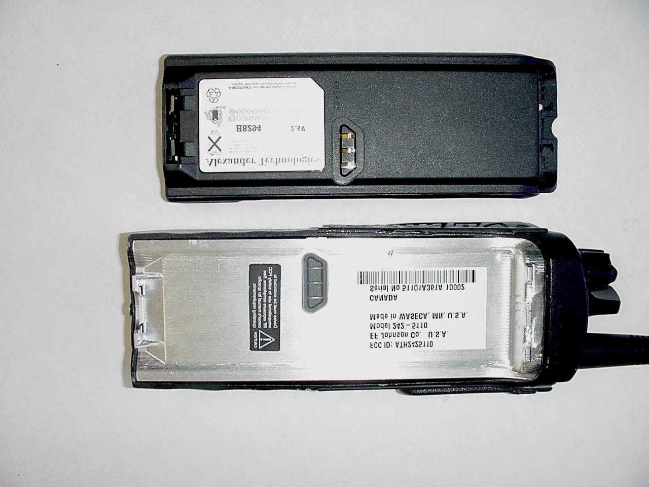
Click to zoom
Application Details
- Equipment Class
- TNF - Licensed Non-Broadcast Transmitter Held to Face
- Date of Grant
- Jan 15, 2002
- Application Purpose
- Original Equipment
- Date of Application
- Nov 01, 2001
- Equipment Note
- 242-5110
- Frequency Range
- 136.00000000 - 174.00000000
- Company
- E F Johnson Company
- Country
- United States
Documents & Files
Document Text
Text extracted from the exhibit documents filed with the FCC. Open a document above to read the original.
Users Manual
1 51xx Series FM Portable Radio Project 25, Conventional SMARTNET ™ , SmartZone ® PRELIMINARY OPERATING MANUAL LAND MOBILE PRODUCT WARRANTY - The manufacturer’s warranty statement for this product is available from your product supplier or from the E.F. Johnson Company, 299 Johnson Avenue, Box 1249, Waseca, MN 56093-0514. Phone (507) 835-6222. Copyright© 2001 by the E.F. Johnson Company E.F. Johnson Company, which was founded in 1923, designs, manufac- tures, and markets radio communication products, systems, and services worldwide. E.F. Johnson produces equipment for land mobile radio and mobiletelephone services which include business, industrial, government, public safety, and personal users. Viking Head/EFJohnson logo and Call Guard® are trademarks of the E.F. Johnson Company. SMARTNET™, SmartZone®, Call Alert™, Enhanced Private Conversation™, and Private Conversation II™ are trademarks of Motorola, Inc. All other company and/or product names used in this manual are trademarks and/or registered trademarks of their respective manufacturer. The IMBE™ voice coding technology embodied in this product is protected by intellectual property rights including patent rights of Digital Voice Systems, Inc. SAFETY TRAINING INFORMATION 4 SAFETY TRAINING INFORMATION WARNING This radio produces RF electromagnetic energy when transmitting and is designed and classified for “Occupational Use Only”. Radio equipment with this classification must be used only during the course of employ- ment by individuals aware of the hazards and the ways to minimize such hazards. This radio is NOT intended for use by the General Population in an uncontrolled environment. This radio has been tested and complies with FCC RF exposure limits for “Occupational Use Only”. In addition, it complies with the following standards and guidelines with regard to RF energy and electromagnetic energy levels and evaluation of such levels for exposure to humans: • FCC OET Bulletin 65 Edition 01-01 Suppl ement C, Evaluating Compliance with FCC Guidelines for Human Exposure to Radio Frequency Electromagnetic Fields. •American National Standards Institute (C95.1-1992), IEEE Standard for Safety Levels with Respect to Human Exposure to Radio Frequency Electromagnetic Fields, 3 kHz to 300 GHz. •American National Standards Institute (C95.3 -1992), IEEE Recom- mended Practice for the Measurement of Potentially Hazardous Electromagnetic Fields - RF and Microwave. CAUTION To ensure that your exposure to RF electromagnetic energy is within the FCC allowable limits for occupational use, always adhere to the following guidelines: •DO NOT operate the radio without the proper antenna attached. This may damage the radio and cause FCC RF exposure limits to be exceeded. The proper antenna is the antenna supplied with the radio by the manufacturer or an antenna specifically authorized by the manufacturer for use with this radio. SAFETY TRAINING INFORMATION 5 •DO NOT transmit more than 50% of total radio use time (50% duty cycle). Transmitting for more than 50% of the time can cause FCC RF exposure compliance requirements to be exceeded. This radio is transmitting when- ever Tx is indicated in the display. Pressing the PTT switch on the side usually causes the radio to transmit. •DO NOT use any accessories not specifically authorized by the E.F. Johnson Company for use with this radio such as batteries, speaker- microphones, belt clips, and antennas. The use of unauthorized accessories can cause FCC RF exposure compliance requirements to be exceeded. •ALWAYS keep the antenna and radio at least 2.54 cm (1.0 inch) away from your body when transmitting to ensure FCC RF exposure compliance requirements are not exceeded. The best transmission quality results when the antenna is at least 5 cm (2 inches) away from your mouth and angled slightly to one side. NOTE: The preceding information is provided to make you aware of RF exposure and what to do to ensure that this radio is operated within FCC RF exposure limits. Electromagnetic Interference/Usage Compatibility This device complies with Part 15 of the FCC rules. Operation is subject to the condition that this device does not cause harmful interference. In addition, changes or modification to this equipment no expressly approved by the E.F. Johnson Company could void the user’s authority to operate this equipment (FCC Rules, 47CFR Part 15.19). DO NOT operate it in areas that are sensitive to RF energy such as aircraft, hospitals, blasting sites, and fuel storage sites. Areas with potentially flammable atmospheres are usually, but not always, clearly posted. These may include gas stations, fuel and chemical storage and transfer stations, below deck on boats, and areas where the air contains flammable chemicals or particles such as grain dust or metal powders. Dispose of the nickel metal-hydride battery used by this radio in accordance with local regulations. DO NOT dispose of it in fire because it can explode. Also, do not short the terminals because it may become very hot. FEATURES 6 FEATURES General Features •Programmable for the following modes of operation: – Conventional analog – Conventional Project 25 (digital) – SMARTNET™/SmartZone® trunked (analog or digital) •Up to 16 zones with up to 16 channels each programmable (256 channels total) •Large liquid crystal display (LCD) with backlight •Nine programmable option switches (full keypad model) •Standard and radio-wide scan modes •Time-out timer •Power-up password access available to prevent unauthorized usage Conventional Features •Up to 256 channels or talk groups programmable •Repeater talk-around •Monitor mode selected by option switch •Carrier or Call Guard ® controlled squelch on analog channels •Penalty and conversation timers •Priority channel sampling when scanning •Busy channel lockout (transmit disable on busy) •SecureNet ™ or 460 secure communication available on analog channels, DES-OFB on Project 25 channels •Individual ID calls on Project 25 c…
Text truncated - open the document above for the full version.
Users Manual
Service Manualual 5100 SERIES PORTABLE DIGITAL/ANALOG VHF/UHF/800 MHz 7.2 VDC 5 & 1 W (VHF), 4 & 1 W (UHF), 3 W (800 MHz) Part No. 242-51xx-xxx First Printing September 2001 PRELIMINARY 51xx SERIES PORTABLE VHF/UHF/800 MHz PROJECT 25 (DIGITAL) AND ANALOG 7.5 VDC 5 & 1 W (VHF), 4 & 1 W (UHF), 3 W (800 MHz) Part No. 242-51xx-xxx Copyright© 2001 by the E.F. Johnson Company The E.F. Johnson Company, which was founded in 1923, provides wireless communication systems solutions for public safety, government, and commercial customers. The company designs, manufactures, and markets conventional and trunked radio systems, mobile and portable subscriber radios, repeaters, and Project 25 digital radio products. E.F. Johnson is a wholly owned subsidiary of Transcrypt International, Inc. Viking Head/EFJohnson logo, Call Guard ® , PCTrunk ™ , and PCTune ™ are registered trade- marks of the E.F. Johnson Company. SMARTNET ™ , SmartZone ® , SecureNet ™ , Call Alert ™ , Enhanced Private Conversation ™ , and Private Conversation II ™ are trademarks of Motorola, Inc. All other company and/or product names used in this manual are trademarks and/or reg- istered trademarks of their respective manufacturer. The IMBE™ voice coding technology embodied in this product is protected by intellectual property rights including patent rights of Digital Voice Systems, Inc. Information in this manual is subject to change without notice. TABLE OF CONTENTS ii September 2001 Part No. 001-5100-001 TABLE OF CONTENTS 1GENERAL INFORMATION 1.1SCOPE OF MANUAL. . . . . . . . . . . . . . . . . . . .1-1 1.2TRANSCEIVER DESCRIPTION. . . . . . . . . . .1-1 General . . . . . . . . . . . . . . . . . . . . . . . . . . . . . . . . 1-1 Analog/Digital Operation. . . . . . . . . . . . . . . . . . 1-1 Operating Protocols . . . . . . . . . . . . . . . . . . . . . . 1-1 18-Key/6-Key Models . . . . . . . . . . . . . . . . . . . . 1-1 Systems, Channels, and Zones . . . . . . . . . . . . . . 1-1 Secure Communication . . . . . . . . . . . . . . . . . . . 1-2 Programming . . . . . . . . . . . . . . . . . . . . . . . . . . . 1-2 Alignment. . . . . . . . . . . . . . . . . . . . . . . . . . . . . . 1-2 1.3PRODUCT WARRANTY . . . . . . . . . . . . . . . . .1-2 1.4PART NUMBER BREAKDOWN. . . . . . . . . . .1-3 1.5TRANSCEIVER IDENTIFICATION . . . . . . . .1-3 1.6ACCESSORIES. . . . . . . . . . . . . . . . . . . . . . . . .1-3 1.7FACTORY CUSTOMER SERVICE . . . . . . . .1-4 1.8FACTORY RETURNS . . . . . . . . . . . . . . . . . . .1-5 1.9REPLACEMENT PARTS. . . . . . . . . . . . . . . . .1-5 1.10 INTERNET HOME PAGE. . . . . . . . . . . . . . . . .1-5 2OPERATION 2.1FEATURES. . . . . . . . . . . . . . . . . . . . . . . . . . . . .2-1 General Featu res . . . . . . . . . . . . . . . . . . . . . . . . 2-1 Conventional Features . . . . . . . . . . . . . . . . . . . . 2-1 SMARTNET/SmartZone Features. . . . . . . . . . . 2-1 2.2OPTION SWITCH FUNCTIONS. . . . . . . . . . .2-1 2.3CONTROLS AND DISPLAY. . . . . . . . . . . . . .2-2 Front Panel Controls. . . . . . . . . . . . . . . . . . . . . . 2-2 Top Panel Controls. . . . . . . . . . . . . . . . . . . . . . . 2-3 Side Controls . . . . . . . . . . . . . . . . . . . . . . . . . . . 2-4 Display . . . . . . . . . . . . . . . . . . . . . . . . . . . . . . . . 2-4 2.4GENERAL OPERATION . . . . . . . . . . . . . . . . .2-5 Introduction . . . . . . . . . . . . . . . . . . . . . . . . . . . . 2-5 Turning Power On and Setting Volume. . . . . . . 2-5 Power-Up Password . . . . . . . . . . . . . . . . . . . . . . 2-5 Backlight. . . . . . . . . . . . . . . . . . . . . . . . . . . . . . . 2-5 Option Switches . . . . . . . . . . . . . . . . . . . . . . . . . 2-6 Keypad Lock . . . . . . . . . . . . . . . . . . . . . . . . . . . 2-6 Low Battery Indication. . . . . . . . . . . . . . . . . . . . 2-6 Channel and Zone Selection. . . . . . . . . . . . . . . . 2-6 Home Zone. . . . . . . . . . . . . . . . . . . . . . . . . . . . . 2-7 Time-Out Timer . . . . . . . . . . . . . . . . . . . . . . . . . 2-7 Tone Enable/Disable . . . . . . . . . . . . . . . . . . . . . 2-7 Transceiver Operating Modes . . . . . . . . . . . . . . 2-7 Secure Communication . . . . . . . . . . . . . . . . . . . 2-8 2.5SCANNING. . . . . . . . . . . . . . . . . . . . . . . . . . . . .2-8 Introduction . . . . . . . . . . . . . . . . . . . . . . . . . . . . 2-8 Standard Scanning . . . . . . . . . . . . . . . . . . . . . . . 2-8 Radio Wide Scanning . . . . . . . . . . . . . . . . . . . . . 2-8 Scan Resume Delay . . . . . . . . . . . . . . . . . . . . . . 2-9 Standard Mode Scan List . . . . . . . . . . . . . . . . . . 2-9 Radio Wide Mode Scan List. . . . . . . . . . . . . . . . 2-9 Determining Which Channels are in Scan List. . 2-9 Nuisance Channel Delete . . . . . . . . . . . . . . . . . . 2-9 Programming a Scan List . . . . . . . . . . . . . . . . . . 2-9 2.6CONVENTIONAL FEATURES . . . . . . . . . . .2-10 Introduction. . . . . . . . . . . . . . . . . . . . . . . . . . . . 2-10 Display Mode Selection . . . . . . . . . . . . . . . . . . 2-10 Monitoring Before Transmitting. . . . . . . . . . . . 2-10 Monitor Mode. . . . . . . . . . . . . . . . . . . . . . . . . . 2-11 Busy Channel Lockout . . . . . . . . . . . . . . . . . . . 2-11 Call Guard Squelch. . . . . . . . . . . . . . . . . . . . . . 2-11 Penalty Timer . . . . . . . . . . . . . . . . . . . . . . . . . . 2-12 Conversation Timer . . . . . . . . . . . . . . . . . . . . . 2-12 Repeater Talk-Around . . . . . . . . . . . . . . . . . . . 2-12 Power Output Select . . . . . . . . . . . . . . . . . . . . . 2-13 Emergency Mode (Conventional). . . . . . . . . . . 2-13 Conventional Mode Scanning. . . . . . . . . . . . . . 2-13 Priority Channel Sampling . . . . . . . . . . . . . . . . 2-14 Placing and Receiving Standard Conventional Calls . . . . . . . . . . . . . . . . . . . . . . . . . . . . . . . 2-14 DTMF/ANI Signaling. . . . . . . . . . . . . . . . . . . . 2-15 Project 25 Mode Features. . . . . . . . . . . . . . . . . 2-15 Conventional …
Text truncated - open the document above for the full version.
Users Manual
TRANSCEIVER PROGRAMMING 3-18 September 2001 Part No. 001-5100-001 Figure 3-4 Conventional Project 25 Digital Channel Screen 3.5.7 CONVENTIONAL PROJECT 25 (DIGITAL) CHANNEL SCREEN PARAMETERS The following parameters are programmed in the conventional Project 25 digital channel screen shown in Figure 3-4. Refer to Section 2.6.16 for more infor- mation on Project 25 operation. The Selected Channel, Channel Type, Transmit Power, and Transmit Time-Out Parameters are programmed the same as with analog channels described in preceding section. Talk Groups This selects the Project 25 talk group that is assigned to the channel. The talk group programs the talk group ID, strapping mode, and encryption key address. Talk groups for Project 25 channels are programmed in the Conventional System Talk Group screen described in Section 3.5.4. Strapped to Selected Group - If this parameter is selected, the talk group on that channel is always the selected talk group and cannot be changed. Radio List Selectable - If this parameter is selected, the talk group may be changed by the radio operator using the (Digital) Talk Group Select option switch. Busy Channel Lockout Off = disabled, Noise = transmit disallowed if carrier is detected, NAC = transmit allowed only if correct NAC is detected (Section 2.6.5). Access Codes Programs the transmit and receive NAC (Network Access Code). These codes can be 0-4095. Refer to Section 2.6.16 for more information. Mixed Mode A mixed mode that allows both analog and Project 25 operation to be programmed on a channel can be enabled on the Project 25 channel screen (see Figure 3-4). This mode is programmed as follows: Enable - Checking this box selects mixed analog/Project 25 operation on the channel. Tx Analog - Checking this box selects Transmit = analog/Receive = Project 25. If it is not checked, the opposite is selected. When the mixed mode is selected, the channel modulation, coded squelch, and ANI signaling param- eters for the analog channel must then be programmed. TRANSCEIVER PROGRAMMING 3-19 September 2001 Part No. 001-5100-001 These parameters are programmed the same as described in Section 3.5.6. 3.6 PROGRAMMING SMARTNET/SMARTZONE SYSTEMS AND CHANNELS 3.6.1 INTRODUCTION To program SMARTNET and SmartZone systems and channels, proceed as follows: 1. Program the SMARTNET/SmartZone radio-wide information as described in Section 3.4. 2. To create a new SMARTNET/SmartZone system, select the Systems > Add Systems in the menu bar (see Section 3.1.11). Up to sixteen systems of any type can be programmed as described in Section 1.2.5. 3. Program the SMARTNET/SmartZone system infor- mation as described starting in the next section. Make sure the desired SMARTNET or SmartZone system is displayed by clicking it in the left pane or selecting it in the Window menu in the menu bar (see Section 3.1.9). Then program the channels as described starting in Section 3.6.8. 3.6.2 SMARTNET/SMARTZONE SYSTEM GENERAL SCREEN The preceding SMARTNET/SmartZone System General screen programs the following parameters: Restricted Access Change System ID Button - Displays the Change System ID screen which is used to enter the system ID of the system. This ID is entered as a hexadecimal number from 0-9 and A-F. Valid numbers are from 0001-FFFF. The system ID corresponding to the desired ID must also be located in the “key” subdi- rectory of the program file. System ID - Read-only field which shows the ID of the system currently being edited. Splinter Channels When splinter channels are enabled, the receive and transmit frequencies are 12.5 kHz lower than the normal frequencies. Splinter channels are used only as required in the Mexico and Canada border areas for frequencies between 806 and 820.975 MHz. Channel Modulation When “Wideband” is enabled, the radio operates with a 4 kHz maximum deviation between 821.000 and 824.975 MHz and 5 kHz maximum deviation for all other frequencies. When it is disabled, deviation is 5 kHz with all frequencies. System Lists Button This button displays the screens used to program the various per system lists. Refer to Section 3.6.7 for more information on these lists. Dynamic Regrouping Enable For This System - When this box is checked, a dynamic regrouping channel is enabled. This is a SMARTNET channel which has the corresponding talk group dynamically set by the dispatcher. Zone - The physical zone containing the dynamic regrouping channel. The value is selected on the Channel Parameters screen. TRANSCEIVER PROGRAMMING 3-20 September 2001 Part No. 001-5100-001 Channel - The physical channel used for dynamic regrouping. The value is selected on the Channel Parameters screen. Affiliation Type Automatic - The radio immediately affiliates with the central controller as soon as it is turned on and auto- matically re-affiliates each time the talk group is changed. On PTT - The radio affiliates with the central control- ler only when the PTT switch is pressed. Time-Out Timer This programs the time-out timer setting for the system. It can be programmed for 0 min, 15 sec up to 3 min, 45 sec or it can be disabled (see Section 2.4.10). ISW Delay Increasing or decreasing this value changes the transmission timing of ISWs relative to the reception of OSWs. 3.6.3 SMARTNET/SMARTZONE SYSTEM OTHER ID’S SCREEN The SMARTNET/SmartZone Other ID’s screen is shown above, and it programs the following parameters. Individual ID - Uniquely identifies the radio on a par- ticular system. Each radio must have a different Unit ID. Valid Unit IDs are from 1-63535. Connect Tone - The tone expected by the controller on the traffic channel to verify that a subscriber trans- mission is occurring. This tone should be set the same as it is in the controller. Encryption Key IDs Programs SecureNet Encryption ID selection that is used in all except group calls. System Wide - Key used for system-wide calls (typically originated by the dispatcher). Failsoft - Key used in failsoft conditions (see Section 2.7.…
Text truncated - open the document above for the full version.
Users Manual
CIRCUIT DESCRIPTION 4-11 September 2001 Part No. 001-5100-001 4.4.6 UART The UART performs parallel to serial and serial to parallel conversion. The serial format used is a 9-bit format with start and stop bits. The serial transmission speed is 19200 bps. The UART appears as eight regis- ters visible in the I/O space of the DSP starting at every multiple of 0008h from 0000h to 07FFh. U11 performs the address decoding by selecting the UART when both IS* and A15 are low. Crystal Y2 along with the internal oscillator of the UART provides the clock required to generate the correct bit rate on the serial output of the UART. When the UART receives a new serial word or is ready to accept a new word to send from the DSP, it generates an interrupt on INTRN. This pin is connected to one of the hardware interrupt lines on the DSP. The DSP responds by reading the status register in the UART and by answering accordingly. 4.4.7 ADSIC The ADSIC is a complex custom IC which performs many analog-to-digital, digital-to-analog, and purely digital functions as previously described. The ADSIC has four internal registers accessible by the DSP. They are selected through the use of address lines A15, A14, A13, A2, A1, A0, IS* (IS* needs to be inverted with U4 to be compatible with the logic level required by the ADSIC), RD*, and WR*. Two of these registers are read-only while the two others are write- only. Therefore, they can be accessed as two locations in the I/O spaces. Due to the decoding performed, those locations appear at the following addresses: Fxx0h, Fxx1h, Fxx8h, Fxx9h, Exx0h, Exx1h, Exx8h, and Exx9h. Crystal Y1 along with the internal oscillator in the ADSIC provide a 20 MHz clock. This clock signal is used internally by the ADSIC and is also multiplied by two to provide a 40 MHz clock to the DSP. The frequency of the clock can be electronically shifted a small amount by controlling varicap D1 through the OSCW pin (U3-97). This removes interference created on some channels by the clock. The ADSIC and DSP exchange the sampled receive data and the sampled VCO modulation signal through a serial port. This serial port consists of pins SCKR*, RFS, RxD, TxD, SCKT, and TFS on the ADSIC. U21 and U1 modify the relative phase of TxD and TFS to be compatible with the timing required on the serial port of the DSP. SDO is the output of the internal speaker DAC. MAI is the input of the internal microphone attenuator and is followed by the microphone ADC. The ADSIC is configured partially by the DSP through its data and address bus (see preceding). However, most of the configuring is provided through an SPI compatible serial bus. This SPI serial bus consists of pins SEL*, SPD, and SCLK. The other side of this bus is connected to the controller on the Keypad Board. 4.5 KEYPAD BOARD 4.5.1 INTRODUCTION The Keypad Board contains a microcontroller, LCD Display, Display Driver, Audio circuits, and Power supply. The Keypad Board interfaces with the Digital board via J4, with the Top Control rigid flex circuit via J13, and with the side buttons, PTT switch, and accessory connector through J5. 4.5.2 FUNCTIONAL DESCRIPTION The microcontroller provides an interface between the hardware and the DSP (on the Digital Board). When the user presses or rotates a control such as the channel selector switch, a side option or PTT switch, or a keypad key, the microcontroller signals the change to the DSP. Conversely, when the DSP needs to change the display or an LED, it signals the microcontroller which then performs the action. The microcontroller also controls peripheral ICs such as the synthesizer, reference oscillator, display, and ADSIC. The microcontroller uses a serial bus to commu- nicate with the DSP and another RS232 bus to communicate with the side port connector. The side connector bus is used for external communication with a computer running the programming or tuning soft- ware. Finally, the microcontroller maintains certain operating parameters in the associated EEPROM which is controlled via a two-wire serial bus. DIGITAL BOARD (CONT’D) CIRCUIT DESCRIPTION 4-12 September 2001 Part No. 001-5100-001 4.5.3 MICROCONTROLLER The microcontroller is a Motorola M68HC08XL36 chip. It includes 28K bytes of internal ROM memory and 1K byte of internal SRAM. It does not have an external bus and therefore cannot access any external program memory. The clock to the microcontroller is provided by Y1 and an internal oscillator. The frequency of the clock can be slightly offset by polarizing the base of Q3 through software control. This prevents RF inter- ference on some channels caused by the clock. The microcontroller contains an SPI-compatible synchronous serial bus. This bus consists of pins MISO (U1-53), MOSI (U1-52), SPSCK (U1-50), and a chip enable for each device with which it communi- cates. The devices which communicate with the microcontroller through this bus are as follows: •Top Display driver chip (Top Display board) •Front Display driver chip (Digital board) •ADSIC chip (Digital board) •Reference Oscillator (RF Board) •Front-End DAC (RF Board) •Synthesizer chip (RF Board) •Optional DES board. The microcontroller communicates with the DSP chip (Digital board) through a custom serial bus. This serial port includes pins PTA3 (U1-8), PTA4 (U1-9), PTA5 (U1-10), PTA6 (U1-11), and PTA7 (U1-12). The microcontroller uses its SCI asynchronous serial bus for external communication with a computer running programming or tuning software. The SCI pins RxD (U1-42) and TxD (U1-43) are connected to RS232 driver receiver U5. The other signals of a stan- dard RS232 computer port (DSR, DTR, CTS, RTS) are generated using microcontroller input/outputs. The RS232 driver U5 converts signals from a logic level of 0 and 5 V to a logic level of –10 and +10V. The chip contains an internal charge pump to generate –10V and +10V from the 5V power supply. The RS232 chip can be put in standby mode by leaving the line K/F-RS232* floating. This line is conn…
Text truncated - open the document above for the full version.
Cover Letter(s)
Waseca Office: E.F. Johnson Company • 299 Johnson Ave., P.O. Box 1249 • Waseca, MN 56093-0514 • 800-328-3911 • 507-835-6222 • Fax 507-835-8356 www.efjohnson.com October 26, 2001 Federal Communications Commission EQUIPMENT AUTHORIZATION BRANCH 7435 Oakland Mills Road Columbia, MD 21046 Re: Programming Capability Dear FCC Representative; Reference part 90.203(e), frequency programming capability. The end user will not be able to program the channel frequencies. A service shop or authorized agent using a special programming cable and computer software can program the allowed TX/RX frequencies. The end user can only select from the preprogrammed channels using the channel select knob. The software and programming cable are not available to the end user. Sincerely, David Hattey President and General Manager E.F. Johnson Co.
Cover Letter(s)
Waseca Office: E.F. Johnson Company • 299 Johnson Ave., P.O. Box 1249 • Waseca, MN 56093-0514 • 800-328-3911 • 507-835-6222 • Fax 507-835-8356 www.efjohnson.com October 26, 2001 Federal Communications Commission EQUIPMENT AUTHORIZATION BRANCH 7435 Oakland Mills Road Columbia, MD 21046 Re: Agent Authorization To Whom It May Concern: E. F. Johnson Co. hereby authorizes Rhein Tech Laboratories, Inc. (RTL), 360 Herndon Parkway, Suite 1400, Herndon, VA 20170 to act as agent. APPLICANT ANTI-DRUG ABUSE CERTIFICATION: In signing this letter, Applicant certifies that, in the case of an individual applicant, he or she is not subject to a denial of federal benefits, that includes: FCC benefits, pursuant to Section 5301 of the Anti-Drug Abuse Act of 1988, 21 U.S.C. 853(a), or, in the case of a non-individual applicant. No party to the application is subject to a denial of federal benefits, that includes FCC benefits, pursuant to that section. For the definition of a “party” for these purposes, see 47 CFR 1.2002(b). Sincerely, David Hattey President and General Manager E.F. Johnson Co.
Cover Letter(s)
Waseca Office: E.F. Johnson Company • 299 Johnson Ave., P.O. Box 1249 • Waseca, MN 56093-0514 • 800-328-3911 • 507-835-6222 • Fax 507-835-8356 www.efjohnson.com October 26, 2001 Federal Communications Commission 7435 Oakland Mills Road Columbia, MD 21046 To Whom It May Concern: The following information is to be held confidential pursuant of 47 CFR Part 0 §0.457 and Section 552(b)(4) of the Freedom of Information Act, because the information provided contains trade secrets and proprietary. If made public, the information might be used to the disadvantage of the applicant in the market place. • Schematics • Product Description • Block Diagram • Bill of Materials (Parts List) Sincerely, David Hattey President and General Manager E. F. Johnson Co.
Cover Letter(s)
Engineering and Testing for EMC and Safety Compliance 360 Herndon Parkway, Suite 1400 Herndon, VA 20170 Phone: 703-689-0368; Fax: 703-689-2056; Metro: 703-471-6441 November 6, 2001 Federal Communications Commission 7435 Oakland Mills Road Columbia, MD 21046 Re: FCC ID: ATH2425110 / EA649893 To Whom It May Concern: The 731 form lists Parts 22 and 90. This information is incorrect. It should only be FCC Part 90. Best Regards, Melissa Carter [email protected] Rhein Tech Laboratories, Inc.
Cover Letter(s)
To: Bruno Clavier, null From: Martin Perrine [email protected] FCC Application Processing Branch Re: FCC ID ATH2425110 Applicant: E F Johnson Company Correspondence Reference Number: 21627 731 Confirmation Number: EA649893 In regards to your recent application referenced above we kindly request that you provide the following additional information. SAR 1) Clarification if there are three or four antennas available for use with this radio. The SAR test reports discusses three antennas however table 1-2 of the EMC test report mentions a fourth antenna. If appropriate provide SAR data using the fourth antenna. The test report was revised. There are only 3 antennas available for use with this radio. 2) Clarification if there are one or two batteries available for use with this radio. The SAR test reports discusses only one battery however table 1-2 of the EMC test report mentions a second battery. If appropriate provide SAR data using the second battery. Both batteries are mechanically and electrically identical. 3) Please provide print outs from dielectric property measurement equipment for all measured liquids. Please see SAR correspondence 4) Z axis SAR scan data for highest SAR points for each test, if available. Please see SAR correspondence 5) Worst case SAR analysis justifying use of the extrapolated probe conversion factors. Please see SAR correspondence Filename: RTL Correspondence 21627 Directory: F:\REPORTS\E Section\EF Johnson\2001258 QRTL01- 252\FCC\1-10-02 Template: C:\WINDOWS\Profiles\mcarter\Application Data\Microsoft\Templates\Normal.dot Title: To: Bruno Clavier, null Subject: Author: Systems Administrator Keywords: Comments: Creation Date: 01/10/2002 3:17 PM Change Number: 1 Last Saved On: 01/10/2002 3:20 PM Last Saved By: Systems Administrator Total Editing Time: 4 Minutes Last Printed On: 01/10/2002 4:45 PM As of Last Complete Printing Number of Pages: 1 Number of Words: 203 (approx.) Number of Characters: 1,161 (approx.)
Cover Letter(s)
To: Bruno Clavier, Rhein Tech Laboratories Inc. From: Martin Perrine [email protected] FCC Application Processing Branch Re: FCC ID ATH2425110 Applicant: E F Johnson Company Correspondence Reference Number: 21681 731 Confirmation Number: EA649893 In regards to your recent application referenced above we kindly request that you provide the following additional information. 1) Bandwidth justification for 8 KHz and 16 KHz emissions. The emission for C4FM modulation is 8.1kHz per EIA/TIA-102.BAAA standard. The 99% emission bandwidth was measured in accordance with EIA/TIA-102.CAAA section 2.2.5 Modulation emission spectrum. The plot was provided in the test report, Plot-5-1 page 16. The necessary bandwidth for analog 12.5 kHz and 25kHz emission were calculated per Carson's rules in section 1.3 of the test report. 2) DC currents and voltages in the final am…
Text truncated - open the document above for the full version.
Contact Information
Applicant
Karthik Rangarajan(SR VP Engineering)
Technical Contact
Rhein Tech Laboratories Inc.Bruno Clavier
[email protected]703-689-0368
360 Herndon Parkway · Herndon, Virginia · United States
Non-Technical Contact
Rhein Tech Laboratories, Inc.Melissa Carter
[email protected]703-689-0368
Test Firm
Rhein Tech Laboratories, Inc.Rick McMurray
Technical Specifications
| # | Rule Parts | Frequency Range | Power Output | Emission | Tolerance |
|---|---|---|---|---|---|
| 6 | 9 | 136 MHz - 174 MHz | 1.2 W | 8K10F1E | 2.5 ppm |
Other Applications from E F Johnson Company
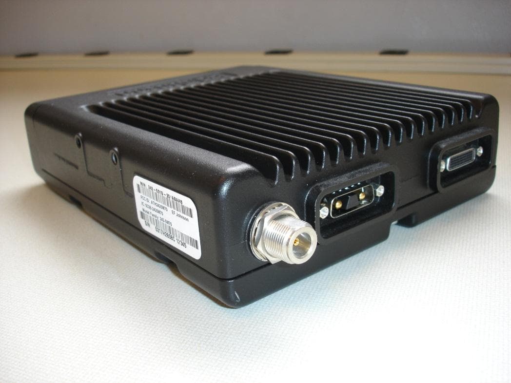
ATH2425M80
Nov 19, 2015DUAL BAND VHF AND 700/800 MHz MOBILE TRANSCEIVER
Equipment Class
TNB - Licensed Non-Broadcast Station Transmitter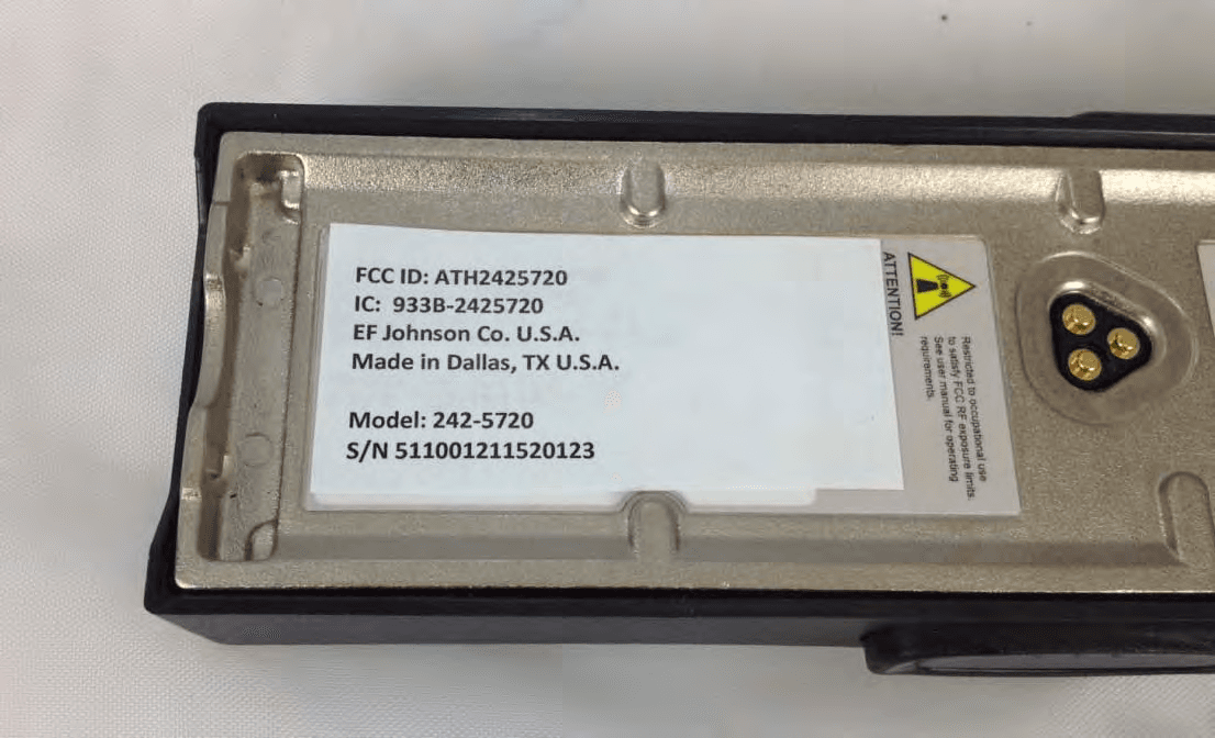
ATH2425720
Sep 30, 2012VP 600 UHF Land Mobile Radio Transceiver
Equipment Class
TNF - Licensed Non-Broadcast Transmitter Held to Face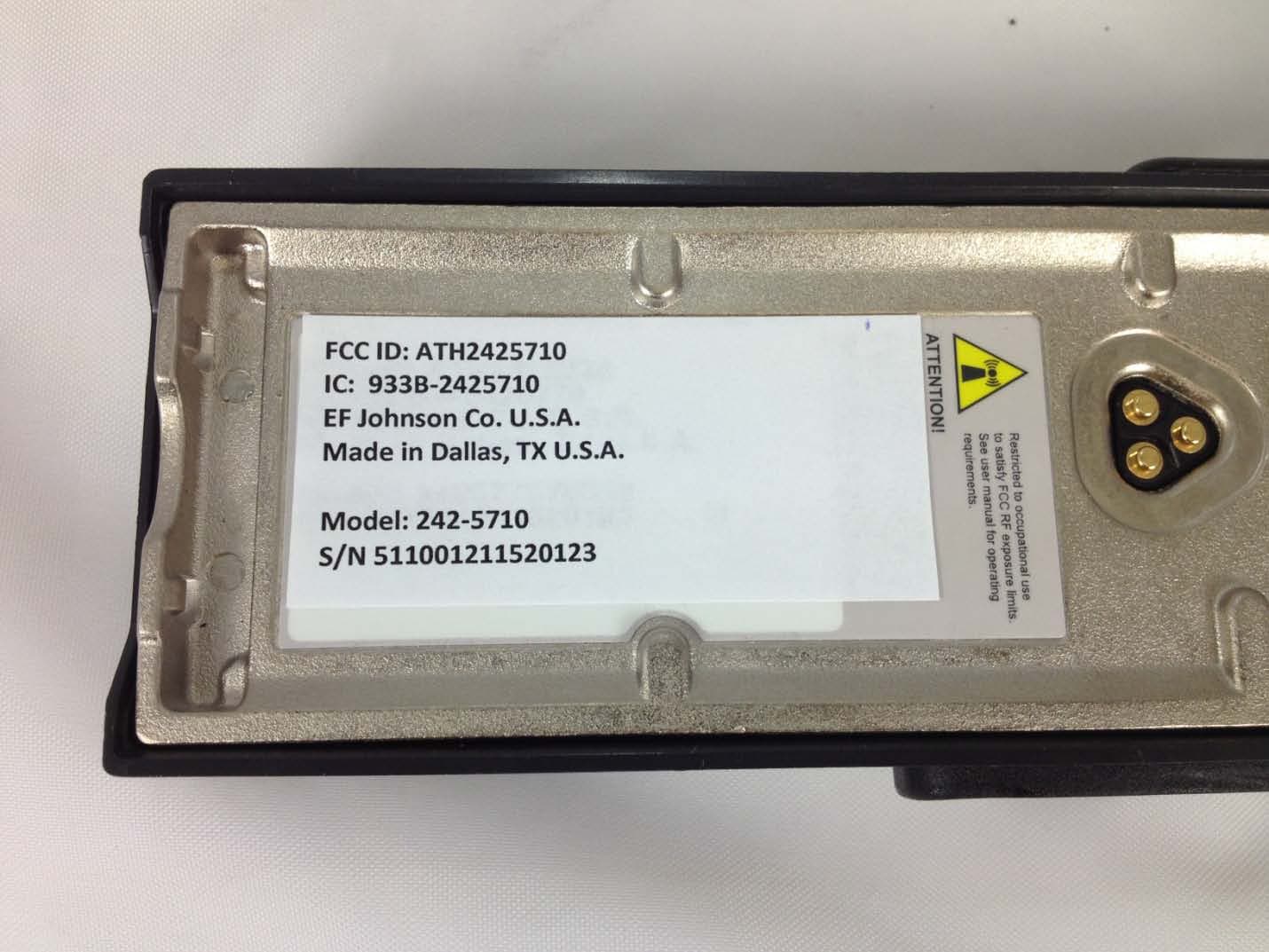
ATH2425710
Sep 16, 2012Portable VHF Push-To-Talk (PTT) Radio Transceiver
Equipment Class
TNF - Licensed Non-Broadcast Transmitter Held to Face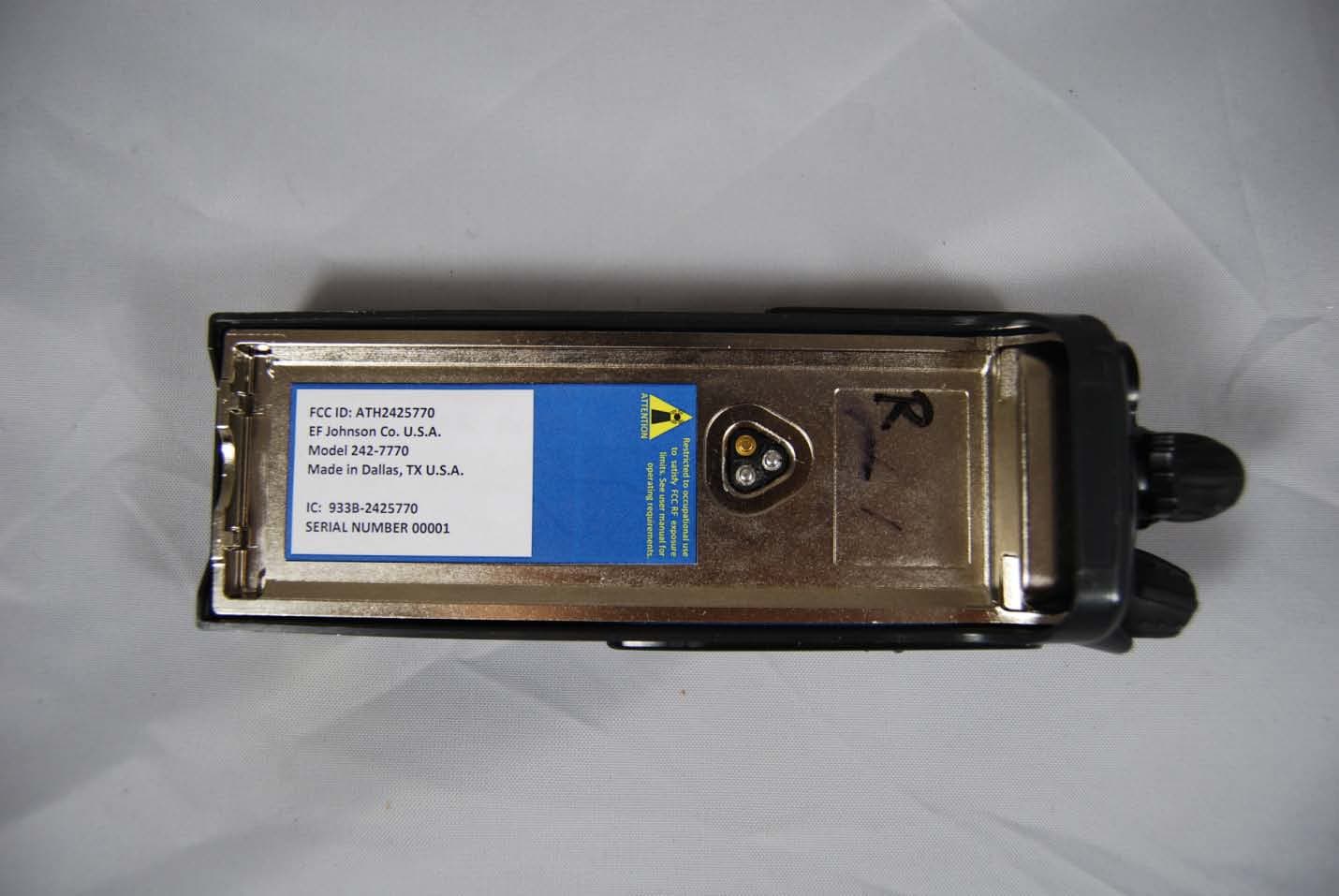
ATH2425770
Feb 09, 2012Vantage 700/800 MHz Portable Radio
Equipment Class
TNF - Licensed Non-Broadcast Transmitter Held to Face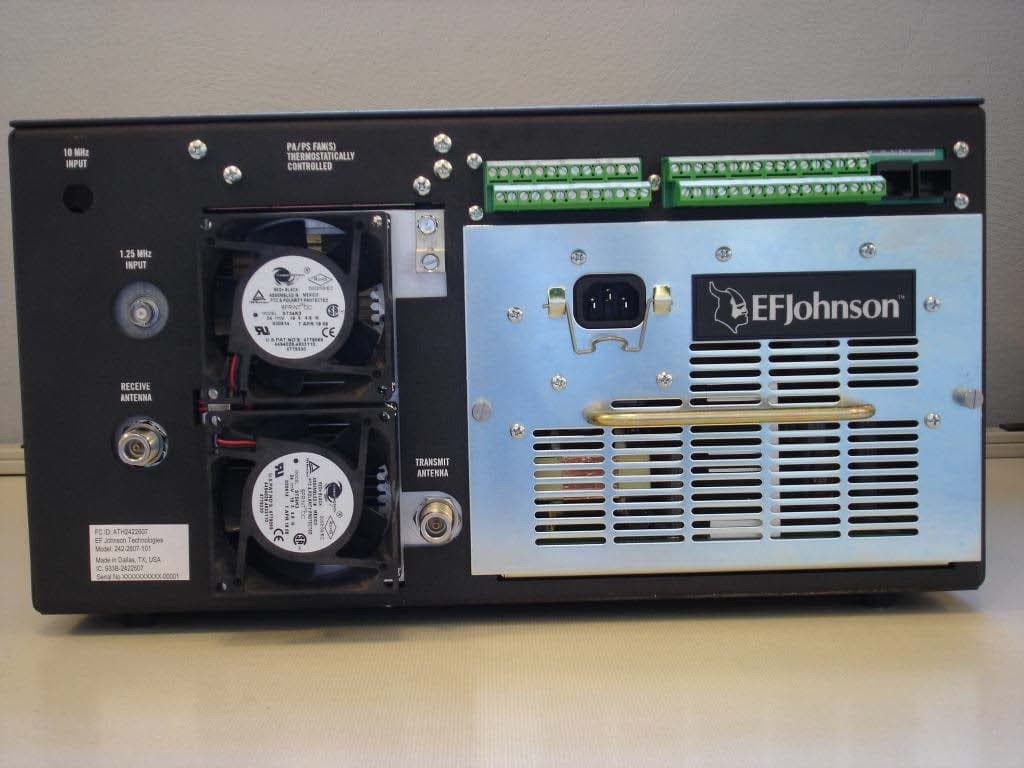
ATH2422607
Mar 07, 2010700 MHz LAND MOBILE REPEATER
Equipment Class
TNB - Licensed Non-Broadcast Station Transmitter