ATH2425770Vantage 700/800 MHz Portable Radio
E F Johnson Company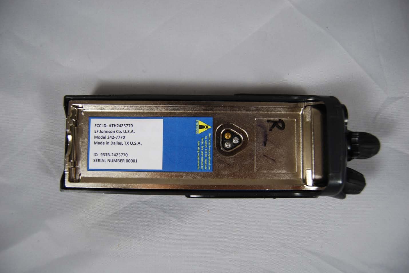
Click to zoom
Application Details
- Equipment Class
- TNF - Licensed Non-Broadcast Transmitter Held to Face
- Date of Grant
- Feb 09, 2012
- Application Purpose
- Original Equipment
- Date of Application
- Feb 08, 2012
- Equipment Note
- Vantage 700/800 MHz Portable Radio
- Frequency Range
- 851.00000000 - 869.00000000
- Company
- E F Johnson Company
- Country
- United States
Documents & Files
Document Text
Text extracted from the exhibit documents filed with the FCC. Open a document above to read the original.
Users Manual
Draft 2/8/12 Viking Portable Radio Service Manual2-1 SECTION Section 2Battery, Accessory and Disassembly Information 2.1Battery Information 2.1.1Battery Removal / Installation To remove the battery from the radio for recharging or replacement, first turn the radio off. Then press the release button (see Figure 2.1) and rotate the battery upward to the approximate point shown and remove it from the radio. Figure 2.1Battery Removal Battery Release Button NEEDS TO BE REPLACED Draft 2/8/12 2-2Viking Portable Radio Service Manual Battery, Accessory and Disassembly Information 2.1.2Preventing Loss of Encryption Keys during Battery Change If Infinite Key Retention is not programmed, the radio must be connected to a constant power source to preserve the encryption keys in memory. Storage capacitors maintain the supply voltage (and these keys) for approximately 3.5 minutes to allow the battery to be changed. Therefore, when changing the battery of a radio containing keys, make sure to reattach another battery within 3.5 minutes. 2.1.3Battery Specifications Table 2.1 contains specifications for batteries. For current advertised specifications, refer to the specification sheet available from your sales representative. Values are typical and are subject to change without notice. 2.1.4Battery Charging The following considerations apply to all rechargeable batteries: • Be sure to carefully read the instructions for operation of the battery charger, and follow all of them carefully. • Do not charge the battery with radio power on. • If batteries are not in service (i.e., in storage) be sure to recharge them at least every 12 months. • Be sure, especially when using Nickel Metal-Hydride (NiMH) batteries, to put new batteries (or batteries that have been inactive for a significant time) through at least three full charge/discharge cycles initially. Otherwise the batteries may not provide the full number of operating hours for which they are rated. Do not transmit in close proximity to the charger base. Do not expose the charger base to high level RF signals while a battery is being charged because this may cause a charger fuse to blow (especially in the UHF range). Radios programmed for SMARTNET/ SmartZone operation, for example, may affiliate while in the charger which causes them to key automatically. Therefore, do not leave radio power on while charging. Table 2.1Viking Portable Portable Radio Battery Specifications Battery TypeDimensions (HxWxD)WeightApproximate Life (5/5/90) Ultra-High Capacity Lithium Ion 6.5 x 2.3 x .78 inches (165.1 x 58.42 x 19.8 mm) 8.1 oz. (60.66213 kg)12 hours CAUTION ! Draft 2/8/12 Viking Portable Radio Service Manual2-3 Battery, Accessory and Disassembly Information 2.1.4.1Charging Li-Ion Batteries The Li-Ion (Lithium-Ion) battery can be charged separately or while attached to the radio. When it is charged while attached to the radio, radio power should be turned off. NoteThe Li-P battery can only be charged in an approved battery charger. Charging lithium batteries in nickel only chargers can result in overcharging the batteries and can damage the cells through swelling. With radio power off, charge current begins at a set level and gradually decreases as the battery is charged. When the charge current decreases to 100Ma, all charge current is automatically turned off and the charger switches to Ready mode. This is indicated by a green Ready indication. No trickle charge current is applied. If radio power is left on, the initial charging process is as described above. However, because the radio standby current is in excess of 100mA, the charge current never decreases to the 100 mA charge cutoff threshold. The charger continues to charge until the four-hour timeout is reached, then automatically switches to Ready mode. If the radio is left with power on, the battery will slowly discharge. If the battery discharges to a set voltage level (7.8V to 8.0V, depending upon battery type) the charger will automatically enter recharge mode, and repeat the previously described recharge process. In summary, if the Li-Ion battery is left in the radio and charged while the radio power is left on, the following cycle s repeated: the radio charges (approximately four hours), then switches to Ready mode (approximately two to three hours), then switches back to charging to begin a new cycle. 2.1.5Battery Care Do not incinerate a battery pack because of the risk of explosion. Also, do not short circuit the terminals because the battery pack and the object causing the short may become very hot. Do not disassemble or modify a battery pack. Proper battery care enhances the useful life of the battery. The battery should be recharged as soon a practical after the low battery indication appears. Follow the charging instructions in the manual included with the charger. When the battery fails to hold a charge or provides only a very short operating time, it must be replaced with a new unit. Specified battery life is approximately 10-to-12 hours of service before recharging is required. This time assumes that 5% of the time is spent transmitting, 5% in the receive unsquelched mode, and 90% in the receive squelched mode. The operating time may be less if more time is spent in the transmit or unsquelched modes, or if the battery is not fully charged or its capacity has deteriorated. Be sure to dispose of the nickel metal-hydride (NiMH) battery pack in accordance with local waste regulations. WARNING ! Draft 2/8/12 2-4Viking Portable Radio Service Manual Battery, Accessory and Disassembly Information 2.2Belt Clip Installation Remove the battery and slide the beltclip into the slot on the battery until it locks into place (see Figure 2.2). To remove the beltclip, squeeze the tab on the end of the beltclip and slide the beltclip out. Figure 2.2Belt Clip Installation 2.3Accessory Installation To connect an accessory such as a speaker-microphone to the radio, refer to Figure 2.3 and proceed as follows: 1Remo…
Text truncated - open the document above for the full version.
Users Manual
Viking Portable 600™ Radio Operating Manual for the VP600 Model 2 Radio Project 25 Conventional and Trunked SmartNet ® /SmartZone ® Analog and Digital Conventional Part Number 002-0600-04500 March 2012 Preliminary Draft 3/9/12 Preliminary Draft 3/9/12 Copyright © 2012 by EF Johnson Technologies, Inc. The EFJohnson Technologies logo, Armada ™ , Trunked IP25 ™ , and Call Guard ® are trademarks of EF Johnson Technologies, Inc. All other company and/or product names used in this manual are trademarks and/or registered trademarks of their respective manufacturers. Information in this manual is subject to change without notice. Viking Portable 600 Radio Operating Manual March 2012 Preliminary Draft 3/9/12 Preliminary Draft 3/9/12 Viking Portable 600 Radio Operating Manual i Table of Contents Viking Portable 600 Radio Operating Manual March 2012 Safety Requirements ix 1Features1-1 General Features . . . . . . . . . . . . . . . . . . . . . . . . . . . . . . . . . . . . . . . . . . . . . . . . . . . . . . . . . . . . . . . 1-1 Conventional Features . . . . . . . . . . . . . . . . . . . . . . . . . . . . . . . . . . . . . . . . . . . . . . . . . . . . . . . 1-3 Project 25 Trunked Features. . . . . . . . . . . . . . . . . . . . . . . . . . . . . . . . . . . . . . . . . . . . . . . . . . . 1-3 SmartNet / SmartZone Features . . . . . . . . . . . . . . . . . . . . . . . . . . . . . . . . . . . . . . . . . . . . . . . . 1-4 Available Options . . . . . . . . . . . . . . . . . . . . . . . . . . . . . . . . . . . . . . . . . . . . . . . . . . . . . . . . . . . . . . . 1-5 2Controls and Display2-1 Front Panel Controls . . . . . . . . . . . . . . . . . . . . . . . . . . . . . . . . . . . . . . . . . . . . . . . . . . . . . . . . . . . . 2-1 Top Panel Controls . . . . . . . . . . . . . . . . . . . . . . . . . . . . . . . . . . . . . . . . . . . . . . . . . . . . . . . . . . . . . . 2-3 Side Controls . . . . . . . . . . . . . . . . . . . . . . . . . . . . . . . . . . . . . . . . . . . . . . . . . . . . . . . . . . . . . . . . . . 2-5 Display . . . . . . . . . . . . . . . . . . . . . . . . . . . . . . . . . . . . . . . . . . . . . . . . . . . . . . . . . . . . . . . . . . . . . . . . 2-6 Portable Icons . . . . . . . . . . . . . . . . . . . . . . . . . . . . . . . . . . . . . . . . . . . . . . . . . . . . . . . . . . . . . . 2-8 RSSI Threshold Indications . . . . . . . . . . . . . . . . . . . . . . . . . . . . . . . . . . . . . . . . . . . . . . 2-10 Signaling Tones . . . . . . . . . . . . . . . . . . . . . . . . . . . . . . . . . . . . . . . . . . . . . . . . . . . . . . . . . . . . . . . 2-11 3General Operation3-1 Turning Power On and Setting Volume . . . . . . . . . . . . . . . . . . . . . . . . . . . . . . . . . . . . . . . . . . . . . 3-1 Licensing . . . . . . . . . . . . . . . . . . . . . . . . . . . . . . . . . . . . . . . . . . . . . . . . . . . . . . . . . . . . . . . . . . 3-1 Power Up . . . . . . . . . . . . . . . . . . . . . . . . . . . . . . . . . . . . . . . . . . . . . . . . . . . . . . . . . . . . . . . . . 3-1 Standard and Soft Power Down . . . . . . . . . . . . . . . . . . . . . . . . . . . . . . . . . . . . . . . . . . . . . . . . 3-2 Persistent Settings . . . . . . . . . . . . . . . . . . . . . . . . . . . . . . . . . . . . . . . . . . . . . . . . . . . . . . . . . . 3-3 Setting Volume Level . . . . . . . . . . . . . . . . . . . . . . . . . . . . . . . . . . . . . . . . . . . . . . . . . . . . . . . . 3-3 Clock . . . . . . . . . . . . . . . . . . . . . . . . . . . . . . . . . . . . . . . . . . . . . . . . . . . . . . . . . . . . . . . . . . . . . . . . . 3-4 Zone and Channel Select . . . . . . . . . . . . . . . . . . . . . . . . . . . . . . . . . . . . . . . . . . . . . . . . . . . . . . . . . 3-5 Direct Zone / Channel Selection . . . . . . . . . . . . . . . . . . . . . . . . . . . . . . . . . . . . . . . . . . . . . . . . 3-5 Zone Edit. . . . . . . . . . . . . . . . . . . . . . . . . . . . . . . . . . . . . . . . . . . . . . . . . . . . . . . . . . . . . . . . . . 3-7 Preliminary Draft 3/9/12 iiViking Portable 600 Radio Operating Manual Contents Battery and Accessory Connector . . . . . . . . . . . . . . . . . . . . . . . . . . . . . . . . . . . . . . . . . . . . . . . . . 3-8 Battery Removal / Installation . . . . . . . . . . . . . . . . . . . . . . . . . . . . . . . . . . . . . . . . . . . . . . . . . . 3-8 Low Battery Indication. . . . . . . . . . . . . . . . . . . . . . . . . . . . . . . . . . . . . . . . . . . . . . . . . . . . . . . . 3-9 Battery Charging . . . . . . . . . . . . . . . . . . . . . . . . . . . . . . . . . . . . . . . . . . . . . . . . . . . . . . . . . . . . 3-9 Beltclip Installation . . . . . . . . . . . . . . . . . . . . . . . . . . . . . . . . . . . . . . . . . . . . . . . . . . . . . . . . . 3-10 Connecting an Accessory . . . . . . . . . . . . . . . . . . . . . . . . . . . . . . . . . . . . . . . . . . . . . . . . . . . . 3-10 Backlight . . . . . . . . . . . . . . . . . . . . . . . . . . . . . . . . . . . . . . . . . . . . . . . . . . . . . . . . . . . . . . . . . . . . . 3-11 Keypad Lock . . . . . . . . . . . . . . . . . . . . . . . . . . . . . . . . . . . . . . . . . . . . . . . . . . . . . . . . . . . . . . . . . . 3-12 Radio Inhibit . . . . . . . . . . . . . . . . . . . . . . . . . . . . . . . . . . . . . . . . . . . . . . . . . . . . . . . . . . . . . . . . . . 3-12 Setting Squelch . . . . . . . . . . . . . . . . . . . . . . . . . . . . . . . . . . . . . . . . . . . . . . . . . . . . . . . . . . . . . . . 3-13 Transmit Disable . . . . . . . . . . . . . . . . . . . . . . . . . . . . . . . . . . . . . . . . . . . . . . . . . . . . . . . . . . . . . . . 3-13 Operation At Extended Range . . . . . . . . . . . . . . . . . . . . . . . . . . . . . . . . . . . . . . . . . . . . . . . . . . . 3-14 Radio Operating Modes . . . . . . . . . . . . . . . . . . . . . . . . . . . . . . . . . . . . . . . . . . . . . . . . . . . . . . . . . 3-14 Conventional Mode . . . . . . . . .…
Text truncated - open the document above for the full version.
Cover Letter(s)
EFJohnson Technologies, Inc. • 1440 Corporate Drive, Irving, TX 75038-2401 800.328.3911 • 972.819.0700 • fax 972.819.0639 www.EFJohnson.com Federal Communications Commission 7435 Oakland Mills Road Columbia, MD 21046 USA Authority to Act as Agent to the Federal Communications Commission On our behalf, I appoint Nemko USA, Inc. to act as agent in the preparation of this application for equipment authorization to the Federal Communications Commission. I certify that submitted Exhibits properly describe the device or system for which equipment authorization is sought. I also certify that each unit manufactured, imported or marketed, as defined in the Commission's regulations will have affixed to it a label identical to that submitted for approval with this application. APPLICANT ANTI-DRUG ABUSE CERTIFICATION: In signing this letter, Applicant certifies that, in the case of an individual applicant, he or she is not subject to a denial of federal benefits, that includes FCC benefits, pursuant to Section 5301 of the Anti-Drug Abuse Act of 1988, 21 U.S.C. 853(a), or, in the case of a non-individual applicant (e.g. corporation, partnership or other unincorporated association), no party to the application is subject to a denial of federal benefits, that includes FCC benefits, pursuant to that section. For the definition of a "party" for these purposes, see 47 CFR 1.2002(b). Dated this 8th Day of December , 2011 Agency agreement expiration date: December 8, 2012 By: John Oblak Title: VP, Standards and Regulatory Affairs On behalf of: EF Johnson Technologies Telephone: 507-837-5116
Cover Letter(s)
EFJohnson Technologies, Inc. • 1440 Corporate Drive, Irving, TX 75038-2401 800.328.3911 • 972.819.0700 • fax 972.819.0639 www.EFJohnson.com Equipment Authorization Division Federal Communications Commission 7435 Oakland Mills Road Columbia, MD 21046 FCC ID: ATH2425700 Product Name: 5770 Portable Radio Transceiver Request for Confidentiality Pursuant to Sections 0.457 and 0.459 of the Commission rules, we hereby request that the following documents be held confidential: • Schematics • Block diagram • Theory of Operation • Parts List These materials contain trade secrets and proprietary information and are not customarily released to the public. The public disclosure of this information might be harmful to the company and provide unjustified benefits to our competitors. Dated this 8th Day of December , 2011 By: John Oblak Title: VP, Standards and Regulatory Affairs On behalf of: EF Johnson Technologies Telephone: 507-837-5116
Cover Letter(s)
EFJohnson Technologies, Inc. • 1440 Corporate Drive, Irving, TX 75038-2401 800.328.3911 • 972.819.0700 • fax 972.819.0639 www.EFJohnson.com December 8, 2011 Federal Communications Commission EQUIPMENT AUTHORIZATION BRANCH 7435 Oakland Mills Road Columbia, MD 21046 Re: Programming Capability Dear FCC Representative; Reference part 90.203(e), frequency programming capability. The end user will not be able to program the channel frequencies. A service shop or authorized agent using a special programming cable and computer software can program the allowed TX/RX frequencies. The end user can only select from the preprogrammed channels. The software and programming cable are not available to the end user. Sincerely, John Oblak VP Standards and Regulatory Affairs E.F. Johnson Technologies
Cover Letter(s)
EFJohnson Technologies, Inc. • 1440 Corporate Drive, Irving, TX 75038-2401 800.328.3911 • 972.819.0700 • fax 972.819.0639 www.EFJohnson.com March 9, 2012 Federal Communications Commission EQUIPMENT AUTHORIZATION BRANCH 7435 Oakland Mills Road Columbia, MD 21046 Re: Correspondence Reference Number 119089 Dear Mr. Harrington; Pursuant to your question regarding our FCC ID: ATH2425770 submission, and your question about the frequency range, we offer the following comment and request. The radio has frequency coverage in the 700 MHz band to cover an extended frequency range. However, the radio is being sold to operate only on frequencies that can be licensed in the USA. We request that the certification list the extended frequency range, but with notice that, due to the fact that the network in which the radio operates does not operate outside the licensed band, operation on extended frequencies is not allowed. Sincerely, John Oblak VP Standards and Regulatory Affairs E.F. Johnson Technologies
Cover Letter(s)
1) We note that SAR report has used obsolete (circa 2007) thus inappropriate freq. range for 90 subpart R operations, i.e. need high-middle-low tests based on 763-775 MHz and 793-805 MHz. 775-776 MHz and 805-806 MHz is part 27 upper-700 block B, i.e. not applicable for US part 90. Per policy KDB pub. 634817, test freqs. must be in the rule band. Response: Noted. 2) Further to item 1), TCB and test lab please be advised that the following also pertains to 90 subpart R frequencies. a) As of August 30, 2007, narrowband operations in the 700 MHz band have been reallocated to the 769-775 MHz and 799-805 MHz segments of the band. See 47 C.F.R. Section 90.531(b) of the Commission's rules. Prior to this reallocation, narrowband channels were located in the 764-767/773- 776 MHz and 794-797/803-806 MHz segments. Thus, as of August 30, 2007, all new or modified 700 MHz narrowband operations by public safety licensees must be conducted according to the new band plan unless that licensee was granted waiver relief by the Commission. Further, any such waiver relief was specifically limited to reported equipment that was already on order and planned for deployment. Accordingly, no new equipment may be marketed to public safety licensees unless it is licensed and operated in compliance with the current band plan. b) [2.962(c)(5), 2.962(f)(1)] FCC-TCB conference call notes Aug 2010 (rev 1 minutes updated 09/01/2010): Additional info: for Upper-700 band, application filings and grants need to distinguish between and test accordingly (KDB pub. 634817) for US Non-Federal narrowband and broadband 90-R sub-blocks 763-768 MHz, PS broadband 768-769 MHz, PS internal guardband 769-775 MHz, PS narrowband voice 793-798 MHz, PS broadband 798-799 MHz, PS internal guardband 799-805 MHz, PS narrowband voice c) please revise filing accordingly to address compliance with preceding policy items. Response: The grant has been conditioned with the EF not code and a cover letter has been provided. 3) User manual (albeit draft) shows "limited keypad" and "DTMF keypad" versions, however this filing seems unclear whether or not it is intended to cover one or both keypad versions. At present it appears that only one keypad version was tested. In general each keypad version needs to be treated as and tested as different versions with respect to the procedures of KDB pub 447498 D01 v04 item 6) and along with KDB pub 643646. In case test reductions for the two keypad versions might be appropriate and would be requested, such test reductions must be submitted for consideration and agreed to by FCC via a pre-TCB KDB inquiry BEFORE completing testing. Response: The limited keypad option has been removed from the filing. See pdf pages 22 and 27 of the user manual. 4) Per 2.1033, when it becomes available please ensure that final operating instructions to be provided to end-users gets submitted into this FCC ID record. Response: The final version of the user manual will be uploaded to the filing when it becomes available. 5) Typically for devices with held-near-face PTT mode as well as body-worn with accessories we have asked TCBs to use eqpt. class TNF not TNT; please revise where appropriate, for this and all future filings for similar devices. Response: The equipment class has been change to TNF. 6) To support SAR evaluation positions and results, please provide other photos for speaker-mic with antenna showing closer-in views of backside and belt-clip; please also show typical intended and/or reasonably expected end-use configurations for this accessory type as when worn on a user's body. Response: Close up photos have been provided. See pages 129 to 133 of the SAR report. 7) TCB please notify SAR lab to revise for disambiguation for citations such as that at SAR pg 16 of 180 "KDB 643646 section 1) A) I) a)" - for this and all future filings citations to 643646 need to also list KDB pub version number and page number(s) - i.e. for this example it appears the reference is 643646 D01 v01r01 page 2 section 1) A) I) a) Response: The SAR lab has been notified. KDB versions have been added on pages 1, 12, 13, 15 to 19 of the SAR report. 8) SAR pg 17 of 180 mentions "KDB 643646 section 1) A) I) a)" - please revise to clarify KDB version number and page number for that citation. Response: KDB versions have been added to page 17 of the SAR report. 9) Assuming the citation mentioned in above 8) is for 643646 D01 v01r01 page 5 section 1) A) I) a), that is applicable for the first eight data rows of SAR pg 17, however the rest of that table needs to apply procedures pp 7 to 9 of 643646 D01 v01r01, i.e. "Body SAR Test Considerations for Audio Accessories with Integral Antenna" It seems unclear whether and how the data at hand is in accordance with channels selected, etc. therefore may not qualify for TCB filing. See also the channels and combinations summary matrix sent via reply in associated TCB KDB inquiry, for which without proper justification in the SAR report then ALL cells under all freq. columns for a full combinations table would be expected to be populated with test data. TCB please arrange for revise accordingly where appropriate. Response: The channel selection process has been explained on page 15 of the SAR report. The SAR measurement reduction has been explained on pages 16 to 18 of the SAR report.
External Photos
EF Johnson Model 5770 – External Photographs Front View Right Quarter View Right Side View Rear View Left Side View Left Quarter View Top Three-Quarter View Top View Rear View With Battery Removed Showing FCC and Industry Canada Label
ID Label/Location Info
FCC and Industry Canada Label FCC ID: ATH2425770 EF Johnson Co. U.S.A. Model: 242 ‐ 5770 Made in Dallas, TX U.S.A. IC: 933B ‐ 2425770 SERIAL NUMBER 00001 Restricted to occupational use to satisfy FCC RF exposure limits. See user manual for operating requirements. ATTENTION
Internal Photos
EF Johnson Model 5770 – Internal Photographs Radio Assembly Opened Radio Front Housing Main Flex PC Board Back Main Flex PC Board Front Main Display Module Back Main Display Module Front Top Display Module Back Top Display Module Front Radio Front with Display Modules Installed and Main Flex Assembly Radio Chassis Assembly Front Radio Chassis Assembly Back Radio Chassis Assembly with Shield Removed Showing Audio/Logic PC Board Audio/Logic PC Board Front Audio/Logic PC Board Back Radio Chassis Assembly with Inner Shield Removed Showing RF PC Board RF PC Board Front RF PC Board Back Radio Chassis Assembly Breakout
Parts List/Tune Up Info
PC Tune ™ PC Tune Test Procedures for 5100 Series Portable Radios Part Number 002-9998-6513014 August 2008 Copyright © 2006, 2007, 2008 by EFJohnson Technologies The EFJohnson Technologies logo, PC Configure ™ , Trunked IP25 ™ , and Call Guard ® are trademarks of EFJohnson Technologies. All other company and/or product names used in this manual are trademarks and/ or registered trademarks of their respective manufacturers. Information in this manual covers PC Tune version 3.0.14, which is applicable to 5100 Series radios using software version 4.12.4 and 5100 ES Series Radios using software version 6.6.4. Information in this manual is subject to change without notice. PC Tune Test Procedures for 5100 Series Portable Radios August 2008 August 2008PC Tune Test Procedures for 5100 Series Portable Radiosi Table of Contents 1Introduction1-1 Guidelines for Use of PC Tune . . . . . . . . . . . . . . . . . . . . . . . . . . . . . . . . . . . . . . . . . . . . . . . . . . . . 1-1 2Initial Setup2-1 Required Equipment . . . . . . . . . . . . . . . . . . . . . . . . . . . . . . . . . . . . . . . . . . . . . . . . . . . . . . . . . . . . 2-1 Computer System Requirements . . . . . . . . . . . . . . . . . . . . . . . . . . . . . . . . . . . . . . . . . . . . . . . . . . 2-2 PC Tune Installation and Operation . . . . . . . . . . . . . . . . . . . . . . . . . . . . . . . . . . . . . . . . . . . . . . . . 2-3 Starting PC Tune. . . . . . . . . . . . . . . . . . . . . . . . . . . . . . . . . . . . . . . . . . . . . . . . . . . . . . . . . . . . 2-3 Exiting PC Tune . . . . . . . . . . . . . . . . . . . . . . . . . . . . . . . . . . . . . . . . . . . . . . . . . . . . . . . . . . . . 2-3 3PC Tune Screens3-1 Main Screen . . . . . . . . . . . . . . . . . . . . . . . . . . . . . . . . . . . . . . . . . . . . . . . . . . . . . . . . . . . . . . . . . . . 3-2 Menu Bar . . . . . . . . . . . . . . . . . . . . . . . . . . . . . . . . . . . . . . . . . . . . . . . . . . . . . . . . . . . . . . . . . . . . . . 3-3 File Menu . . . . . . . . . . . . . . . . . . . . . . . . . . . . . . . . . . . . . . . . . . . . . . . . . . . . . . . . . . . . . . . . . 3-4 Radio Menu. . . . . . . . . . . . . . . . . . . . . . . . . . . . . . . . . . . . . . . . . . . . . . . . . . . . . . . . . . . . . . . . 3-6 Transfer Menu . . . . . . . . . . . . . . . . . . . . . . . . . . . . . . . . . . . . . . . . . . . . . . . . . . . . . . . . . . . . . . 3-7 Tools Menu . . . . . . . . . . . . . . . . . . . . . . . . . . . . . . . . . . . . . . . . . . . . . . . . . . . . . . . . . . . . . . . . 3-8 Help Menu. . . . . . . . . . . . . . . . . . . . . . . . . . . . . . . . . . . . . . . . . . . . . . . . . . . . . . . . . . . . . . . . . 3-9 Tool Bar . . . . . . . . . . . . . . . . . . . . . . . . . . . . . . . . . . . . . . . . . . . . . . . . . . . . . . . . . . . . . . . . . . . . . . 3-10 Radio Information . . . . . . . . . . . . . . . . . . . . . . . . . . . . . . . . . . . . . . . . . . . . . . . . . . . . . . . . . . . . . . 3-11 Tuning Options . . . . . . . . . . . . . . . . . . . . . . . . . . . . . . . . . . . . . . . . . . . . . . . . . . . . . . . . . . . . . . . . 3-12 Tuning Instructions . . . . . . . . . . . . . . . . . . . . . . . . . . . . . . . . . . . . . . . . . . . . . . . . . . . . . . . . . . . . 3-13 Default . . . . . . . . . . . . . . . . . . . . . . . . . . . . . . . . . . . . . . . . . . . . . . . . . . . . . . . . . . . . . . . . . . . . . . . 3-13 Increment . . . . . . . . . . . . . . . . . . . . . . . . . . . . . . . . . . . . . . . . . . . . . . . . . . . . . . . . . . . . . . . . . . . . 3-13 4Tuning and Performance Tests4-1 Digital Test Preparation . . . . . . . . . . . . . . . . . . . . . . . . . . . . . . . . . . . . . . . . . . . . . . . . . . . . . . . . . . 4-1 PC Tune Test Procedures for 5100 Series Portable Radios August 2008 iiPC Tune Test Procedures for 5100 Series Portable RadiosAugust 2008 Table of Contents (continued) Connecting Test Setup . . . . . . . . . . . . . . . . . . . . . . . . . . . . . . . . . . . . . . . . . . . . . . . . . . . . . . . 4-1 Configuring PC Tune. . . . . . . . . . . . . . . . . . . . . . . . . . . . . . . . . . . . . . . . . . . . . . . . . . . . . . . . . 4-2 Tuning Adjustments . . . . . . . . . . . . . . . . . . . . . . . . . . . . . . . . . . . . . . . . . . . . . . . . . . . . . . . . . . . . . 4-2 Digital Performance Tests . . . . . . . . . . . . . . . . . . . . . . . . . . . . . . . . . . . . . . . . . . . . . . . . . . . . . . . . 4-3 Receive Test Setup . . . . . . . . . . . . . . . . . . . . . . . . . . . . . . . . . . . . . . . . . . . . . . . . . . . . . . . . . . 4-3 Receive (BER) Test. . . . . . . . . . . . . . . . . . . . . . . . . . . . . . . . . . . . . . . . . . . . . . . . . . . . . . . . . . 4-3 Transmitter Test Setup . . . . . . . . . . . . . . . . . . . . . . . . . . . . . . . . . . . . . . . . . . . . . . . . . . . . . . . 4-4 Transmitter Tests. . . . . . . . . . . . . . . . . . . . . . . . . . . . . . . . . . . . . . . . . . . . . . . . . . . . . . . . . . . . 4-5 Analog Performance Tests . . . . . . . . . . . . . . . . . . . . . . . . . . . . . . . . . . . . . . . . . . . . . . . . . . . . . . . 4-6 Analog Performance Test Preparations . . . . . . . . . . . . . . . . . . . . . . . . . . . . . . . . . . . . . . . . . . 4-6 Receiver Performance Tests . . . . . . . . . . . . . . . . . . . . . . . . . . . . . . . . . . . . . . . . . . . . . . . . . . . 4-6 Audio Power Output and Distortion Tests . . . . . . . . . . . . . . . . . . . . . . . . . . . . . . . . . . . . 4-7 Transmitter Performance Tests . . . . . . . . . . . . . . . . . . . . . . . . . . . . . . . . . . . . . . . . . . . . . . . . . 4-7 August 2008PC Tune Test Procedures for 5100 Series Portable Radiosiii List of Figures FigurePage 2.1 Required Equipment . . . . . . . . . . . . . . . . . . . . . . . . . . . . . . . . . . . . . . . . . . . . . . . . . . . . 2-2 3.1 PC Tune Main Screen . . . . . .…
Text truncated - open the document above for the full version.
RF Exposure Info
© 2011 RF Exposure Lab, LLC This report shall not be reproduced except in full without the written approval of RF Exposure Lab, LLC. 802 N. Twin Oaks Valley Road, Suite 105 • San Marcos, CA 92069 • U.S.A. TEL (760) 471-2100 • FAX (760) 471-2121 http://www.rfexposurelab.com CERTIFICATE OF COMPLIANCE SAR EVALUATION EF Johnson Dates of Test: December 5-6, 2011 123 N. State St. Test Report Number: SAR.20111203 Waseca, MN 56093 Revision B This wireless mobile and/or portable device has been shown to be compliant for localized specific absorption rate (SAR) for uncontrolled environment/general exposure limits specified in ANSI/IEEE Std. C95.1-1992 and had been tested in accordance with the measurement procedures specified in IEEE 1528-2003, and OET Bulletin 65 Supp. C (See test report). I attest to the accuracy of the data. All measurements were performed by myself or were made under my supervision and are correct to the best of my knowledge and belief. I assume full responsibility for the completeness of these measurements and vouch for the qualifications of all persons taking them. RF Exposure Lab, LLC certifies that no party to this application is subject to a denial of Feder…
Text truncated - open the document above for the full version.
Contact Information
Applicant
Karthik Rangarajan(SR VP Engineering)
Technical Contact
Nemko USADavid Light
[email protected]972-436-9600
802 North Kealy Avenue · Lewisville · United States
Non-Technical Contact
Nemko USALina Kwee Nguyen
[email protected]469-877-6150
Technical Specifications
| # | Rule Parts | Frequency Range | Power Output | Emission | Tolerance |
|---|---|---|---|---|---|
| 14 | 9 | 851 MHz - 869 MHz | 3.5 W | 8K10F1D | 1.5 ppm |
Other Applications from E F Johnson Company
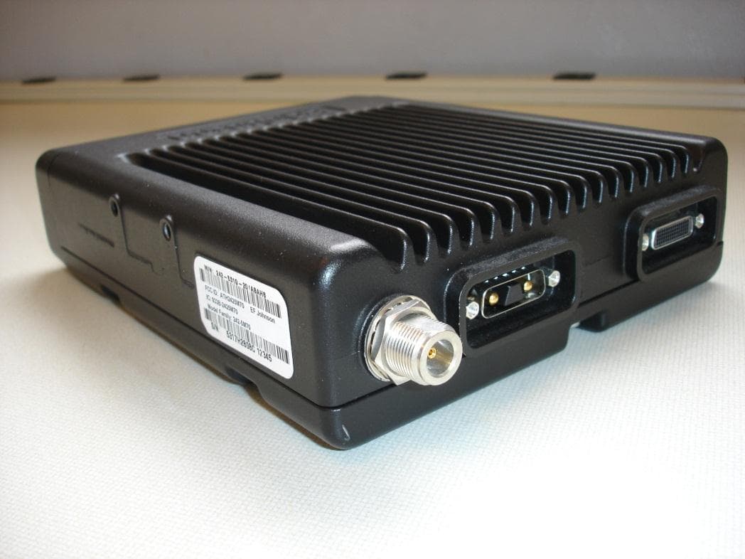
ATH2425M80
Nov 19, 2015DUAL BAND VHF AND 700/800 MHz MOBILE TRANSCEIVER
Equipment Class
TNB - Licensed Non-Broadcast Station Transmitter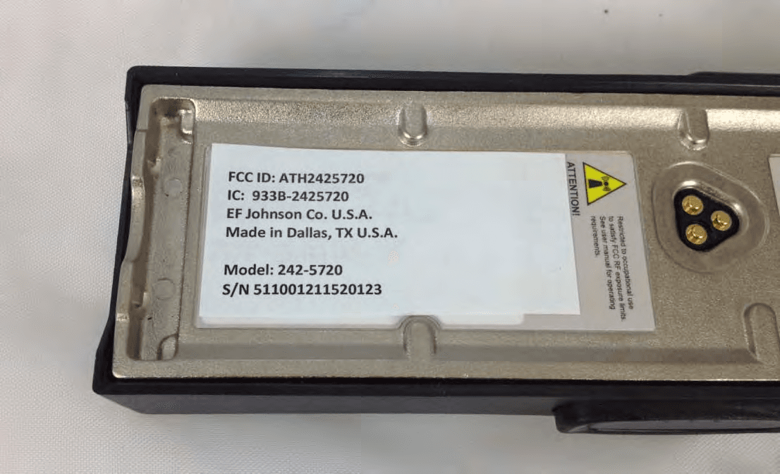
ATH2425720
Sep 30, 2012VP 600 UHF Land Mobile Radio Transceiver
Equipment Class
TNF - Licensed Non-Broadcast Transmitter Held to Face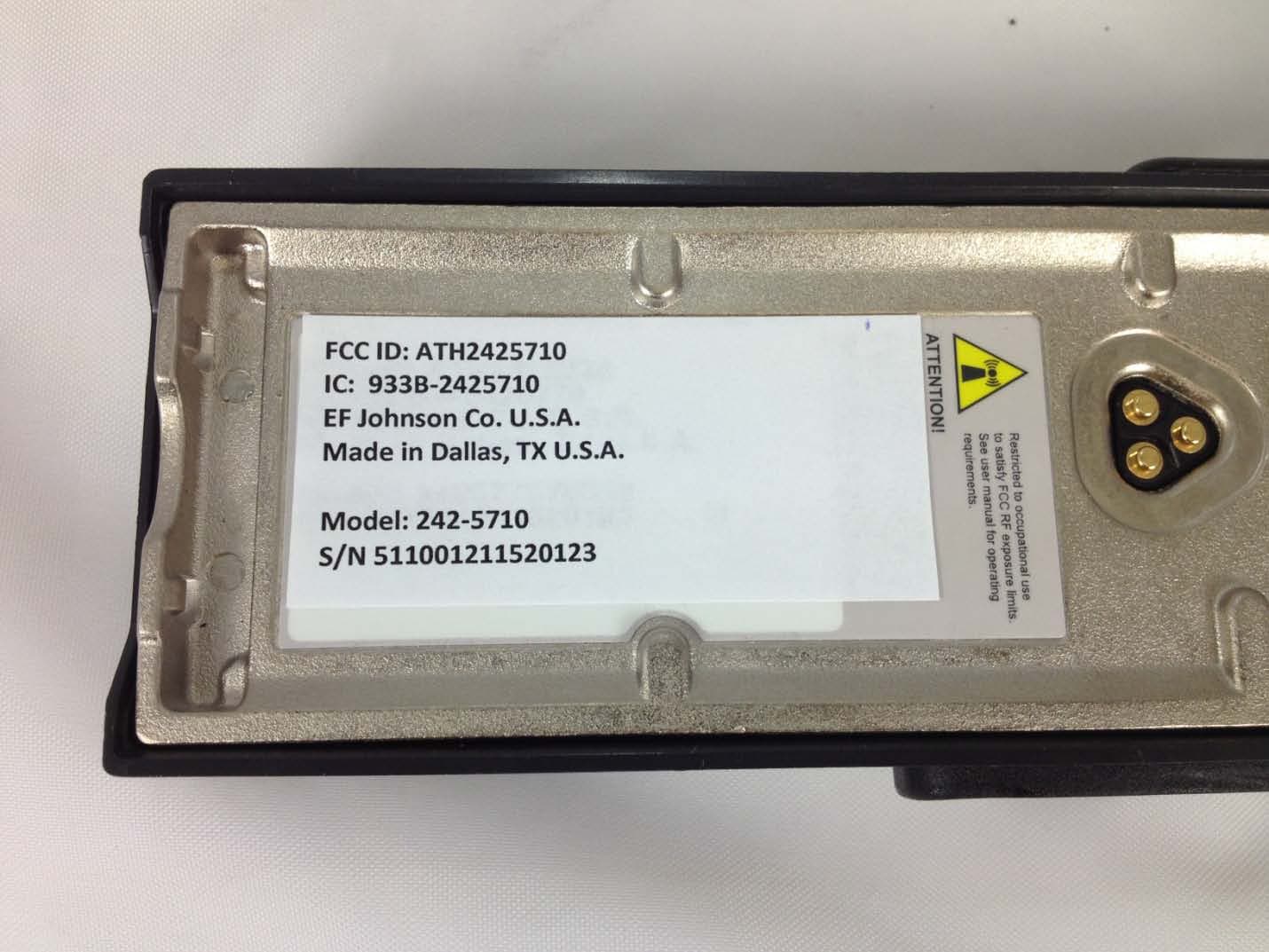
ATH2425710
Sep 16, 2012Portable VHF Push-To-Talk (PTT) Radio Transceiver
Equipment Class
TNF - Licensed Non-Broadcast Transmitter Held to Face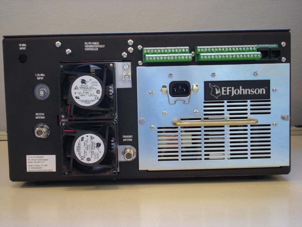
ATH2422607
Mar 07, 2010700 MHz LAND MOBILE REPEATER
Equipment Class
TNB - Licensed Non-Broadcast Station Transmitter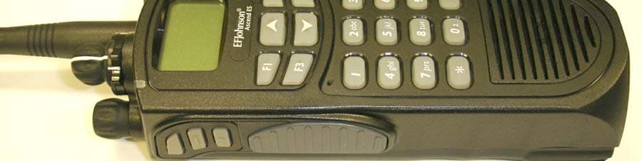
ATH2425112
Mar 17, 20085100 ES Series VHF Radio
Equipment Class
TNF - Licensed Non-Broadcast Transmitter Held to Face