ATH2425111Portable VHF 136-174 MHz
E F Johnson Company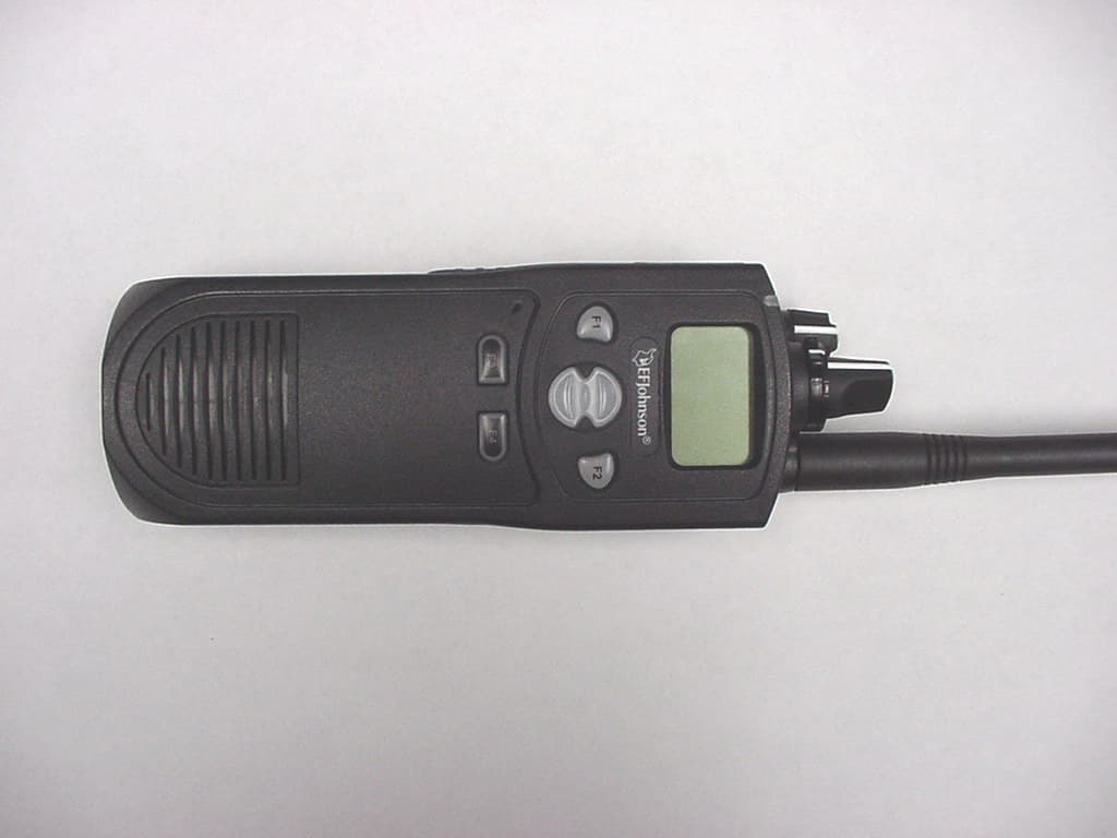
Click to zoom
Application Details
- Equipment Class
- TNF - Licensed Non-Broadcast Transmitter Held to Face
- Date of Grant
- Nov 20, 2004
- Application Purpose
- Original Equipment
- Date of Application
- Nov 20, 2004
- Equipment Note
- Portable VHF 136-174 MHz
- Frequency Range
- 136.00000000 - 174.00000000
- Company
- E F Johnson Company
- Country
- United States
Documents & Files
Document Text
Text extracted from the exhibit documents filed with the FCC. Open a document above to read the original.
Users Manual
Rhein Tech Laboratories Report #: 2004164 360 Herndon Parkway FCC ID: ATH2425111 Suite 1400 Model: 242-51xx Herndon, VA 20170 Standards: FCC Part 90 &IC RSS-119 http://www.rheintech.com Date: November 4, 2004 . Page 53 of 78 APPENDIX K: USER’S MANUAL Please refer to the Operator’s Manual. DIGITAL/ANALOG PORTABLE RADIO OPERATING MANUAL 5100 SERIES PORTABLERADIO VHF/UHF/700 and 800 MH Z PROJECT25 CONVENTIONAL SMARTNET ® /S MARTZONE ® 7.2 VDC, 1 and 5 Watts (VHF); 1 and 4 Watts (UHF); 1 and 3 Watts (700/800 MHz) Part No. 242-51xx-xxx 3 RF EXPOSURE INFORMATION RF ENERGY EXPOSURE AWARENESS AND CONTROL INFORMATION, AND OPERATIONAL INSTRUCTIONS FOR FCC OCCUPATIONAL USE REQUIREMENTS BEFORE USING YOUR PORTABLE 2-WAY RADIO, READ THIS IMPORTANT RF ENERGY AWARENESS AND CONTROL INFORMATION AND OPERATIONAL INSTRUCTIONS TO ENSURE COMPLIANCE WITH THE FCC’S RF EXPOSURE GUIDELINES. NOTICE: This radio is intended for use in occupa- tional/controlled conditions, where users have full knowledge of their exposure and can exercise control over their exposure to meet FCC limits. This radio device is NOT authorized for general population, consumer, or any other use. This 2-way radio uses electromagnetic energy in the radio frequency (RF) spectrum to provide commu- nications between two or more users over a distance. It uses radio frequency (RF) energy or radio waves to send and receive calls. RF energy is one form of elec- tromagnetic energy. Other forms include, but are not limited to, electric power, sunlight and x-rays. RF energy, however, should not be confused with these other forms of electromagnetic energy, which when used improperly can cause biological damage. Very high levels of x-rays, for example, can damage tissues and genetic material. Experts in science, engineering, medicine, health and industry work with organizations to develop stan- dards for exposure to RF energy. These standards provide recommended levels of RF exposure for both workers and the general public. These recommended RF exposure levels include substantial margins of protection. All 2-way radios marketed in North America are designed, manufactured and tested to ensure they meet government established RF expo- sure levels. In addition, manufacturers also recom- mend specific operating instructions to users of 2-way radios. These instructions are important because they inform users about RF energy exposure and provide simple procedures on how to control it. Please refer to the following websites for more information on what RF energy exposure is and how to control your expo- sure to assure compliance with established RF expo- sure limits. •http://www.fcc.gov/oet/rfsafety/rf-faqs.html •http://www.osha.gov/SLTC/ radiofrequencyradiation/index.html FEDERAL COMMUNICATIONS COMMISSION REGULATIONS The FCC rules require manufacturers to comply with the FCC RF energy exposure limits for portable 2-way radios before they can be marketed in the U.S. When 2-way radios are used as a consequence of employment, the FCC requires users to be fully aware of and able to control their exposure to meet occupa- tional requirements. Exposure awareness can be facili- tated by the use of a product label directing users to specific user awareness information. Your EFJohnson 2-way radio has a RF exposure product label. Also, your EFJohnson user manual, or product manual, or separate safety booklet includes information and oper- ating instructions required to control your RF exposure and to satisfy compliance requirements. COMPLIANCE WITH RF EXPOSURE STANDARDS Your EFJohnson 2-way radio is designed and tested to comply with a number of national and international standards and guidelines (listed below) for human exposure to radio frequency electromagnetic energy. This radio complies with the IEEE and ICNIRP expo- sure limits for occupational/controlled RF exposure environment at operating duty factors of up to 50% transmitting and is authorized by the FCC for occupa- tional use only. In terms of measuring RF energy for compliance with the FCC exposure guidelines, your radio radiates measurable RF energy only while it is transmitting (during talking), not when it is receiving (listening) or in standby mode. Note: The approved batteries supplied with this radio are rated for a 5-5-90 duty factor (5% talk-5% listen - 90% standby), even though this radio complies with the FCC occupational RF exposure limits and may operate at duty factors of up to 50% talk. 4 RF EXPOSURE INFORMATION Your EFJohnson 2-way radio complies with the following RF energy exposure standards and guide- lines: •United States Federal Communications Commis- sion, Code of Federal Regulations; 47 CFR §§ 1.1307, 1.1310, 2.1091 and 2.1093 •American National Standards Institute (ANSI) / Institute of Electrical and Electronic Engineers (IEEE) C95. 1-1992 •Institute of Electrical and Electronic Engineers (IEEE) C95.1-1999 Edition RF EXPOSURE COMPLIANCE AND CONTROL GUIDELINES AND OPERATING INSTRUCTIONS To control your exposure and ensure compliance with the occupational/controlled environment expo- sure limits always adhere to the following procedures. Guidelines : •Do not remove the RF Exposure Label from the device. •User awareness instructions should accompany device when transferred to other users. •Do not use this device if the operational require- ments described herein are not met. Operating Instructions : •Transmit no more than the rated duty factor of 50% of the time. To transmit (talk), push the Push-To- Talk (PTT) button. To receive calls, release the PTT button. Transmitting 50% of the time, or less, is important because this radio generates measurable RF energy exposure only when transmitting (in terms of measuring for standards compliance). •Hold the radio in a vertical position in front of face with the microphone (and the other parts of the radio, including the antenna) at least one inch (2.5 am) away from the nose. Keeping the radio at the proper distance is important because RF exposure…
Text truncated - open the document above for the full version.
Attestation Statements
Rhein Tech Laboratories Report #: 2004164 360 Herndon Parkway FCC ID: ATH2425111 Suite 1400 Model: 242-51xx Herndon, VA 20170 Standards: FCC Part 90 &IC RSS-119 http://www.rheintech.com Date: November 4, 2004 . Page 45 of 78 APPENDIX D: ATTESTATION LETTER Please see the following page. Waseca Office: E.F. Johnson Company • 299 Johnson Ave., P.O. Box 1249 • Waseca, MN 56093-0514 • 800-328-3911 • 507-835-6222 • Fax 507-835-8356 www.efjohnson.com September 14, 2004 Federal Communications Commission EQUIPMENT AUTHORIZATION BRANCH 7435 Oakland Mills Road Columbia, MD 21046 Re: Programming Capability Dear FCC Representative; Reference part 90.203(e), frequency programming capability. The end user will not be able to program the channel frequencies. A service shop or authorized agent using a special programming cable and computer software can program the allowed TX/RX frequencies. The end user can only select from the preprogrammed channels using the channel select knob. The software and programming cable are not available to the end user. Sincerely, John Oblak VP New Technology E.F. Johnson Co.
Cover Letter(s)
Rhein Tech Laboratories Report #: 2004164 360 Herndon Parkway FCC ID: ATH2425111 Suite 1400 Model: 242-51xx Herndon, VA 20170 Standards: FCC Part 90 &IC RSS-119 http://www.rheintech.com Date: November 4, 2004 . Page 44 of 78 APPENDIX C: CONFIDENTIALITY REQUEST LETTER Please see the following page. Waseca Office: E.F. Johnson Company • 299 Johnson Ave., P.O. Box 1249 • Waseca, MN 56093-0514 • 800-328-3911 • 507-835-6222 • Fax 507-835-8356 www.efjohnson.com September 14, 2004 Federal Communications Commission 7435 Oakland Mills Road Columbia, MD 21046 To Whom It May Concern: The following information is to be held confidential pursuant of 47 CFR Part 0 §0.457 and Section 552(b)(4) of the Freedom of Information Act, because the information provided contains trade secrets and proprietary. If made public, the information might be used to the disadvantage of the applicant in the market place. • Schematics • Product Description • Block Diagram • Bill of Materials (Parts List) Sincerely, John Oblak VP New Technology E. F. Johnson Co.
Cover Letter(s)
Rhein Tech Laboratories Report #: 2004164 360 Herndon Parkway FCC ID: ATH2425111 Suite 1400 Model: 242-51xx Herndon, VA 20170 Standards: FCC Part 90 &IC RSS-119 http://www.rheintech.com Date: November 4, 2004 . Page 43 of 78 APPENDIX B: AGENCY AUTHORIZATION LETTER Please see the following page. Waseca Office: E.F. Johnson Company • 299 Johnson Ave., P.O. Box 1249 • Waseca, MN 56093-0514 • 800-328-3911 • 507-835-6222 • Fax 507-835-8356 www.efjohnson.com September 14, 2004 Federal Communications Commission EQUIPMENT AUTHORIZATION BRANCH 7435 Oakland Mills Road Columbia, MD 21046 Re: Agent Authorization To Whom It May Concern: E. F. Johnson Co. hereby authorizes Rhein Tech Laboratories, Inc. (RTL), 360 Herndon Parkway, Suite 1400, Herndon, VA 20170 to act as agent. APPLICANT ANTI-DRUG ABUSE CERTIFICATION: In signing this letter, Applicant certifies that, in the case of an individual applicant, he or she is not subject to a denial of federal benefits, that includes: FCC benefits, pursuant to Section 5301 of the Anti-Drug Abuse Act of 1988, 21 U.S.C. 853(a), or, in the case of a non-individual applicant. No party to the application is subject to a denial of federal benefits, that includes FCC benefits, pursuant to that section. For the definition of a “party” for these purposes, see 47 CFR 1.2002(b). Sincerely, John Oblak VP New Technology E.F. Johnson Co.
Cover Letter(s)
American Telecommunications Certification Body Inc. 6731 Whittier Ave, McLean, VA 22101 November 16, 2004 RE: FCC ID: ATH2425111_ATCB001894 Attention: Kathy Grzovic I have a few comments on this Application. Please note that further comments may arise in response to answers provided to the questions below. 1. FYI - Please note that radiated spurious ERP measurements should be compared to ERP power measurements not conducted power measurements. While the end result of both is -20dBm, the correct units and correct methods should be used. 2. Please note that while it may be correct to use the conducted antenna terminal power for the purpose of listing on the grant, you will still need to provide EIRP power measurements to justify not performing SAR on the device. Please also note that the power level required to be met for the exclusions list would be 174MHz, not 150MHz. The exclusions list for power at 174MHz (upper end of this device operation) for devices used greater than 2.5cm is 900/.174 or 5.2W. While you state that the worse case EIRP at 150MHz is 4.4W this may not be the worse case condition. As the conducted power at 174MHz is 6.3Watts and as the gain of the antenna is not specified it is possible that the EIRP value at 174MHz would be in excess of the 5.2Watts exclusions list power limit. Even a straight extrapolation from the 4.4W 150MHz measured value, assuming that antenna gain may outweigh the 50% PTT averaging at 174MHz, indicates that the device may not pass the 5.2 watts at 174MHz. Please measure the EIRP at 174MHz and justify that the 174MHz EIRP 50% PTT power is below 5.2W. Otherwise, SAR may be required for this device and it may have to be sent to the FCC for certification. 3. FYI - Please note that while the conducted antenna terminal power is appropriate to list on the grant, the ERP of the device should also be listed in the grant notes. Please consider providing maximum ERP power values for this device. 4. Dennis Ward mailto:[email protected] The items indicated above must be submitted before processing can continue on the above referenced application. Failure to provide the requested information may result in application termination. Correspondence should be considered part of the permanent submission and may be viewed from the Internet after a Grant of Equipment Authorization is issued. Please do not respond to this correspondence using the email reply button. In order for your response to be processed expeditiously, you must submit your documents through the AmericanTCB.com website. Also, please note that partial responses increase processing time and should not be submitted. Any questions about the content of this correspondence should be directed to the sender.
Cover Letter(s)
American Telecommunications Certification Body Inc. 6731 Whittier Ave, McLean, VA 22101 November 16, 2004 RE: FCC ID: ATH2425111_ATCB001894 Attention: Kathy Grzovic I have a few comments on this Application. Please note that further comments may arise in response to answers provided to the questions below. 1. FYI - Please note that radiated spurious ERP measurements should be compared to ERP power measurements not conducted power measurements. While the end result of both is - 20dBm, the correct units and correct methods should be used. Response : Thank you. 2. Please note that while it may be correct to use the conducted antenna terminal power for the purpose of listing on the grant, you will still need to provide EIRP power measurements to justify not performing SAR on the device. Please also note that the power level required to be met for the exclusions list would be 174MHz, not 150MHz. The exclusions list for power at 174MHz (upper end of this device operation) for devices used greater than 2.5cm is 900/.174 or 5.2W. While you state that the worse case EIRP at 150MHz is 4.4W this may not be the worse case condition. As the conducted power at 174MHz is 6.3Watts and as the gain of the antenna is not specified it is possible that the EIRP value at 174MHz would be in excess of the 5.2Watts exclusions list power limit. Even a straight extrapolation from the 4.4W 150MHz measured value, assuming that antenna gain may outweigh the 50% PTT averaging at 174MHz, indicates that the device may not pass the 5.2 watts at 174MHz. Please measure the EIRP at 174MHz and justify that the 174MHz EIRP 50% PTT power is below 5.2W. Otherwise, SAR may be required for this device and it may have to be sent to the FCC for certification. Response : Please refer to the revised RF Exposure exhibit uploaded with this response. 3. FYI - Please note that while the conducted antenna terminal power is appropriate to list on the grant, the ERP of the device should also be listed in the grant notes. Please consider providing maximum ERP power values for this device. Response : Thank you. 4. Dennis Ward mailto:[email protected] The items indicated above must be submitted before processing can continue on the above referenced application. Failure to provide the requested information may result in application termination. Correspondence should be considered part of the permanent submission and may be viewed from the Internet after a Grant of Equipment Authorization is issued. Please do not respond to this correspondence using the email reply button. In order for your response to be processed expeditiously, you must submit your documents through the AmericanTCB.com website. Also, please note that partial responses increase processing time and should not be submitted. Any questions about the content of this correspondence should be directed to the sender.
External Photos
Rhein Tech Laboratories Report #: 2004164 360 Herndon Parkway FCC ID: ATH2425111 Suite 1400 Model: 242-51xx Herndon, VA 20170 Standards: FCC Part 90 &IC RSS-119 http://www.rheintech.com Date: November 4, 2004 . Page 58 of 78 APPENDIX M: EXTERNAL PHOTOGRAPHS PHOTOGRAPH 7: RADIO FRONT Rhein Tech Laboratories Report #: 2004164 360 Herndon Parkway FCC ID: ATH2425111 Suite 1400 Model: 242-51xx Herndon, VA 20170 Standards: FCC Part 90 &IC RSS-119 http://www.rheintech.com Date: November 4, 2004 . Page 59 of 78 PHOTOGRAPH 8: RADIO BACK Rhein Tech Laboratories Report #: 2004164 360 Herndon Parkway FCC ID: ATH2425111 Suite 1400 Model: 242-51xx Herndon, VA 20170 Standards: FCC Part 90 &IC RSS-119 http://www.rheintech.com Date: November 4, 2004 . Page 60 of 78 PHOTOGRAPH 9: RADIO ACCESSORY CONNECTOR SIDE Rhein Tech Laboratories Report #: 2004164 360 Herndon Parkway FCC ID: ATH2425111 Suite 1400 Model: 242-51xx Herndon, VA 20170 Standards: FCC Part 90 &IC RSS-119 http://www.rheintech.com Date: November 4, 2004 . Page 61 of 78 PHOTOGRAPH 10: RADIO TOP Rhein Tech Laboratories Report #: 2004164 360 Herndon Parkway FCC ID: ATH2425111 Suite 1400 Model: 242-51xx Herndon, VA 20170 Standards: FCC Part 90 &IC RSS-119 http://www.rheintech.com Date: November 4, 2004 . Page 62 of 78 PHOTOGRAPH 11: RADIO PTT SIDE
ID Label/Location Info
Rhein Tech Laboratories Report #: 2004164 360 Herndon Parkway FCC ID: ATH2425111 Suite 1400 Model: 242-51xx Herndon, VA 20170 Standards: FCC Part 90 &IC RSS-119 http://www.rheintech.com Date: November 4, 2004 . Page 46 of 78 APPENDIX E: LABEL AND LABEL LOCATION PHOTOGRAPH 1: FCC ID / IC ID LABEL AND LOCATION Rhein Tech Laboratories Report #: 2004164 360 Herndon Parkway FCC ID: ATH2425111 Suite 1400 Model: 242-51xx Herndon, VA 20170 Standards: FCC Part 90 &IC RSS-119 http://www.rheintech.com Date: November 4, 2004 . Page 47 of 78 PHOTOGRAPH 2: RF WARNING LABEL
Internal Photos
Rhein Tech Laboratories Report #: 2004164 360 Herndon Parkway FCC ID: ATH2425111 Suite 1400 Model: 242-51xx Herndon, VA 20170 Standards: FCC Part 90 &IC RSS-119 http://www.rheintech.com Date: November 4, 2004 . Page 63 of 78 APPENDIX N: INTERNAL PHOTOGRAPHS PHOTOGRAPH 12: BATTERY REMOVED FROM RADIO Rhein Tech Laboratories Report #: 2004164 360 Herndon Parkway FCC ID: ATH2425111 Suite 1400 Model: 242-51xx Herndon, VA 20170 Standards: FCC Part 90 &IC RSS-119 http://www.rheintech.com Date: November 4, 2004 . Page 64 of 78 PHOTOGRAPH 13: CHASSIS WITH SHIELDS Rhein Tech Laboratories Report #: 2004164 360 Herndon Parkway FCC ID: ATH2425111 Suite 1400 Model: 242-51xx Herndon, VA 20170 Standards: FCC Part 90 &IC RSS-119 http://www.rheintech.com Date: November 4, 2004 . Page 65 of 78 PHOTOGRAPH 14: CHASSIS WITH SHIELDS REMOVED Rhein Tech Laboratories Report #: 2004164 360 Herndon Parkway FCC ID: ATH2425111 Suite 1400 Model: 242-51xx Herndon, VA 20170 Standards: FCC Part 90 &IC RSS-119 http://www.rheintech.com Date: November 4, 2004 . Page 66 of 78 PHOTOGRAPH 15: RF AND LOGIC BOARD BACK OUT OF CHASSIS Rhein Tech Laboratories Report #: 2004164 360 Herndon Parkway FCC ID: ATH2425111 Suite 1400 Model: 242-51xx Herndon, VA 20170 Standards: FCC Part 90 &IC RSS-119 http://www.rheintech.com Date: November 4, 2004 . Page 67 of 78 PHOTOGRAPH 16: LOGIC BOARD BOTTOM Rhein Tech Laboratories Report #: 2004164 360 Herndon Parkway FCC ID: ATH2425111 Suite 1400 Model: 242-51xx Herndon, VA 20170 Standards: FCC Part 90 &IC RSS-119 http://www.rheintech.com Date: November 4, 2004 . Page 68 of 78 PHOTOGRAPH 17: LOGIC BOARD TOP Rhein Tech Laboratories Report #: 2004164 360 Herndon Parkway FCC ID: ATH2425111 Suite 1400 Model: 242-51xx Herndon, VA 20170 Standards: FCC Part 90 &IC RSS-119 http://www.rheintech.com Date: November 4, 2004 . Page 69 of 78 PHOTOGRAPH 18: RF BOARD BOTTOM Rhein Tech Laboratories Report #: 2004164 360 Herndon Parkway FCC ID: ATH2425111 Suite 1400 Model: 242-51xx Herndon, VA 20170 Standards: FCC Part 90 &IC RSS-119 http://www.rheintech.com Date: November 4, 2004 . Page 70 of 78 PHOTOGRAPH 19: RF BOARD TOP Rhein Tech Laboratories Report #: 2004164 360 Herndon Parkway FCC ID: ATH2425111 Suite 1400 Model: 242-51xx Herndon, VA 20170 Standards: FCC Part 90 &IC RSS-119 http://www.rheintech.com Date: November 4, 2004 . Page 71 of 78 PHOTOGRAPH 20: USER INTERFACE BOARD IN FRONT COVER Rhein Tech Laboratories Report #: 2004164 360 Herndon Parkway FCC ID: ATH2425111 Suite 1400 Model: 242-51xx Herndon, VA 20170 Standards: FCC Part 90 &IC RSS-119 http://www.rheintech.com Date: November 4, 2004 . Page 72 of 78 PHOTOGRAPH 21: USER INTERFACE BOARD BACK Rhein Tech Laboratories Report #: 2004164 360 Herndon Parkway FCC ID: ATH2425111 Suite 1400 Model: 242-51xx Herndon, VA 20170 Standards: FCC Part 90 &IC RSS-119 http://www.rheintech.com Date: November 4, 2004 . Page 73 of 78 PHOTOGRAPH 22: USER INTERFACE BOARD FRONT
RF Exposure Info
Rhein Tech Laboratories Report #: 2004164 360 Herndon Parkway FCC ID: ATH2425111 Suite 1400 Model: 242-51xx Herndon, VA 20170 Standards: FCC Part 90 &IC RSS-119 http://www.rheintech.com Date: November 4, 2004 . Page 42 of 78 APPENDIX A: RF EXPOSURE FCC Rules and Regulations Part 1.1307, 1.1310, 2.1091, 2.1093: THIS DEVICE IS CATEGORICALLY EXCLUDED FROM RF EXPOSURE EVALUATION PER THE TCB EXCLUSION LIST DATED 17 JULY 2002. The worst case EIRP was 4.4 W at 150 MHz. Plugging this value into the occupation low threshold equation from the bottom of the TCB exclusion list gives the following: 900/f(GHz) = 900 / 0.150 = 6,000 mW = 6 W. Additionally, the EIRP was 1.4 W at 174 MHz. Plugging this value into the occupation low threshold equation from the bottom of the TCB exclusion list gives the following: 900/f(GHz) = 900 / 0.174 = 5,172 mW = 5.2 W. The power from this radio is below the low threshold. Additionally, this is a PTT radio with a maximum duty cycle of 50%, which would make the margin even greater between the power seen in actual use and the low threshold.
Test Report
Engineering and Testing for EMC and Safety Compliance 360 Herndon Parkway Suite 1400 Herndon, VA 20170 Phone: 703-689-0368; Fax: 703-689-2056; Metro: 703-471-6441 CERTIFICATION APPLICATION REPORT FCC PART 90 & INDUSTRY CANADA RSS-119 Test Lab: Rhein Tech Laboratories, Inc. Phone: 703-689-0368 360 Herndon Parkway Fax: 703-689-2056 Suite 1400 Web Site: www.rheintech.com Herndon, VA 20170 Contact: [email protected] Applicant: E.F. Johnson Company Phone: 507-835-6276 299 Johnson Ave. Fax: 507-835-6666 P.O. Box 1249 Email: [email protected] Waseca, MN 56093-0514 Contact: John Oblak FCC ID: ATH2425111 FRN NUMBER: 0005-8136-88 MODEL: 242-51xx RTL WORK ORDER NUMBER: 2004164 EQUIPMENT TYPE: PTT VHF RTL QUOTE NUMBER: QRTL04-309 DATE OF TEST REPORT: November 4, 2004 FCC Classification: TNF – Licensed Non-Broadcast Transmitter Held to Face FCC Rule Part(s): Part 90: Private Land Mobile Radio Services Industry Canada Standard: RSS-119: Land Mobile and Fixed Radio Transmitters and Receivers, 27.41MHz to 960MHz Frequency Range (MHz) Output Power (W) Frequency Tolerance (ppm) Emission Designator 136 to 174 6.1 0.5 11K0F3E 136 to 174 6.1 0.5 16K0F3E 136 to 174 6.1 0.5 8K00F1E 136 to 174 6.1 0.5 8K00F1D We, the undersigned, hereby declare that the equipment tested and referenced in this report conforms to the identified standard(s) as described in this test report. No modifications were made to the equipment during testing in order to achieve compliance with these standards. Furthermore, there was no deviation from, additions to or exclusions from the FCC Part 2, FCC Part 90, Industry Canada RSS-119, ANSI C63.2, ANSI/TIA/EIA603 and ANSI/TIA/EIA 603-1. Signature: Date: November 4, 2004 Typed/Printed Name: Desmond A. Fraser Position: President Signature: Date: November 4, 2004 Typed/Printed Name: Daniel Baltzell Position: Test Engineer Rhein Tech Laboratories Report #: 2004164 360 Herndon Parkway FCC ID: ATH2425111 Suite 1400 Model: 242-51xx Herndon, VA 20170 Standards: FCC Part 90 &IC RSS-119 http://www.rheintech.com Date: November 4, 2004 . Page 2 of 78 TABLE OF CONTENTS 1 GENERAL INFORMATION ...................................................................................................................................6 1.1 SCOPE .........................................................................................................................................................6 1.2 TEST FACILITY............................................................................................................................................6 1.3 RELATED SUBMITTAL(S)/GRANT(S) .........................................................................................................6 2 EQUIPMENT INFORMATION................................................................................................................................7 2.1 TEST SYSTEM DETAILS.............................................................................................................................7 2.2 WORST CASE CONFIGURATION OF TESTED SYSTEM..........................................................................8 3 FCC PART 2.1033(C)(8); DC VOLTAGES AND CURRENTS ..............................................................................9 4 RF POWER OUTPUT - §2.1046, RSS-119 §6.2....................................................................................................9 4.1 ANSI/TIA/EIA-603-2002, SECTION 2.2.1 TEST PROCEDURE ...................................................................9 4.2 RF POWER OUTPUT TEST EQUIPMENT ..................................................................................................9 4.3 RF POWER OUTPUT TEST DATA ............................................................................................................10 5 MODULATION CHARACTERISTICS - §2.1047 TEST PROCEDURE, RSS-119 §6.6 .......................................11 5.1 MODULATION CHARACTERISTICS TEST EQUIPMENT.........................................................................11 6 FCC PART 2 §2.1047 (A): MODULATION CHARACTERISTICS - AUDIO FREQUENCY RESPONSE............12 6.1 TEST PROCEDURE...................................................................................................................................12 6.2 TEST DATA ................................................................................................................................................12 7 FCC PART 2 §2.1047 (A): MODULATION CHARACTERISTICS - AUDIO LOW PASS FILTER RESPONSE 13 7.1 TEST PROCEDURE...................................................................................................................................13 7.2 TEST DATA ................................................................................................................................................13 8 FCC PART 2 §2.1047 (B): MODULATION CHARACTERISTICS - MODULATION LIMITING .........................14 8.1 TEST PROCEDURE...................................................................................................................................14 8.2 TEST DATA ................................................................................................................................................14 9 OCCUPIED BANDWIDTH - §2.1049, RSS-119 §6.4...........................................................................................18 9.1 OCCUPIED BANDWIDTH - §2.1049 TEST PROCEDURE ........................................................................18 9.2 OCCUPIED BANDWIDTH TEST EQUIPMENT..........................................................................................18 9.3 OCCUPIED BANDWIDTH TEST DATA .....................................................................................................19 10 SPURIOUS EMISSIONS AT ANTENNA TERMINAL - §2.1051, RSS-119 §6.3 ............................................22 10.1 SPURIOUS EMISSIONS AT ANTENNA TERMINAL - §2.1051 TEST PROCEDURE ..................…
Text truncated - open the document above for the full version.
Contact Information
Applicant
Karthik Rangarajan(SR VP Engineering)
Technical Contact
Rhein Tech LaboratoriesDesmond A Fraser
[email protected]703-689-0368
360 Herndon Parkway, Suite 1400 · Herndon, Virginia · United States
Technical Specifications
| # | Rule Parts | Frequency Range | Power Output | Emission | Tolerance |
|---|---|---|---|---|---|
| 4 | 9 | 136 MHz - 174 MHz | 6.1 W | 8K00F1D | 0.5 ppm |
Other Applications from E F Johnson Company
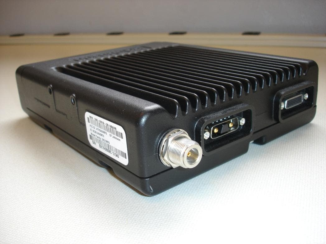
ATH2425M80
Nov 19, 2015DUAL BAND VHF AND 700/800 MHz MOBILE TRANSCEIVER
Equipment Class
TNB - Licensed Non-Broadcast Station Transmitter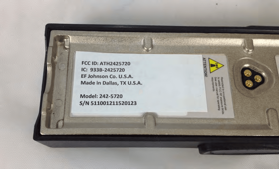
ATH2425720
Sep 30, 2012VP 600 UHF Land Mobile Radio Transceiver
Equipment Class
TNF - Licensed Non-Broadcast Transmitter Held to Face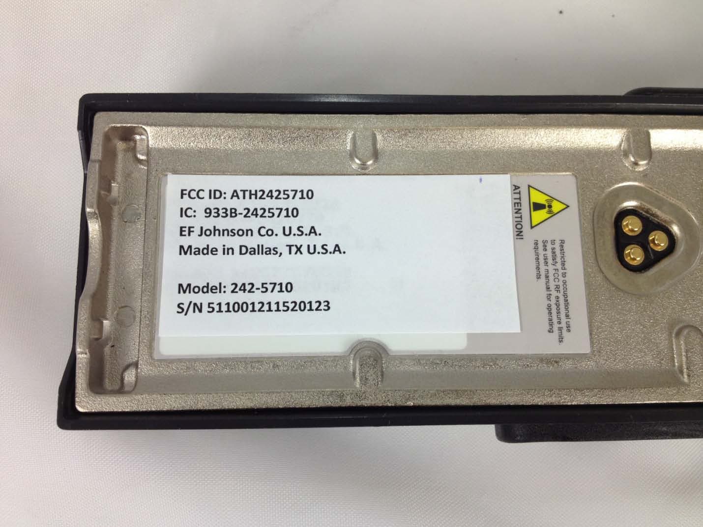
ATH2425710
Sep 16, 2012Portable VHF Push-To-Talk (PTT) Radio Transceiver
Equipment Class
TNF - Licensed Non-Broadcast Transmitter Held to Face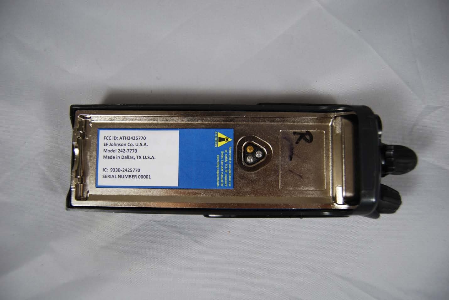
ATH2425770
Feb 09, 2012Vantage 700/800 MHz Portable Radio
Equipment Class
TNF - Licensed Non-Broadcast Transmitter Held to Face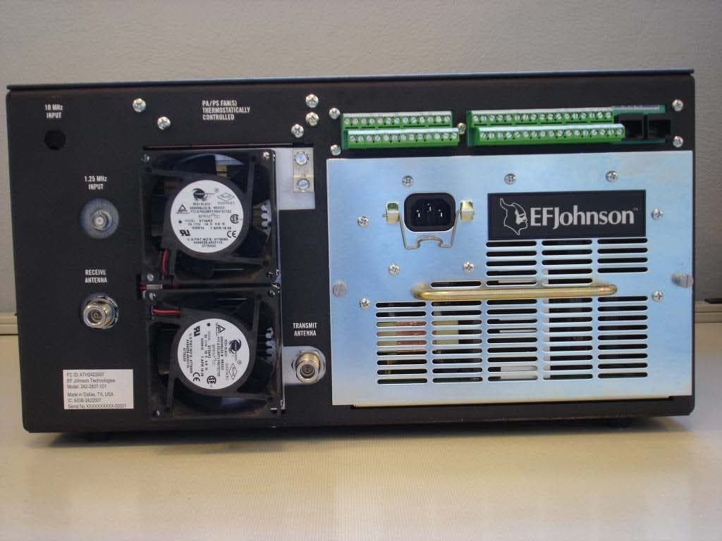
ATH2422607
Mar 07, 2010700 MHz LAND MOBILE REPEATER
Equipment Class
TNB - Licensed Non-Broadcast Station Transmitter