ATH2425180PTT 800 MHz SMR
E F Johnson Company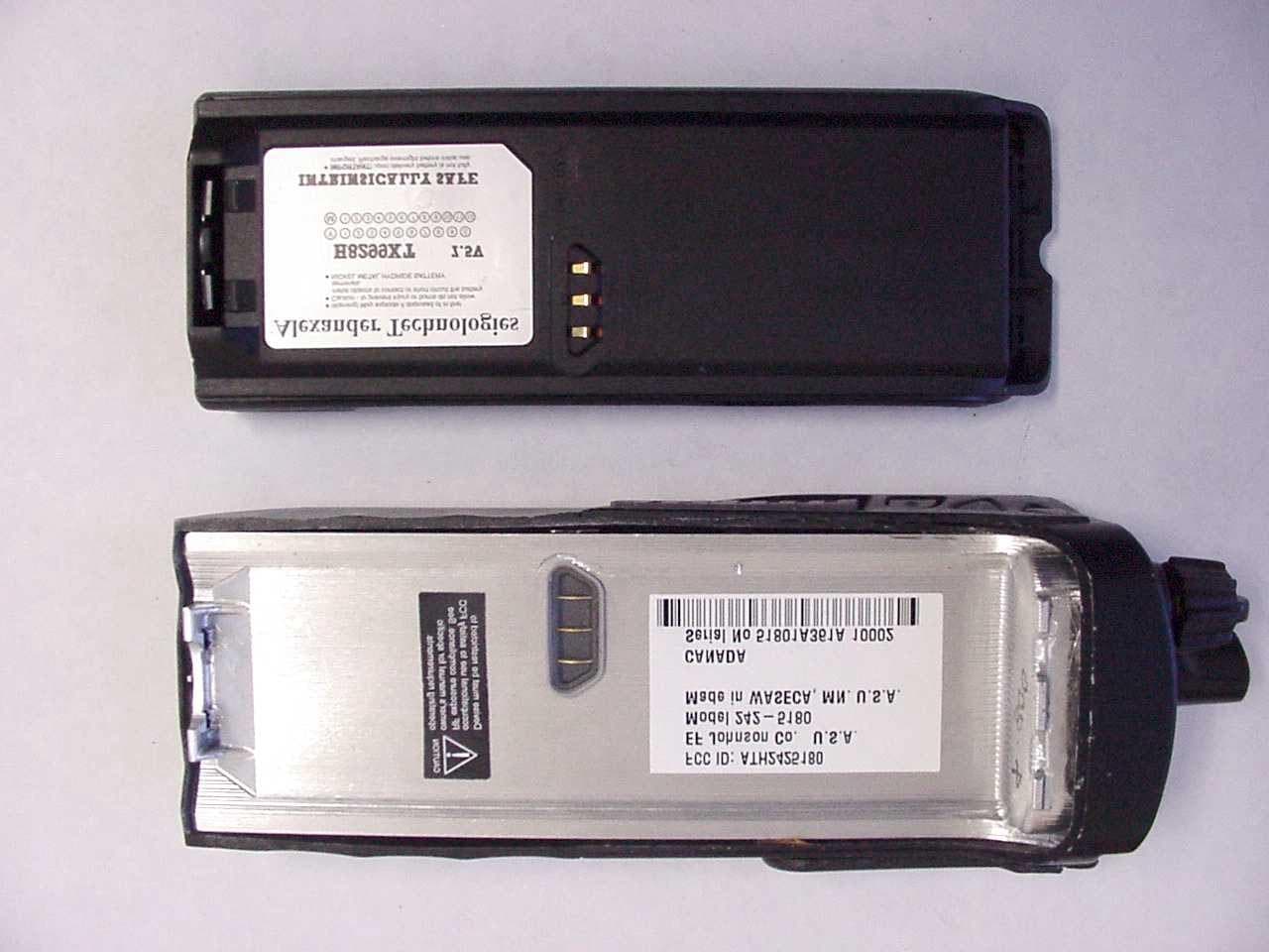
Click to zoom
Application Details
- Equipment Class
- TNF - Licensed Non-Broadcast Transmitter Held to Face
- Date of Grant
- May 08, 2002
- Application Purpose
- Original Equipment
- Date of Application
- Feb 26, 2002
- Equipment Note
- PTT 800 MHz SMR
- Frequency Range
- 806.01250000 - 868.98750000
- Company
- E F Johnson Company
- Country
- United States
Documents & Files
Document Text
Text extracted from the exhibit documents filed with the FCC. Open a document above to read the original.
Users Manual
1 51xx Series FM Portable Radio Project 25, Conventional SMARTNET ™ , SmartZone ® PRELIMINARY OPERATING MANUAL LAND MOBILE PRODUCT WARRANTY - The manufacturer’s warranty statement for this product is available from your product supplier or from the E.F. Johnson Company, 299 Johnson Avenue, Box 1249, Waseca, MN 56093-0514. Phone (507) 835-6222. Copyright© 2001 by the E.F. Johnson Company E.F. Johnson Company, which was founded in 1923, designs, manufac- tures, and markets radio communication products, systems, and services worldwide. E.F. Johnson produces equipment for land mobile radio and mobiletelephone services which include business, industrial, government, public safety, and personal users. Viking Head/EFJohnson logo and Call Guard® are trademarks of the E.F. Johnson Company. SMARTNET™, SmartZone®, Call Alert™, Enhanced Private Conversation™, and Private Conversation II™ are trademarks of Motorola, Inc. All other company and/or product names used in this manual are trademarks and/or registered trademarks of their respective manufacturer. The IMBE™ voice coding technology embodied in this product is protected by intellectual property rights including patent rights of Digital Voice Systems, Inc. SAFETY TRAINING INFORMATION 4 SAFETY TRAINING INFORMATION WARNING This radio produces RF electromagnetic energy when transmitting and is designed and classified for “Occupational Use Only”. Radio equipment with this classification must be used only during the course of employ- ment by individuals aware of the hazards and the ways to minimize such hazards. This radio is NOT intended for use by the General Population in an uncontrolled environment. This radio has been tested and complies with FCC RF exposure limits for “Occupational Use Only”. In addition, it complies with the following standards and guidelines with regard to RF energy and electromagnetic energy levels and evaluation of such levels for exposure to humans: •FCC OET Bulletin 65 Edition 97-01 Supplement C, Evaluating Compliance with FCC Guidelines for Human Exposure to Radio Frequency Electromagnetic Fields. •American National Standards Institute (C95.1-1992), IEEE Standard for Safety Levels with Respect to Human Exposure to Radio Frequency Electromagnetic Fields, 3 kHz to 300 GHz. •American National Standards Institute (C95.3 -1992), IEEE Recom- mended Practice for the Measurement of Potentially Hazardous Electromagnetic Fields - RF and Microwave. CAUTION To ensure that your exposure to RF electromagnetic energy is within the FCC allowable limits for occupational use, always adhere to the following guidelines: •DO NOT operate the radio without the proper antenna attached. This may damage the radio and cause FCC RF exposure limits to be exceeded. The proper antenna is the antenna supplied with the radio by the manufacturer or an antenna specifically authorized by the manufacturer for use with this radio. SAFETY TRAINING INFORMATION 5 •DO NOT transmit more than 50% of total radio use time (50% duty cycle). Transmitting for more than 50% of the time can cause FCC RF exposure compliance requirements to be exceeded. This radio is transmitting when- ever Tx is indicated in the display. Pressing the PTT switch on the side usually causes the radio to transmit. •DO NOT use any accessories not specifically authorized by the E.F. Johnson Company for use with this radio such as batteries, speaker- microphones, belt clips, and antennas. The use of unauthorized accessories can cause FCC RF exposure compliance requirements to be exceeded. •ALWAYS keep the antenna and radio at least 2.54 cm (1.0 inch) away from your body when transmitting to ensure FCC RF exposure compliance requirements are not exceeded. The best transmission quality results when the antenna is at least 5 cm (2 inches) away from your mouth and angled slightly to one side. NOTE: The preceding information is provided to make you aware of RF exposure and what to do to ensure that this radio is operated within FCC RF exposure limits. Electromagnetic Interference/Usage Compatibility This device complies with Part 15 of the FCC rules. Operation is subject to the condition that this device does not cause harmful interference. In addition, changes or modification to this equipment no expressly approved by the E.F. Johnson Company could void the user’s authority to operate this equipment (FCC Rules, 47CFR Part 15.19). DO NOT operate it in areas that are sensitive to RF energy such as aircraft, hospitals, blasting sites, and fuel storage sites. Areas with potentially flammable atmospheres are usually, but not always, clearly posted. These may include gas stations, fuel and chemical storage and transfer stations, below deck on boats, and areas where the air contains flammable chemicals or particles such as grain dust or metal powders. Dispose of the nickel metal-hydride battery used by this radio in accordance with local regulations. DO NOT dispose of it in fire because it can explode. Also, do not short the terminals because it may become very hot. FEATURES 6 FEATURES General Features •Programmable for the following modes of operation: – Conventional analog – Conventional Project 25 (digital) – SMARTNET™/SmartZone® trunked (analog or digital) •Up to 16 zones with up to 16 channels each programmable (256 channels total) •Large liquid crystal display (LCD) with backlight •Nine programmable option switches (full keypad model) •Standard and radio-wide scan modes •Time-out timer •Power-up password access available to prevent unauthorized usage Conventional Features •Up to 256 channels or talk groups programmable •Repeater talk-around •Monitor mode selected by option switch •Carrier or Call Guard ® controlled squelch on analog channels •Penalty and conversation timers •Priority channel sampling when scanning •Busy channel lockout (transmit disable on busy) •SecureNet ™ or 460 secure communication available on analog channels, DES-OFB on Project 25 channels •Individual ID calls on Project 25 cha…
Text truncated - open the document above for the full version.
Users Manual
Service Manualual 5100 SERIES PORTABLE DIGITAL/ANALOG VHF/UHF/800 MHz 7.2 VDC 5 & 1 W (VHF), 4 & 1 W (UHF), 3 W (800 MHz) Part No. 242-51xx-xxx First Printing September 2001 PRELIMINARY 51xx SERIES PORTABLE VHF/UHF/800 MHz PROJECT 25 (DIGITAL) AND ANALOG 7.5 VDC 5 & 1 W (VHF), 4 & 1 W (UHF), 3 W (800 MHz) Part No. 242-51xx-xxx Copyright© 2001 by the E.F. Johnson Company The E.F. Johnson Company, which was founded in 1923, provides wireless communication systems solutions for public safety, government, and commercial customers. The company designs, manufactures, and markets conventional and trunked radio systems, mobile and portable subscriber radios, repeaters, and Project 25 digital radio products. E.F. Johnson is a wholly owned subsidiary of Transcrypt International, Inc. Viking Head/EFJohnson logo, Call Guard ® , PCTrunk ™ , and PCTune ™ are registered trade- marks of the E.F. Johnson Company. SMARTNET ™ , SmartZone ® , SecureNet ™ , Call Alert ™ , Enhanced Private Conversation ™ , and Private Conversation II ™ are trademarks of Motorola, Inc. All other company and/or product names used in this manual are trademarks and/or reg- istered trademarks of their respective manufacturer. The IMBE™ voice coding technology embodied in this product is protected by intellectual property rights including patent rights of Digital Voice Systems, Inc. Information in this manual is subject to change without notice. TABLE OF CONTENTS ii September 2001 Part No. 001-5100-001 TABLE OF CONTENTS 1GENERAL INFORMATION 1.1SCOPE OF MANUAL. . . . . . . . . . . . . . . . . . . .1-1 1.2TRANSCEIVER DESCRIPTION. . . . . . . . . . .1-1 General . . . . . . . . . . . . . . . . . . . . . . . . . . . . . . . . 1-1 Analog/Digital Operation. . . . . . . . . . . . . . . . . . 1-1 Operating Protocols . . . . . . . . . . . . . . . . . . . . . . 1-1 18-Key/6-Key Models . . . . . . . . . . . . . . . . . . . . 1-1 Systems, Channels, and Zones . . . . . . . . . . . . . . 1-1 Secure Communication . . . . . . . . . . . . . . . . . . . 1-2 Programming . . . . . . . . . . . . . . . . . . . . . . . . . . . 1-2 Alignment. . . . . . . . . . . . . . . . . . . . . . . . . . . . . . 1-2 1.3PRODUCT WARRANTY . . . . . . . . . . . . . . . . .1-2 1.4PART NUMBER BREAKDOWN. . . . . . . . . . .1-3 1.5TRANSCEIVER IDENTIFICATION . . . . . . . .1-3 1.6ACCESSORIES. . . . . . . . . . . . . . . . . . . . . . . . .1-3 1.7FACTORY CUSTOMER SERVICE . . . . . . . .1-4 1.8FACTORY RETURNS . . . . . . . . . . . . . . . . . . .1-5 1.9REPLACEMENT PARTS. . . . . . . . . . . . . . . . .1-5 1.10 INTERNET HOME PAGE. . . . . . . . . . . . . . . . .1-5 2OPERATION 2.1FEATURES. . . . . . . . . . . . . . . . . . . . . . . . . . . . .2-1 General Featu res . . . . . . . . . . . . . . . . . . . . . . . . 2-1 Conventional Features . . . . . . . . . . . . . . . . . . . . 2-1 SMARTNET/SmartZone Features. . . . . . . . . . . 2-1 2.2OPTION SWITCH FUNCTIONS. . . . . . . . . . .2-1 2.3CONTROLS AND DISPLAY. . . . . . . . . . . . . .2-2 Front Panel Controls. . . . . . . . . . . . . . . . . . . . . . 2-2 Top Panel Controls. . . . . . . . . . . . . . . . . . . . . . . 2-3 Side Controls . . . . . . . . . . . . . . . . . . . . . . . . . . . 2-4 Display . . . . . . . . . . . . . . . . . . . . . . . . . . . . . . . . 2-4 2.4GENERAL OPERATION . . . . . . . . . . . . . . . . .2-5 Introduction . . . . . . . . . . . . . . . . . . . . . . . . . . . . 2-5 Turning Power On and Setting Volume. . . . . . . 2-5 Power-Up Password . . . . . . . . . . . . . . . . . . . . . . 2-5 Backlight. . . . . . . . . . . . . . . . . . . . . . . . . . . . . . . 2-5 Option Switches . . . . . . . . . . . . . . . . . . . . . . . . . 2-6 Keypad Lock . . . . . . . . . . . . . . . . . . . . . . . . . . . 2-6 Low Battery Indication. . . . . . . . . . . . . . . . . . . . 2-6 Channel and Zone Selection. . . . . . . . . . . . . . . . 2-6 Home Zone. . . . . . . . . . . . . . . . . . . . . . . . . . . . . 2-7 Time-Out Timer . . . . . . . . . . . . . . . . . . . . . . . . . 2-7 Tone Enable/Disable . . . . . . . . . . . . . . . . . . . . . 2-7 Transceiver Operating Modes . . . . . . . . . . . . . . 2-7 Secure Communication . . . . . . . . . . . . . . . . . . . 2-8 2.5SCANNING. . . . . . . . . . . . . . . . . . . . . . . . . . . . .2-8 Introduction . . . . . . . . . . . . . . . . . . . . . . . . . . . . 2-8 Standard Scanning . . . . . . . . . . . . . . . . . . . . . . . 2-8 Radio Wide Scanning . . . . . . . . . . . . . . . . . . . . . 2-8 Scan Resume Delay . . . . . . . . . . . . . . . . . . . . . . 2-9 Standard Mode Scan List . . . . . . . . . . . . . . . . . . 2-9 Radio Wide Mode Scan List. . . . . . . . . . . . . . . . 2-9 Determining Which Channels are in Scan List. . 2-9 Nuisance Channel Delete . . . . . . . . . . . . . . . . . . 2-9 Programming a Scan List . . . . . . . . . . . . . . . . . . 2-9 2.6CONVENTIONAL FEATURES . . . . . . . . . . .2-10 Introduction. . . . . . . . . . . . . . . . . . . . . . . . . . . . 2-10 Display Mode Selection . . . . . . . . . . . . . . . . . . 2-10 Monitoring Before Transmitting. . . . . . . . . . . . 2-10 Monitor Mode. . . . . . . . . . . . . . . . . . . . . . . . . . 2-11 Busy Channel Lockout . . . . . . . . . . . . . . . . . . . 2-11 Call Guard Squelch. . . . . . . . . . . . . . . . . . . . . . 2-11 Penalty Timer . . . . . . . . . . . . . . . . . . . . . . . . . . 2-12 Conversation Timer . . . . . . . . . . . . . . . . . . . . . 2-12 Repeater Talk-Around . . . . . . . . . . . . . . . . . . . 2-12 Power Output Select . . . . . . . . . . . . . . . . . . . . . 2-13 Emergency Mode (Conventional). . . . . . . . . . . 2-13 Conventional Mode Scanning. . . . . . . . . . . . . . 2-13 Priority Channel Sampling . . . . . . . . . . . . . . . . 2-14 Placing and Receiving Standard Conventional Calls . . . . . . . . . . . . . . . . . . . . . . . . . . . . . . . 2-14 DTMF/ANI Signaling. . . . . . . . . . . . . . . . . . . . 2-15 Project 25 Mode Features. . . . . . . . . . . . . . . . . 2-15 Conventional …
Text truncated - open the document above for the full version.
Users Manual
3-1 September 2001 Part No. 001-5100-001 TRANSCEIVER PROGRAMMING SECTION 3 TRANSCEIVER PROGRAMMING Figure 3-1 Programming Setup Part No. 023-5000-011 Programming Cable 3.1 GENERAL 3.1.1 PROGRAMMING SETUP The following items are required to program the transceiver. The part numbers of this equipment are shown in Table 1-1 in Section 1. The programming set-up is shown above. •IBM® PC or compatible personal computer •Programming Cable, Part No. 023-5000-011 •PCTrunk programming software, Part No. 023-9998-453 NOTE: The -011 cable, -453 software, and a PCTrunk manual are included in the 5005 Series Programming Kit, Part No. 250-5000-003. 3.1.2 COMPUTER DESCRIPTION The computer used to run this program should meet the following minimum requirements: •Windows ® 3.1 or 95/98 (Windows NT/2000 is supported only by PCTrunk Version 5.10.0 or later). •Intel ® 486 processor or equivalent •At least 4 MB of RAM •A hard disk drive with at least 5 MB of free space •A CD-ROM drive •An available serial port NOTE: With the descriptions which follow, it is assumed that you have a basic understanding of how to use your Windows-based operating system. If you are not familiar with some of the Windows functions described, refer to your Help Screens and manuals included with your Windows software. 3.1.3 PCTRUNK SOFTWARE INSTALLATION The PCTrunk software is supplied on a CD- ROM. Install this software as follows: 1. Make sure that there are no other Windows applica- tions open during this installation procedure. Also, make sure that the computer meets the minimum requirements listed in the preceding section. 2. Insert the PCTrunk CD-ROM in the CD drive of your computer. TRANSCEIVER PROGRAMMING 3-2 September 2001 Part No. 001-5100-001 3.Windows 3.1 - In the Program Manager, double click the SETUP.EXE file on the CD-ROM or click this file name and select File > Run. Windows 95/98/NT/2000 - Select Start > Settings > Control Panel and double click “Add/Remove Programs”. Then click Install and Next. When SETUP.EXE is automatically located on the CD- ROM, click Next, select the location for the start- up icon, and enter the name you want to call the program. 4. Follow the instructions displayed by the setup program. The default directory for the program is \Program Files\PCTrunk. If you wish to use some other directory, click Browse and select it or type the name. 3.1.4 CONNECTING COMPUTER TO TRANSCEIVER Connect Programming Cable, Part No. 023-5000- 011, from the computer serial port to the accessory jack on the side of the transceiver. Since, this cable contains interface circuitry, an RPI is not required, and it has a female DB9 connector for connecting to the computer. This cable is available as part of the programming kit or separately (see Section 3.1.1). 3.1.5 STARTING AND EXITING To Start PCTrunk From Windows 3.1 In the Program Manager, open the PCTrunk group window. Then double-click the PCTrunk icon. To Start PCTrunk From Windows 95/98/NT Click the Start button, select the PCTrunk group, and then click PCTrunk 5.xx.x. To Exit PCTrunk: Select File > Exit or press ALT + F4. 3.1.6 PROGRAMMING FILE TYPES Programming data is stored in two disk files that can be saved, read, copied, and deleted (see Section 3.3.1). The two types that are stored for each program- ming session have the same name but different exten- sions as follows: Programming File (.DAT) - Contains all program- ming information except what is in the following .460 file. Scrambling File (.460) - Contains all information relating to the Transcrypt 460 scrambler. This file is saved only if this scrambling is used. 3.1.7 HELP FILES To display help information on the current screen, click Help in the menu bar or press F1. 3.1.8 SCREEN GROUPS General The following screen groups are displayed: Radio-Wide - These screens program parameters that are the same for all systems and channels. Separate screens are displayed for General, Conventional, SMARTNET/SmartZone, and Portable Options parameters. Refer to Section 3.4 for more information on these screens. System - These screens program the parameters that are unique to the displayed Conventional, SMARTNET, or SmartZone system. The system to be edited is selected as described in Section 3.1.11. Channel - This screen programs unique channel parameters and assigns channels to each zone. The specific parameters indicated in this screen are deter- mined by the type of system selected in the “Type” box (Conventional Analog, Conventional Project 25, SMARTNET). 3.1.9 DISPLAYING SCREENS The latest release of PCTrunk uses a different method of displaying screens. Proceed as follows to select which screens are displayed with the early and revised versions: TRANSCEIVER PROGRAMMING 3-3 September 2001 Part No. 001-5100-001 Figure 3-2 Main Screen (Later PCTrunk Versions) Data File Name Radio Wide Screens System Screens Channel Screen Conv System SMARTNET System Revised PC Trunk (Version 5.10.0 or Later) Revised versions of PCTrunk use a pane on the left side of the screen (see Figure 3-2) to display the screen structure similar to the directory structure of a hard drive. Click the “+” to expand the branch and “–” to collapse it. Then to display a screen, simply click its name. The current screen may have to be closed in order to select another one. Early PCTrunk (Versions Prior to 5.10.0) With early versions of PCTrunk, the screens are displayed in cascade style or they can be minimized like any Windows screen. To cascade the active screens, select Window > Cascade from the menu bar. To pop a screen to the front, click the applicable button shown below. For example, if the Channel screen is displayed and you want to quickly pop the Radio-Wide screen to the front, click the Radio-Wide button. These buttons can be displayed or hidden by clicking Window > Toolbar. A window can also be displayed by selecting it in the Window Menu. Screen Pop-Up Buttons (Early PC Trunk Versions) 3.1.10 FILE SIZE INDICATOR The maximum number of …
Text truncated - open the document above for the full version.
Attestation Statements
Waseca Office: E.F. Johnson Company • 299 Johnson Ave., P.O. Box 1249 • Waseca, MN 56093-0514 • 800-328-3911 • 507-835-6222 • Fax 507-835-8356 www.efjohnson.com January 30, 2002 Federal Communications Commission EQUIPMENT AUTHORIZATION BRANCH 7435 Oakland Mills Road Columbia, MD 21046 Re: Programming Capability Dear FCC Representative; Reference part 90.203(e), frequency programming capability. The end user will not be able to program the channel frequencies. A service shop or authorized agent using a special programming cable and computer software can program the allowed TX/RX frequencies. The end user can only select from the preprogrammed channels using the channel select knob. The software and programming cable are not available to the end user. Sincerely, David Hattey President and General Manager E.F. Johnson Co.
Block Diagram
CIRCUIT DESCRIPTION 4-3 September 2001 Part No. 001-5100-001 Figure 4-1 Power Supply Diagram Low Power Detector Audio PA 5V Digital DC/DC 5V Analog Regulator Controller Unswitched B+ Power Amplifier 5V Analog 5 V Digital Battery Probe Transceiver Board Keypad Board Digital Board on/off Switched RF B+ The receiver back end consists of a two-pole crystal filter, IF amplifier, a second two-pole crystal filter, and the ABACUS digital back-end IC. The two pole filters are wide enough to accommodate 5 kHz modulation. Final IF filtering is done digitally in the ADSIC. The ABACUS digital back-end chip consists of an amplifier, second mixer, IF analog-to-digital converter, a baseband down-converter, and a 2.4 MHz synthesis circuit to provide a clock to the ADSIC on the Digital Board. The second LO is generated by discrete components external to the ABACUS. The output of the ABACUS is a digital bit stream that is current driven on a differential pair to reduce noise generation. The transmitter consists of an RF power amplifier IC that amplifies an injection signal from the VCO. Transmit power is controlled by two custom ICs that monitor the output of a directional coupler and adjust the power amplifier control voltages correspondingly. The signal passes through a Rx/Tx switch that uses PIN diodes to automatically provide an appropriate interface to transmit or receive signals. 4.1.5 DIGITAL BOARD The Digital Board contains the ADSIC, DSP (TMS320C50), static RAM, FLASH memory, and a programmable logic IC. The RF Board and Keypad/ Display Board are connected to the Digital Board. The ADSIC performs the Frequency Discrimination and receiver filtering functions. It also performs analog-to- digital (A/D) and digital-to-analog (D/A) conversion. The DSP performs demodulation and modulation, voice encoding and decoding, audio filtering, and squelch signaling. The software for the radio is stored in FLASH memory that is loaded in to static RAM at turn-on. The programmable logic IC controls which device (Flash, SRAM, or UART) is connected to the DSP address and data bus. 4.1.6 KEYPAD/DISPLAY BOARD The Keypad Board contains the microcontroller (HC08), audio circuits, front LCD display assembly, display driver, and 5V analog and 5V digital regula- tors. All interfaces to the side connector and the switches are on this board. The microcontroller deter- mines transmit/receive frequencies, power levels, and display content. It communicates with the DSP via a serial interface. CIRCUIT DESCRIPTION 4-4 September 2001 Part No. 001-5100-001 4.2 POWER SUPPLY 4.2.1 GENERAL The radio is typically powered by a battery which is fastened at the back of the radio. The electrical contact between the battery and the radio occurs on probes located on the Digital board (see Figure 4-1). However the positive battery voltage (UNSWB+) is directly routed through a small flex circuit (Power Flex) to contacts located on the bottom of the RF Board. The UNSWB+ signal is then routed to the RF power amplifier module and ALC IC on the RF Board. It also passes through a fuse and is then routed to the Digital Board. The UNSWB+ signal passes through the Digital Board without being used and is transferred to the Keypad Board. On the keypad board, the UNSWB+ signal is routed as follows: •Input of the 5V digital regulator •Electronic switch which controls the input of the 5V analog regulator and the “switched RF B+” •“On/off switch” located on the top of the radio •Low voltage detector •Audio amplifier power FET 4.2.2 POWER ON OPERATION When the user turns the radio on using the top panel “on/off switch”, the following sequence of events occur: 1. Power is applied to the shutdown pin of the 5V digital regulator. 2. The 5-volt digital supply is created. 3. The appearance of the 5V digital supply turns on the electronic switch which applies the battery voltage to the “Switched RF B+” line and to the input of the 5V analog regulator. 4. The 5-volt analog supply is created. 5. If the battery voltage is high enough, the low voltage detector output goes high. 6. The controller sets the control line to the shutdown pin of the DC/DC converter to a high level. 7. The controller sets the radio in an operational mode. 4.2.3 POWER OFF OPERATION When the user turns the radio off using the top panel “on/off switch”, the following sequence of events occur: 1. The “on/off switch” opens. 2. Power is removed from the shutdown pin of the 5V DC/DC converter. 3. The controller detects that the power is off through the pin connected to Switched B+. 4. The controller performs all required save operations. 5. The controller resets the control line to the shut- down pin of the DC/DC converter. 6. The 5-volt Digital source disappears. 7. The electronic switch opens. 8. The switched RF B+ and 5V analog sources disappear. 4.2.4 LOW VOLTAGE DETECT Low battery voltage is detected by a comparator chip. When a low voltage condition is detected (less than 6.3V), the following actions occur: 1. The low voltage detector output goes low which alerts the controller. 2. The controller prevents any action which could have a damaging effect (like writing in flash memory). 3. The controller releases its control of the shutdown pin of the DC/DC converter. 4. The transmitter switches to the low power mode. CIRCUIT DESCRIPTION 4-5 September 2001 Part No. 001-5100-001 Figure 4-2 RF Board Block Diagram 5. When the voltage gets really low, the 5 volt DC/DC converter automatically shuts down. 6. The 5-volt analog and switched RF B+ sources turn off. 4.3 RF BOARD CIRCUIT DESCRIPTION 4.3.1 FREQUENCY GENERATION UNIT The Frequency Generation Unit (FGU) consists of these three major sections: (1) high stability refer- ence oscillator, (2) fractional-N synthesizer, and (3) VCO buffer. A 5-volt regulator supplies power to the FGU. The regulator output voltage is filtered and then distributed to the transmit and receive VCOs and the VCO buffer IC. The mixer LO injection signal and transmit frequency…
Text truncated - open the document above for the full version.
Cover Letter(s)
Waseca Office: E.F. Johnson Company • 299 Johnson Ave., P.O. Box 1249 • Waseca, MN 56093-0514 • 800-328-3911 • 507-835-6222 • Fax 507-835-8356 www.efjohnson.com January 30, 2002 Federal Communications Commission EQUIPMENT AUTHORIZATION BRANCH 7435 Oakland Mills Road Columbia, MD 21046 Re: Agent Authorization To Whom It May Concern: E. F. Johnson Co. hereby authorizes Rhein Tech Laboratories, Inc. (RTL), 360 Herndon Parkway, Suite 1400, Herndon, VA 20170 to act as agent. APPLICANT ANTI-DRUG ABUSE CERTIFICATION: In signing this letter, Applicant certifies that, in the case of an individual applicant, he or she is not subject to a denial of federal benefits, that includes: FCC benefits, pursuant to Section 5301 of the Anti-Drug Abuse Act of 1988, 21 U.S.C. 853(a), or, in the case of a non-individual applicant. No party to the application is subject to a denial of federal benefits, that includes FCC benefits, pursuant to that section. For the definition of a “party” for these purposes, see 47 CFR 1.2002(b). Sincerely, David Hattey President and General Manager E.F. Johnson Co.
Cover Letter(s)
To: Bruno Clavier, Rhein Tech Laboratories Inc. From: Andy Leimer [email protected] FCC Application Processing Branch Re: FCC ID ATH2425180 Applicant: E F Johnson Company Correspondence Reference Number: 22595 731 Confirmation Number: EA415028 1) The User's Manual has RF exposure information for occupational use. However there is no RF exposure exhibit. This is a handheld PTT SMR, which requires SAR. SAR report has been uploaded. 2) The Operational Description lists modes that this device does no seem to have - VHF (136 - 174 MHz) and UHF (403 - 470 MHz and 450 - 512 MHz) In addition it says that the power is switchable in these modes. Please explain. Please refer to revised Operational Description. 3) The Test Report appears to be a draft. There are several areas with ????? that need to be filled in. In addition all occupational BW plots should describe them - modulation, etc. Please submit the corrected Test Report. The correct test report has been uploaded for your review. 4) The audio band-pass characteristics seem to be non-compliant. Please explain. Corrected plot with corrected test report is included. 5) Define the term NPSPAC analog. Channels that were set aside for interoperability in the 1987 National Public Safety Planning Advisory Committee (NPSPAC)which are analog channels in this instance, also referred to as “interoperability channels” by the Public Safety Wireless Advisory Committee (PSWAC).
Cover Letter(s)
To: Bruno Clavier, Rhein Tech Laboratories Inc. From: Andy Leimer [email protected] FCC Application Processing Branch Re: FCC ID ATH2425180 Applicant: E F Johnson Company Correspondence Reference Number: 22720 731 Confirmation Number: EA415028 1) Statement justifying the system verification. It appears that liquid parameters from 835 MHZ were used at 900 MHZ. In the statement please include an analysis of the expected variation on the SAR value. Please refer to the Celltech response uploaded 5/1/02. 2) Details of the power droop observed. Because the droop exceeded the 5% limit mentioned in your procedure on page 5 please provide power versus time plots for at least 30 minutes and approximate time to perform SAR scans. Please refer to the Celltech response uploaded 5/1/02. 3) Revised users manual accounting for: -The manual does not specify the mic/speaker tested. -There is no specific reference to the body clip tested in the RF exposure training. -There is no specific reference to the two batteries tested. Please refer to revised service manual uploaded 5/1/02, specifically page 1-4 for information on mic/speaker, body clip and two batteries. 4) New SAR plots including ambient and liquid temperature. Please refer to the Celltech response uploaded 5/1/02.
External Photos
360 Herndon Parkway Work Order: 2001338 Suite 1400 Quote Number: QRTL01-250 Herndon, VA 20170 FCC Part 90 http://www.rheintech.com Industry Canada RSS-119 Page 55 of 65 © Rhein Tech Laboratories, Inc. APPENDIX L: EXTERNAL PHOTOGRAPHS 5100 Front 360 Herndon Parkway Work Order: 2001338 Suite 1400 Quote Number: QRTL01-250 Herndon, VA 20170 FCC Part 90 http://www.rheintech.com Industry Canada RSS-119 Page 56 of 65 © Rhein Tech Laboratories, Inc. 5100_Back.jpg 360 Herndon Parkway Work Order: 2001338 Suite 1400 Quote Number: QRTL01-250 Herndon, VA 20170 FCC Part 90 http://www.rheintech.com Industry Canada RSS-119 Page 57 of 65 © Rhein Tech Laboratories, Inc. 800 Back 360 Herndon Parkway Work Order: 2001338 Suite 1400 Quote Number: QRTL01-250 Herndon, VA 20170 FCC Part 90 http://www.rheintech.com Industry Canada RSS-119 Page 58 of 65 © Rhein Tech Laboratories, Inc. 5100_Side.jpg 360 Herndon Parkway Work Order: 2001338 Suite 1400 Quote Number: QRTL01-250 Herndon, VA 20170 FCC Part 90 http://www.rheintech.com Industry Canada RSS-119 Page 59 of 65 © Rhein Tech Laboratories, Inc. 5100_top.jpg
ID Label/Location Info
360 Herndon Parkway Work Order: 2001338 Suite 1400 Quote Number: QRTL01-250 Herndon, VA 20170 FCC Part 90 http://www.rheintech.com Industry Canada RSS-119 Page 48 of 65 © Rhein Tech Laboratories, Inc. APPENDIX F: LABEL AND LABEL LOCATION FCC ID Label Warning Label 360 Herndon Park…
Text truncated - open the document above for the full version.
Contact Information
Applicant
Karthik Rangarajan(SR VP Engineering)
Technical Contact
Rhein Tech Laboratories Inc.Bruno Clavier
[email protected]703-689-0368
360 Herndon Parkway · Herndon, Virginia · United States
Non-Technical Contact
Rhein Tech Laboratories, Inc.Melissa Carter
[email protected]703-689-0368
Test Firm
Rhein Tech Laboratories, Inc.Rick McMurray
Technical Specifications
| # | Rule Parts | Frequency Range | Power Output | Emission | Tolerance |
|---|---|---|---|---|---|
| 3 | 9 | 806.0125 MHz - 868.9875 MHz | 3.4 W | 8K10F1E | 2.5 ppm |
Other Applications from E F Johnson Company
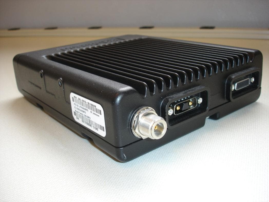
ATH2425M80
Nov 19, 2015DUAL BAND VHF AND 700/800 MHz MOBILE TRANSCEIVER
Equipment Class
TNB - Licensed Non-Broadcast Station Transmitter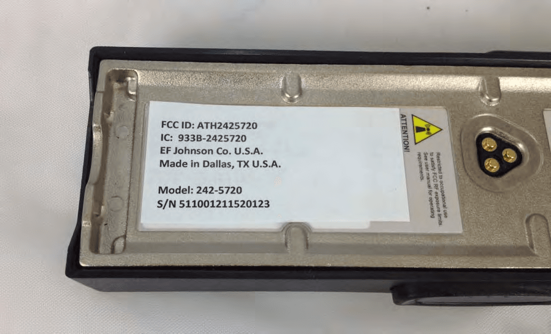
ATH2425720
Sep 30, 2012VP 600 UHF Land Mobile Radio Transceiver
Equipment Class
TNF - Licensed Non-Broadcast Transmitter Held to Face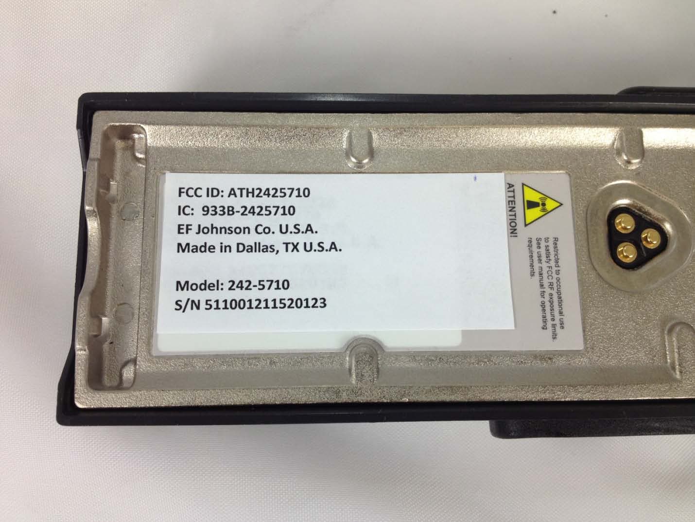
ATH2425710
Sep 16, 2012Portable VHF Push-To-Talk (PTT) Radio Transceiver
Equipment Class
TNF - Licensed Non-Broadcast Transmitter Held to Face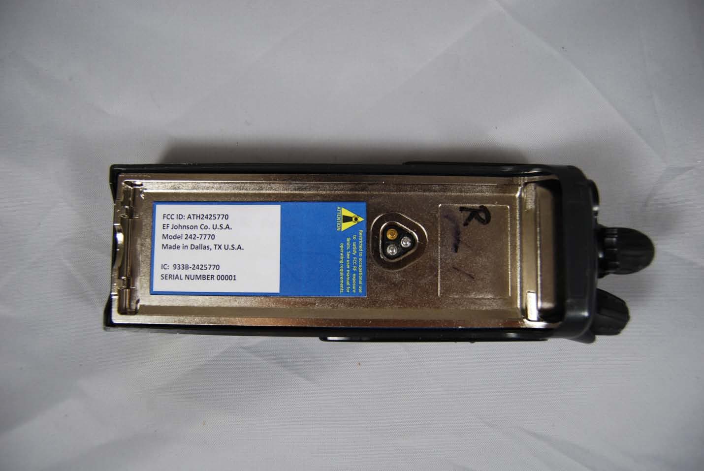
ATH2425770
Feb 09, 2012Vantage 700/800 MHz Portable Radio
Equipment Class
TNF - Licensed Non-Broadcast Transmitter Held to Face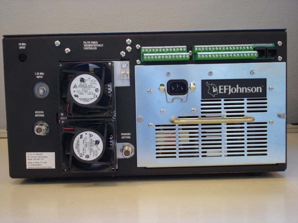
ATH2422607
Mar 07, 2010700 MHz LAND MOBILE REPEATER
Equipment Class
TNB - Licensed Non-Broadcast Station Transmitter