ATH2425330Digital Mobile Radio
E F Johnson Company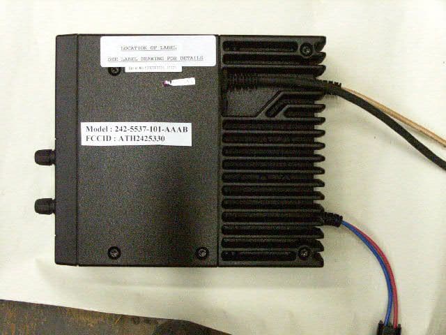
Click to zoom
Application Details
- Equipment Class
- TNB - Licensed Non-Broadcast Station Transmitter
- Date of Grant
- Oct 01, 2002
- Application Purpose
- Original Equipment
- Date of Application
- Oct 01, 2002
- Equipment Note
- Digital Mobile Radio
- Frequency Range
- 430.00000000 - 470.00000000
- Company
- E F Johnson Company
- Country
- United States
Documents & Files
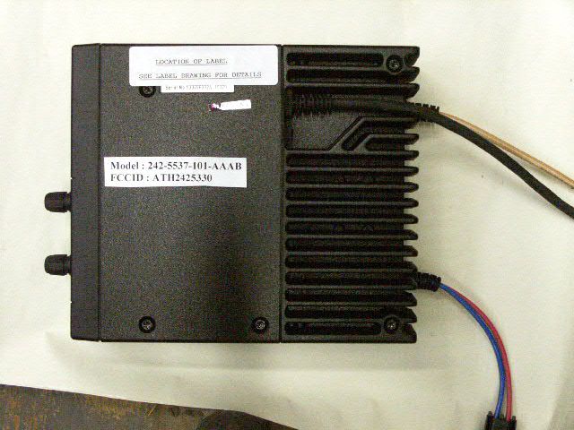
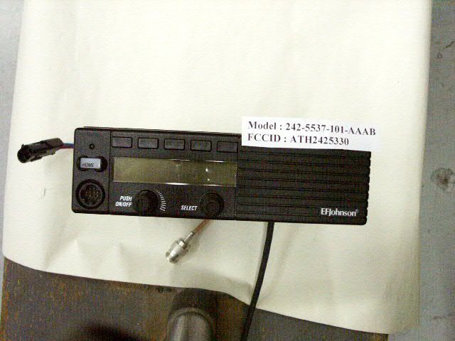
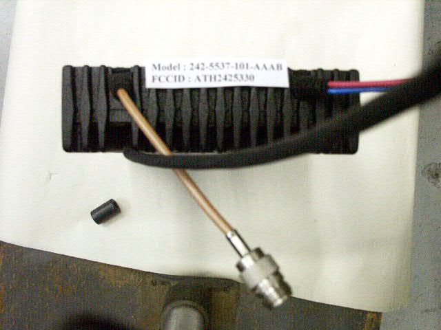
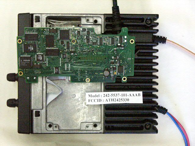
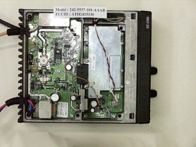
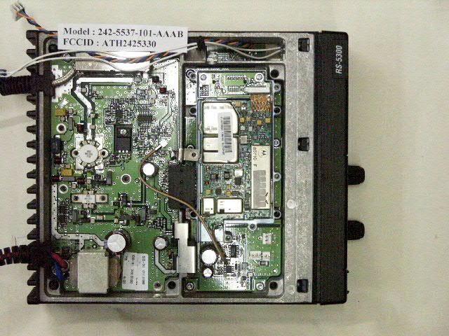
Document Text
Text extracted from the exhibit documents filed with the FCC. Open a document above to read the original.
Users Manual
DIGITAL/ANALOG MOBILE RADIO OPERATING MANUAL 5300 SERIES MOBILERADIO VHF/UHF/800 MHZ Analog and PROJECT 25 (DIGITAL) Conventional SMARTNET ® /SMARTZONE ® and Project 25 Trunked 13.6 VDC 10-50 or 50-100 Watts (VHF); 15 Watts (UHF); 10-35 Watts (800 MHz) Part No.: 242-53xx-xxx August 2002 Part Number: 002-5300-007CD PRELIMINARY 2 Revised August 2002 Part No. 001-5300-007CD-NR SAFETY INFORMATION SAFETY INFORMATION The FCC has adopted a safety standard for human expo- sure to RF energy. Proper operation of this radio under normal conditions results in user exposure to RF energy below the Occupational Safety and Health Act and Federal Communication Commission limits. WARNING DO NOT allow the antenna to touch or come in very close proximity with the eyes, face, or any exposed body parts while the radio is transmitting. To comply with FCC RF exposure limits, DO NOT operate the transmitter of a mobile radio when a person outside the vehicle is within one (1) meter of the antenna. To comply with FCC RF exposure limits, DO NOT operate the transmitter of a stationary radio (base station or marine radio) when a person is within one (1) meter of the antenna. DO NOT operate the radio in explosive or flammable atmospheres. The transmitted radio energy could trigger blasting caps or cause an explosion. DO NOT operate the radio without the proper antenna installed. DO NOT allow children to operate or play with this radio. NOTE: The above warning list is not intended to include all hazards that may be encountered when using this radio. This device complies with Part 15 of the FCC rules. Oper- ation is subject to the condition that this device does not cause harmful interference. In addition, changes or modi- fications to this equipment not expressly approved by EFJohnson could void the user’s authority to operate this equipment (FCC rules, 47CFR Part 15.19). FCC EXPOSURE LIMITS This mobile radio transceiver was tested by the manufacturer with an appropriate antenna in order to verify compliance with Maximum Permissible Exposure (MPE) limits set under Section 2.1091 of the FCC Rules and Regulations. The guidelines used in the evaluation are derived from Table 1 (B) titled “Limits For General Population/Uncontrolled Exposure” which is from FCC report OET bulletin #65. Table 2 lists the antenna whips and bases recom- mended for use in each frequency range. Each model of this radio was tested with the appropriate antenna listed. The antenna was mounted in the center of the roof of a domestically manufactured four-door passenger sedan. The radio manufacturer has determined that the user and service personnel should remain one (1) meter in distance away from the antenna when transmitting. By maintaining this distance, these individuals are not exposed to radio frequency energy or magnetic fields in excess of the guidelines set forth in Table 1. NOTE: Other antennas or installation configurations that have not been tested may not comply with FCC RF exposure limits and therefore are not recommended. Ta b l e 1 FCC Limits for Maximum Permissible Exposure (MPE) (B) Limits For General Population/Uncontrolled Exposure Frequency Range (MHz) Electric Field Strength (E) (V/m) Magnetic Field Strength (H) (A/m) Power Density (S) (mW/cm 2 ) 0.3-1.346141.63(100)* 1.34-30824/f2.19/f(180/f 2 )* 30-30027.50.0730.2 300-1500----f/1500 1500-100,000----1.0 f = Frequency in MHz*Plane-wave equivalent power density Table 2 Recommended Antenna Whips and Bases (Antenna Manufacturer - Antenna Specialists) FrequencyWhip Model No. Base Model No. 136-144 MHzASPJ1415KM220 144-152 MHzASPA1415KM220 152-162 MHzASPB1415KM220 162-174 MHzASPC1415KM220 400-430 MHzASPE1615KM220 430-470 MHzASPD1615KM220 470--512 MHzASPF1615KM220 806-869 MHzASPA1855KM220 890-960 MHzASPG1865KM220 53xx SERIES MOBILE OPERATING MANUAL VHF/UHF/800 MHz ANALOG CONVENTIONAL PROJECT 25 (DIGITAL) CONVENTIONAL AND TRUNKED SMARTNET ® /SMARTZONE ® ANALOG AND DIGITAL Copyright© 2002 by the E.F. Johnson Company The E.F. Johnson Company, which was founded in 1923, provides wireless communication systems solutions for public safety, government, and commercial customers. The company designs, manufactures, and markets conventional and trunked radio systems, mobile and portable subscriber radios, repeaters, and Project 25 digital radio products. E.F. Johnson is a wholly owned subsidiary of EFJ, Inc., formerly Transcrypt International, Inc. Viking Head/EFJohnson logo and Call Guard ® are trademarks of the E.F. Johnson Company. SMARTNET ® , SmartZone ® , SecureNet ™ , Call Alert ™ , Enhanced Private Conversation ™ , and Private Conversation II ™ are trademarks of Motorola, Inc. All other company and/or product names used in this manual are trademarks and/or registered trademarks of their respective manufacturer. The IMBE™ voice coding technology embodied in this product is protected by intellectual property rights including patent rights of Digital Voice Systems, Inc. LAND MOBILE PRODUCT WARRANTY - The manufacturer’s warranty statement for this product is available from your product supplier or from E.F. Johnson Company, 299 Johnson Avenue, Box 1249, Waseca, MN 56093-0514. Phone (507) 835-6222. Information in this manual is subject to change without notice. 4 Revised August 2002 Part No. 001-5300-007CD-NR TABLE OF CONTENTS TABLE OF CONTENTS SAFETY INFORMATION FCC Exposure Limits . . . . . . . . . . . . . . . . . . . . . . . 2 1FEATURES 1.1General Features . . . . . . . . . . . . . . . . . . . . . . . . . . . 6 1.2Conventional Features . . . . . . . . . . . . . . . . . . . . . . . 6 1.3SMARTNET™ II/SmartZone® Features . . . . . . . . 6 1.4Project 25 Trunked Features . . . . . . . . . . . . . . . . . . 6 2CONTROLS AND DISPLAY 2.1Front Panel Controls . . . . . . . . . . . . . . . . . . . . . . . . 7 2.2Rear Panel Jacks . . . . . . . . . . . . . . . . . . . . . . . . . . . 8 2.3Display . . . . . . . . . . . . . . . . . . . . . . . . . . . . . . . . . . . 8 3GENERAL OPERATION 3.1Turning Power …
Text truncated - open the document above for the full version.
Attestation Statements
Waseca Office: E.F. Johnson Company • 299 Johnson Ave., P.O. Box 1249 • Waseca, MN 56093-0514 • 800-328-3911 • 507-835-6222 • Fax 507-835-8356 www.efjohnson.com August 19, 2002 Federal Communications Commission EQUIPMENT AUTHORIZATION BRANCH 7435 Oakland Mills Road Columbia, MD 21046 Re: Programming Capability Gentlemen: Reference part 90.203(e), frequency programming capability. The end user will not be able to program the channel frequencies. A service shop or authorized agent using a special programming cable and computer software can program the allowed TX/RX frequencies. The end user can only select from the preprogrammed channels using the channel select knob. The software and programming cable are not available to the end user. Sincerely, John Oblak Chief Engineer E.F. Johnson Co.
Operational Description
3-1 Revised July 2002 Part No. 001-5300-005 OPERATION SECTION 3 OPERATION Figure 3-1 Front Panel Controls Option Switches (6) Display Microphone PTT Switch Speaker Select Switch On-Off/ Volum e Multi-function Indicator 3.1 FEATURES 3.1.1 GENERAL FEATURES •Each channel is programmable for one of the following operating modes: – Conventional analog or Project 25 (digital) – SMARTNET™/SmartZone® trunked analog or Project 25 (digital) •Up to 16 zones with up to 16 channels each programmable (256 channels total) •Large liquid crystal display (LCD) with backlight •Six option switches that can be programmed with a different function for each operating mode (conven- tional and SMARTNET) •User selectable high and low power output •Standard scan mode •Operation on both narrow and wideband channels •Time-out timer 3.1.2 CONVENTIONAL FEATURES •Each channel selects a different radio channel and squelch coding •Repeater talk-around •Normal/Selective squelch selected by microphone hanger or option switch •Carrier, tone (CTCSS), or digital (DCS) controlled Call Guard ® squelch on analog channels. NAC and group IDs on Project 25 channels •Penalty and conversation timers •Priority channel sampling when scanning •Busy channel lockout (transmit disable on busy) •ANI (Automatic Number Identification) •SecureNet™ secure communication available on analog channels or SecureNet DES-OFB on Project 25 channels •Individual ID calls on Project 25 channels •Emergency switch 3.1.3 SMARTNET/SMARTZONE FEATURES •Channels select talk groups •Private and telephone* calls •Emergency alarms to alert dispatcher of emergency conditions •Emergency calling for high priority system access •Failsoft* operation on a predefined conventional channel if trunked system fails * Available with future release. Contact your EFJohnson account manager for more information. OPERATION 3-2 Revised July 2002 Part No. 001-5300-005 •Priority group calls detected while listening to other group calls •Call alert (send and receive pages) •Predefined messages (up to 16) can be sent to a dispatcher •Predefined status conditions (up to 8) can be sent to a dispatcher •Dynamic regrouping* (dispatcher can automatically gather users on a channel to receive a message) •Roaming (SmartZone only) •SecureNet™ secure communication available on analog channels, SecureNet DES-OFB available on Project 25 channels NOTE: The availability of many of the preceding features is controlled by transceiver programming (see Section 4) and the capabilities of the radio system being accessed. 3.2 CONTROLS AND DISPLAY NOTE: The controls and indicators described in the following information are shown in Figure 3-1. 3.2.1 FRONT PANEL CONTROLS On-Off/Volume - Pressing this control turns power on and off, and rotating it sets the volume level. Select Switch - Selects zones/channels and is also used for other functions such as selecting names from a call list. When selecting zones/channels, a bar above the zone or channel display indicates which is currently being changed (see Figure 3-3). To switch this bar between displays, press this switch, and to select zones or channels, rotate it (see Section 3.3.6). Multi-function Indicator - This is a two-color LED that indicates the following: Red (constant) - Transmitter keyed (PTT switch pressed). Green (constant) - Busy condition (carrier detected in receive mode). Option Switches - Each of the six options switches on the front panel (including the one located to the left of the display) can be programmed to control a function. Different functions can be programmed for each oper- ating mode (conventional and SMARTNET). There- fore, up to 12 different functions can be programmed. Refer to Section 3.4.1 for more information. Speaker - An internal 16-ohm, 5-watt speaker is located behind the grille. An optional 4-ohm, 12-watt external speaker may be used if desired. The internal speaker is disabled when an external speaker is used. PTT Switch - This push-button switch on the micro- phone is pressed to talk (key the transmitter) and released to listen. Figure 3-2 Rear Panel Jacks 3.2.2 REAR PANEL JACKS DC Power Jack - Connection point for a nominal 12- volt, negative ground power source (see Figure 3-2). Antenna Jack - Type N jack for connecting the 50-ohm antenna. Accessory Jack - Black connector for connecting optional accessories such as an external speaker and ignition sense line (see Section 2.4). Remote Control Unit Jack - Connection point for a remote control unit or handheld control unit (if used). This cable is optional with front-mount models. Siren Control Jack (Not Shown) - Yellow/orange connector similar to accessory jack for connecting siren controller (if used). Remote Control Unit Jack Accessory Jack Antenna Jack DC Power Jack * Available with future release. Contact your EFJohnson account manager for more information. OPERATION 3-3 Revised July 2002 Part No. 001-5300-005 Figure 3-3 Front Panel Display Telephone/Special Call Mode Enabled Encryption 10-Character Alphanumeric Display Zone No. Status Display Chnl No. Scan Edit Mode 3.2.3 DISPLAY Zone Number - Indicates the currently selected zone from 1 up to 16 (see Figure 3-3). A zone is a collection of channels that can be any combination of the conven- tional and SMARTNET/SmartZone types (see Section 1.2.4). Channel Number - Indicates the currently selected radio channel (conventional) or talk group (SMARTNET/SmartZone). Alphanumeric Display - This 10-character area of the display indicates the alias (alpha tag) for the selected channel. It may also display other information such as the channel frequency (conventional) if certain option switches are programmed. It also displays various status and error messages. Status Display - These two characters indicate the following status information: - This symbol in the left position indicates that the displayed channel is in the scan list (scanned normally). - A “P” in the left position indicates that the selected conventional chan…
Text truncated - open the document above for the full version.
Parts List/Tune Up Info
7-1 Revised July 2002 Part No. 001-5300-005 PA R T S L I S T SECTION 7 PARTS LIST Ref No.DescriptionPart No. CHASSIS, HARDWARE, AND MISCELLANEOUS A 102 Front panel assembly (frt mt) (see separate listing on page 7-19) 023-5300-710 A 200 Interface board assembly (see separate listing which follows) 023-5300-201 A 300 Receiver/exciter assembly (VHF) (see separate listing on page 7-2) 023-5317-212 Receiver/exciter assembly (UHF) (see listing on page 7-2) 023-5337-202 Receiver/exciter assembly (800 MHz) (see listing on page 7-2) 023-5387-202 A 301 Accessory pigtail cable (internal) 597-2002-230 A 302Remote/acc pigtail cable (internal) 597-2002-249 A 400 Logic board assembly (see separate listing on page 7-13) 023-5300-411 A 500 PA board assembly (VHF) (see separate listing on page 7-3) 023-5315-501 PA board assembly (UHF) (see separate listing on page 7-10) 023-5335-511 PA board assembly (800 MHz) (see separate listing on page 7-10) 023-5385-501 CH 101 Chassis, metal standard models015-0970-001 Chassis, metal 100W models015-0970-011 EP 001 No. 6 terminal lug 586-0005-106 EP 002 Ferrite bead, .375 x .375 517-2002-003 EP 003 Ferrite block (for J200)517-2002-020 EP 920 Snubber, bottom shield018-1134-136 HW 001 Captive screw, cover 537-9007-045 HW 002 Screw, 6-32 x 5/16” Torx 575-0006-010 HW 003 Plug, option (in unused chass hole) 032-0792-075 HW 004 Audio amp U1 clip 017-9700-001 HW 005 O-ring, 1/8” x 1/4” cover screw574-2002-001 HW 006 Nylon washer, cover screw596-4408-015 HW 007 Split rubber grommet 1/8”ID 574-0002-015 HW 009 Flat washer, cover screw596-9408-009 HW 010 Screw, 4-40 x 5/16” phil pan hd 575-0604-010 HW 011 Washer, No 4 split lock596-1304-008 HW 012 Washer, No. 4 split lock 596-1304-008 HW 020 1/4” x 1.20” x 1.90” urethane pad 018-1007-250 HW 150 Screw, 4-40 x 5/16 phil pan hd 575-0604-010 HW 151 Screw, 6-32 x 3/8 phil flat hd575-8206-012 HW 152 Screw, 8-32 x 3/8 hex socket hd575-9076-012 HW 202 Screw, 4-40 x 1-1/8 mach pan hd 575-1604-036 HW 203 Screw, 2-56 x 1/8 pan hd 575-1602-004 HW 204 Screw, 4-40 x 1/4 pan hd 575-1604-008 J 002 RF – PA board connector 515-9006-110 J 200Connector, 28-pin inline header515-7181-038 MP 002 Cover, top black 015-0970-007 MP 003 Cover, bottom black 015-0970-009 MP 004 Gasket, blank front panel (remote) 032-0792-068 MP 005 Front panel, blank (remote)032-0792-005 MP 151 Cover, 100W heatsink017-9700-007 MP 152 Gasket, 100W heatsink cover018-1136-142 MP 153 Gasket, 100W heatsink coax018-1136-144 MP 156 Gasket, top cover 018-1136-136 MP 157 Gasket, bottom cover 018-1136-134 MP 300 Foam tape, dbl side 574-3002-013 MP501 Shield, coax gnd (800 MHz)017-2226-017 MP 502 Shield, low-pass filter (800 MHz) 017-2226-036 MP 503 Grounding finger (800 MHz)537-5001-010 MP 504 Grounding clip (800 MHz)537-5001-004 MP 505 Grounding clip (rx/ex assy)017-9700-003 Shield (800 MHz)017-2227-063 MP 506 Transistor ground tab (800 MHz)017-2225-527 MP 601 Shield, low-pass filter 017-9700-000 NP 001 Label, RS 5300559-5300-100 NP 002 Label, Johnson559-9001-310 W 103 Cable assy, display - logic bd 023-5300-025 W 501 Pwr pigtail cable assembly, std PA 597-2002-235 W 502 RF pigtail cable assembly, std PA597-2002-240 INTERFACE BOARD Part No. 023-5300-201 C 002 470 μF 25V electrolytic 510-4064-471 C 003 100 μF 25V electrolytic 510-4425-101 C 004 1.0 μF 10V tantalum smd 510-2624-109 C 005 .1 μF ±5% X7R 50V cer smd 510-3609-104 Ref No.DescriptionPart No. Interface BoardChassis, Hardware, Misc. PARTS LIST 7-2 Revised July 2002 Part No. 001-5300-005 C 006 .1 μF ±5% X7R 50V cer smd 510-3609-104 C 007 .1 μF ±5% X7R 50V cer smd 510-3609-104 C 009 470 pF ±5% NPO cer smd 510-3602-471 C 010 .1 μF ±10% X7R 50V cer smd 510-3606-104 C 011 .1 μF ±10% X7R 50V cer smd 510-3606-104 C 012 .1 μF ±10% X7R 50V cer smd 510-3606-104 C 013 4.7 μF 10V tantalum smd 510-2624-479 C 014 4.7 μF 10V tantalum smd 510-2624-479 C 015 .01 μF ±5% X7R 50V cer smd 510-3609-103 CR 001 10V zener SOT-23 523-2016-100 CR 002 Switching diode SOT-23 523-1504-002 J 201 Connector, 20-pin 515-7111-230 J 202 Connector, 30-pin 515-7106-430 P 100 Header, 2-pin friction lock 515-9031-201 P 101 Header, 3-pin friction lock 515-9031-202 PC 201 PC board, interface035-5300-200 Q 001 NPN general purpose 576-0003-658 Q 002 NPN general purpose 576-0003-658 R 002 2.2 ohm ±5% 1W smd 569-0175-229 R 003 10k ohm ±5% 1/8W smd 569-0105-103 R 004 47k ohm ±5% 1/8W smd 569-0105-473 R 005 10k ohm ±5% 1/8W smd 569-0105-103 R 006 7.5k ohm ±5% 1/8W smd 569-0105-752 R 008 1k ohm ±5% 1/8W smd 569-0115-102 R 009 1k ohm ±5% 1/8W smd 569-0115-102 R 010 1k ohm ±5% 1/8W smd 569-0115-102 R 011 10k ohm ±1% 1/8W smd 569-0111-401 R 012 35.7k ohm ±1% 1/8W smd 569-0111-454 R 013 10k ohm ±5% 1/8W smd 569-0115-103 R 014 10k ohm ±5% 1/8W smd 569-0115-103 R 015 Zero ohm jumper 569-0115-001 R 016 10k ohm ±5% 1/8W smd 569-0115-103 R 017 3k ohm ±5% 1/8W smd 569-0115-302 R 018 10k ohm ±5% 1/8W smd 569-0115-103 R 019 Zero ohm jumper 569-0115-001 R 020 10k ohm ±5% 1/8W smd 569-0115-103 R 021 10k ohm ±5% 1/8W smd 569-0115-103 R 022 10k ohm ±5% 1/8W smd 569-0105-103 U 001 Audio amp, 22W TDA1519 544-2004-003 U 002 Voltage regulator, adjust TK11900 544-2603-093 Ref No.DescriptionPart No. U 003 Op amp, dual LM2904 544-2019-004 U 004 Digital potentiomtr, 2-ch AD8402 544-0004-213 RECEIVER/EXCITER ASSEMBLY Part No. 023-53x7-202/-212 A 001 Interconnect board assy, unrevised (see separate listing which follows) 023-5300-050 Interconnect board assy, revised (see separate listing which follows) 023-5300-055 A 002 RF board assembly, VHF unrevised 585-0400-003 RF board assembly, VHF revised585-5100-003 RF board assy, UHF unrevised587-0400-005 RF board assy, UHF revised585-5100-005 RF board assy, 800 MHz unrevised 587-5000-003 RF board assy, 800 MHz revised585-5100-009 A 216Flex circuit, revised RF to logic bd 035-5100-050 EP 001 0.2 x 0.2 fish paper018-1080-020 HW 001 Screw, 2-56 x 3/16” pan hd 575-1602-006 HW 002 Screw, 4-40 x 1/4” pan hd 575-1604-008 HW 003 Lockwasher, internal 596-2102-006 …
Text truncated - open the document above for the full version.
Parts List/Tune Up Info
6-1 Revised March 2002 Part No. 001-5300-004 ALIGNMENT PROCEDURE SECTION 6 ALIGNMENT PROCEDURE Figure 6-1 Alignment Setup Remote Programming Interface (RPI) To Battery To Antenna To Ign Sense Cable Assembly Part No. 023-5300-005 SINAD Meter Part No. 023-5300-000 NOTE: The ignition sense line must be connected to +13.8V for the radio to operate. Communication Monitor 6.1 GENERAL 6.1.1 INTRODUCTION The following alignment procedure should be performed if repairs are made that could affect the factory alignment or if adjustments may have changed for some other reason. To perform transceiver alignment, a PC-compat- ible computer, Remote Programming Interface (RPI) Part No. 023-5300-000, and PCTune software are required (see Table 1-1). Earlier RPIs, such as Part No. 023-9800-000 or 023-9750-000, cannot be used. Refer to Section 4.1.3 for more RPI information. The programming setup is shown in Figure 6-1. All adjustments are set digitally using the computer. Therefore, there is no need to disassemble the transceiver to access adjustment points. In addi- tion, audio test signals are generated internally, so an audio generator is not required. The required test equipment is shown in Figure 6-1. 6.1.2 TUNE SOFTWARE General The PCTune software is a Windows ® program. Minimum software and hardware requirements are as follows: •Windows ® 95/98/NT/2000 (3.1 cannot be used) •Pentium ® processor or equivalent •16 MB of RAM •A hard disk drive with at least 3 MB of free space •A CD-ROM drive •An available serial port Software Installation Proceed as follows to install this software: 1. Close all applications that are currently running (other than Windows). 2. Insert the disk containing the PCTune software in drive. ALIGNMENT PROCEDURE 6-2 Revised March 2002 Part No. 001-5300-004 Figure 6-2 PCTune Main Screen Menu Bar To o l B a r Radio Information Tuning Instructions Tuning Hints 3. From the Windows taskbar, choose RUN and open SETUP.EXE on the drive being used. Alternatively, use File Explorer and double click SETUP.EXE. 4. Follow the instructions on the screen. The program is automatically loaded on the hard drive and start- up shortcuts or groups are created. Starting PCTune Select Start in the taskbar, then Programs > PCTune > PCTune. Exiting PCTune Select File > Exit or click the or button. On-Line Help On-line help is not available at this time. 6.2 MAIN SCREEN 6.2.1 GENERAL The main PCTune screen is shown in Figure 6-2. The main parts of this screen are as follows: Menu Bar - Used to select the menus described in Sections 6.3.1-6.3.4. To o l B a r - These buttons are used to quickly select functions as follows: - Exits the program same as File > Exit. - Reads and displays the current parameters programmed in the radio same as Radio > Read Tune Parameters (see Section 6.3.3). - Selects the complete radio tune mode the same as Radio > Tune > Complete. - Selects the partial radio tune mode which allows manual selection of each adjustment same as Radio > Tune > Partial. Radio Information Radio Type - The Radio Series selected by the Radio > Series menu function (see Section 6.3.3). Radio Band - The radio frequency band and power output selected by the Radio > Set Band menu function (see Section 6.3.3). ALIGNMENT PROCEDURE 6-3 Revised March 2002 Part No. 001-5300-004 Serial Number - The electronic serial number of the radio. Software Version - The first number is the version number of the DSP (U12) software, and the second number is the version number of the ARM processor (U6) software. Tuning Options When the tuning mode has been enabled by Radio > Tune Complete/Partial, this part of the screen displays the current adjustment value and up/down buttons for changing the value. In addition, when “Partial” is selected, adjust- ments can be individually selected by clicking the applicable button (see Section 6.3.3). 6.3 MENU BAR DESCRIPTION 6.3.1 FILE MENU Selecting File > Exit closes PCTune as just described. 6.3.2 SERIAL MENU Port - Selects the serial port used by the RPI (see Section 6.4.1). Baud - Selects the data rate used for communica- tion with the transceiver. Select “19200” as shown above. 6.3.3 RADIO MENU Series - Selects the particular radio being tuned. The default may be “5300 Series”, so if one of the other models is being tuned, this may need to be selected each time PCTune is started. Read Tune Parameters - Selecting this function or clicking the button reads the tune parameters currently programmed in the transceiver and displays them in the following screen. Read Tune Parameters Screen NOTE: The preceding Read Tune Parameters screen should be used for reference only. Adjust- ment of values should be done only by using the Complete or Partial Tune functions. Click the tab on top to display the desired parame- ters. Checking the box on the bottom displays the values as hexadecimal instead of decimal. Parameters can be changed by entering a value in the appropriate box. Clicking “Default” programs ALIGNMENT PROCEDURE 6-4 Revised March 2002 Part No. 001-5300-004 default values, clicking “OK” closes the screen and saves the values entered, and clicking “Cancel” closes the screen without saving any values. Tune - Selecting “Complete” or clicking the button automatically steps through all tuning steps, and selecting “Partial” or clicking the button allows the tuning steps to be selected manually in the “Tuning Options” box. Reset Radio - Resets the radio control logic. This can be used, for example, to change the radio series or band or exit an adjustment before it is complete. Erase EEPROM - Selecting “Params Only” deletes the parameters that are programmed by PCCon- figure as described in Section 3. If “Complete” is displayed, DO NOT SELECT IT. This deletes parameters that can be programmed at the factory only. Therefore, the transceiver would have to be returned to the factory to make it operational again. Set Band - Selects the operating band and power output of the radio being tuned and r…
Text truncated - open the document above for the full version.
RF Exposure Info
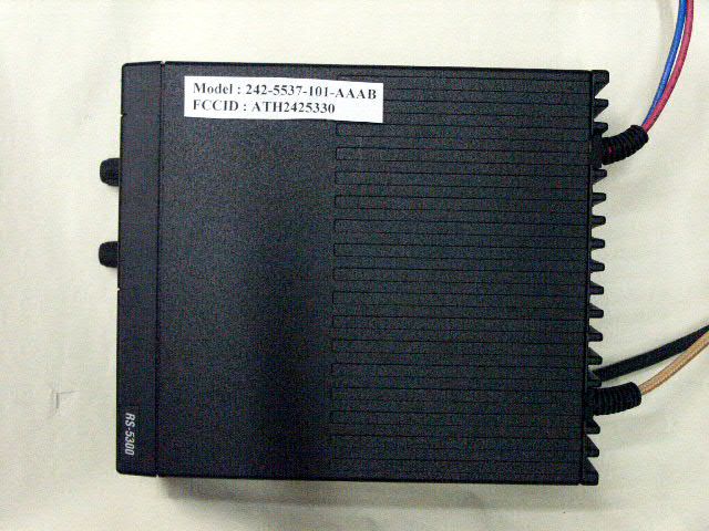
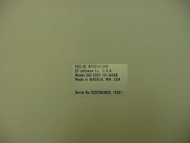
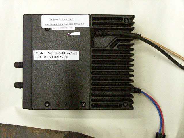
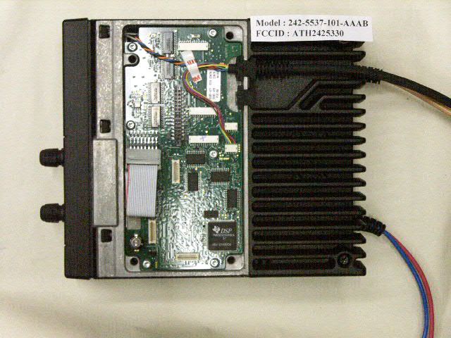
FCC ID: ATH2425330 MFA p0290002, d0290024 ENVIRONMENTAL ASSESSMENT for MOBILES/FIXED BASE STATION for FCC ID: FCC ID: ATH2425330 Model:242-5337-101-AAAB to FEDERAL COMMUNICATIONS COMMISSION 47 CFR 1.1310 (MPE) Radiofrequency Radiation Exposure Limits DATE OF REPORT: September 11, 2002 ON THE BEHALF OF THE APPLICANT: E. F. Johnson Company AT THE REQUEST OF: P.O. 161969 E. F. Johnson Company, 299 Johnson Ave. Waseca, MN 56093-0514 Attention of: (507) 835-6579; FAX: -6666 John Oblak, Director, Radio Products Development E-mail: [email protected] SUPERVISED BY: Morton Flom, P. Eng. FCC ID: ATH2425330 MFA p0290002, d0290024 TABLE OF CONTENTS RULEDESCRIPTIONPAGE . Test Report 1 . Identification of the Equipment Under Test 2 . Standard Test Conditions and Engineering Practices 4 1.1310 Environmental Assessment 5 FCC ID: ATH2425330 MFA p0290002, d0290024 PAGE NO.1of9. Required information per ISO/IEC Guide 25-1990, paragraph 13.2: a) TEST REPORT (SUPPLEMENTAL) b) Laboratory: (FCC: 31040/SIT) (Canada: IC 2044) M. Flom Associates, Inc. 3356 N. San Marcos Place, Suite 107 Chandler, AZ 85225 c) Report Number: d0290024 d) Client: E. F. Johnson Company, 299 Johnson Ave. Waseca, MN 56093-0514 e) Identification: 242-5337-101-AAAB FCC ID: ATH2425330 Description: UHF Transceiver f) EUT Condition: Not required unless specified in individual tests. g) Report Date: September 11, 2002 EUT Received: September 4, 2002 h, j, k): As indicated in individual tests. i) Sampling method: No sampling procedure used. l) Uncertainty: In accordance with MFA internal quality manual. m) Supervised by: Morton Flom, P. Eng. n) Results: The results presented in this report relate only to the item tested. o) Reproduction: This report must not be reproduced, except in full, without written permission from this laboratory. FCC ID: ATH2425330 MFA p0290002, d0290024 PAGE NO.2of9. IDENTIFICATION OF THE EQUIPMENT UNDER TEST (EUT) NAME AND ADDRESS OF APPLICANT: E. F. Johnson Company 299 Johnson Ave. Waseca, MN 56093-0514 MANUFACTURER: Applicant FCC ID: ATH2425330 MODEL NO: 242-5337-101-AAAB DESCRIPTION: UHF Transceiver TYPE OF EMISSION: 16K0F3E, 11K0F3E, 8K10F1E FREQUENCY RANGE, MHz: 430 to 470 POWER RATING, Watts: 10to20 Switchable x Variable N/A MODULATION: AMPS TDMA CDMA x OTHER ANTENNA: HELICAL MONOPOLE WHIP x OTHER NOTE: For RF Safety test antenna gain taken at the upper range of expected gain (i.e. 0 dBd) and RF Power set to highest nominal power across all channels. FCC ID: ATH2425330 MFA p0290002, d0290024 PAGE NO.3of9. M. Flom Associates, Inc. is accredited by the American Association for Laboratory Association (A2LA) as shown in the scope below. "This laboratory is accredited by the American Association for Laboratory Accreditation (A2LA) and the results shown in this report have been determined in accordance with the laboratory's terms of accreditation unless stated otherwise in the report." Should this report contain any data for tests for which we are not accredited, or which have been undertaken by a subcontractor that is not A2LA accredited, such data would not covered by this laboratory's A2LA accreditation. FCC ID: ATH2425330 MFA p0290002, d0290024 PAGE NO.4of9. STANDARD TEST CONDITIONS and ENGINEERING PRACTICES Except as noted herein, the following conditions and procedures were observed during the testing: In accordance with ANSI C63.4-1992/2000, section 6.1.9, and unless otherwise indicated in the specific measurement results, the ambient temperature of the actual EUT was maintained within the range of 10°to 40°C (50°to 104°F) unless the particular equipment requirements specify testing over a different temperature range. Also, unless otherwise indicated, the humidity levels were in the range of 10% to 90% relative humidity. Prior to testing, the EUT was tuned up in accordance with the manufacturer's alignment procedures. All external gain controls were maintained at the position of maximum and/or optimum gain throughout the testing. Measurement results, unless otherwise noted, are worst case measurements. FCC ID: ATH2425330 MFA p0290002, d0290024 PAGE NO.5of9. Name of test:Environmental Assessment Specification:FCC: 47 CFR 1.1310 Measurement Guide:ANSI/IEEE C95.1 1992 Test Equipment:Maximum Permissible Exposure (MPE) measurement system, consisting of: Narda 8717-1174R, Radiation meter Narda 8761D, E-field probe (300 kHz – 3 GHz) (Calibrated Nov-98) Measurement Procedure: 1. The following measurements were performed with a Narda probe using ANSI/IEEE C95.1 as a guide. 2. Prior to making any measurements, the measurements system was calibrated in accordance with the manufacturer’s procedures. 3. The EUT’s radiating element (antenna) was placed ona1mtall table for ease of testing. For equipment normally operated on a metal surface, a ground plane was used. 4. The remaining equipment necessary to operate the EUT was maintained at a distance from the measurement arrangement suitable to minimize interference with the measurements. 5. The minimum safe distance was calculated from the formula Power Density = EIRP / 4πR 2 (Peak Watts/m 2 ). The calculation is shown with the measurement data. 6. With the EUT operating at maximum power, a …
Text truncated - open the document above for the full version.
Contact Information
Applicant
Karthik Rangarajan(SR VP Engineering)
Test Firm
M. Flom Associates, Inc.Morton Flom
Technical Specifications
| # | Rule Parts | Frequency Range | Power Output | Emission | Tolerance |
|---|---|---|---|---|---|
| 6 | 90,95A | 430 MHz - 470 MHz | 20 W | 16K0F3E | 5 ppm |
Other Applications from E F Johnson Company
ATH2425M80
Nov 19, 2015DUAL BAND VHF AND 700/800 MHz MOBILE TRANSCEIVER
Equipment Class
TNB - Licensed Non-Broadcast Station Transmitter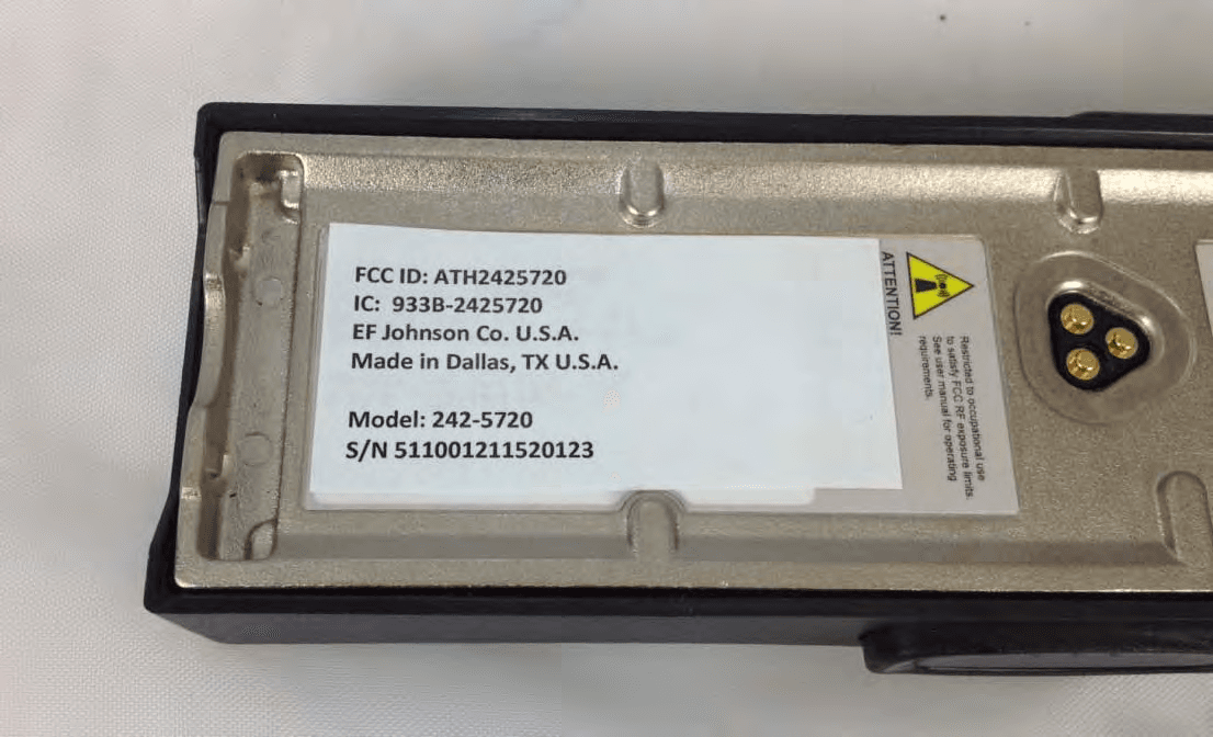
ATH2425720
Sep 30, 2012VP 600 UHF Land Mobile Radio Transceiver
Equipment Class
TNF - Licensed Non-Broadcast Transmitter Held to Face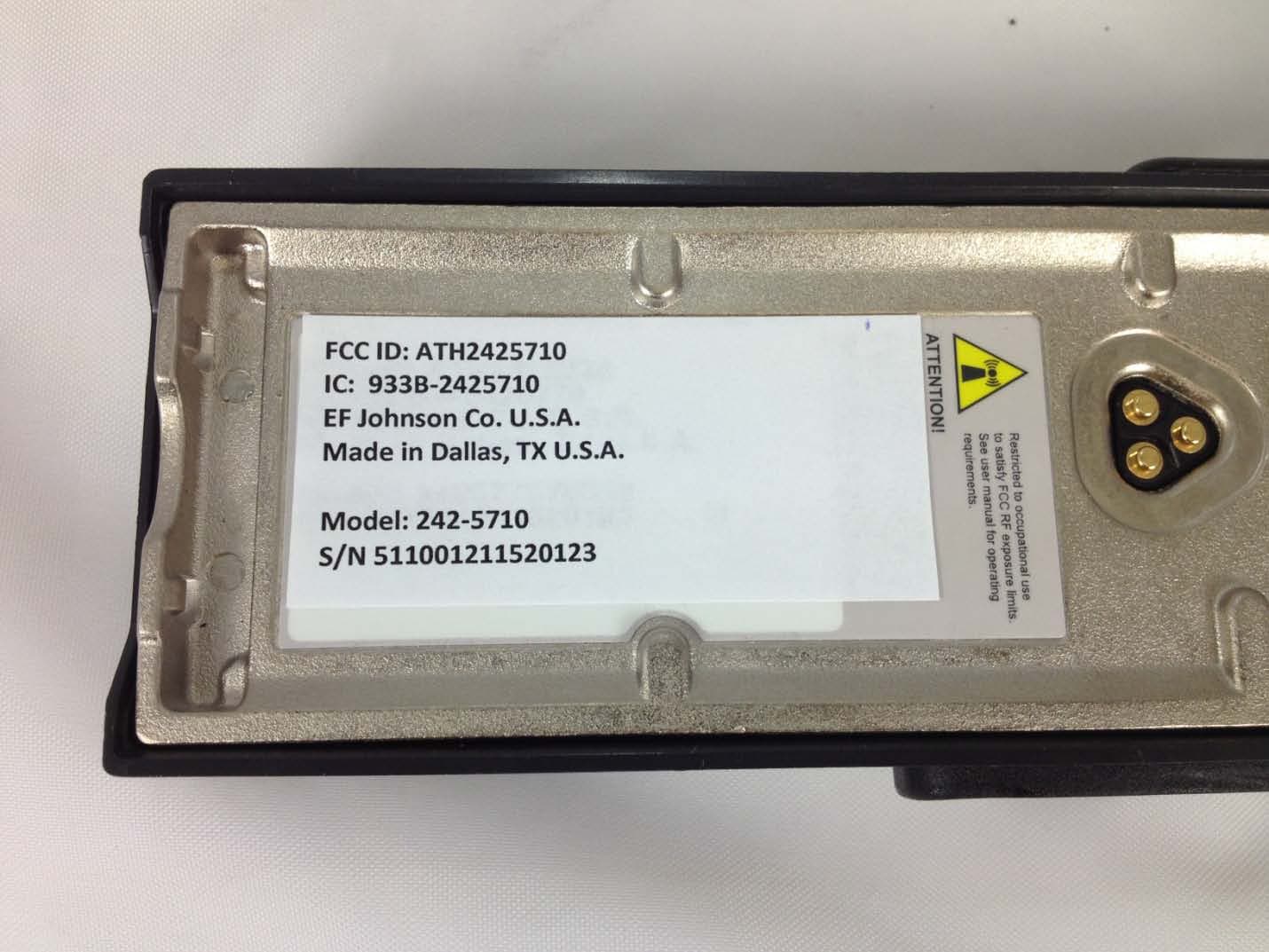
ATH2425710
Sep 16, 2012Portable VHF Push-To-Talk (PTT) Radio Transceiver
Equipment Class
TNF - Licensed Non-Broadcast Transmitter Held to Face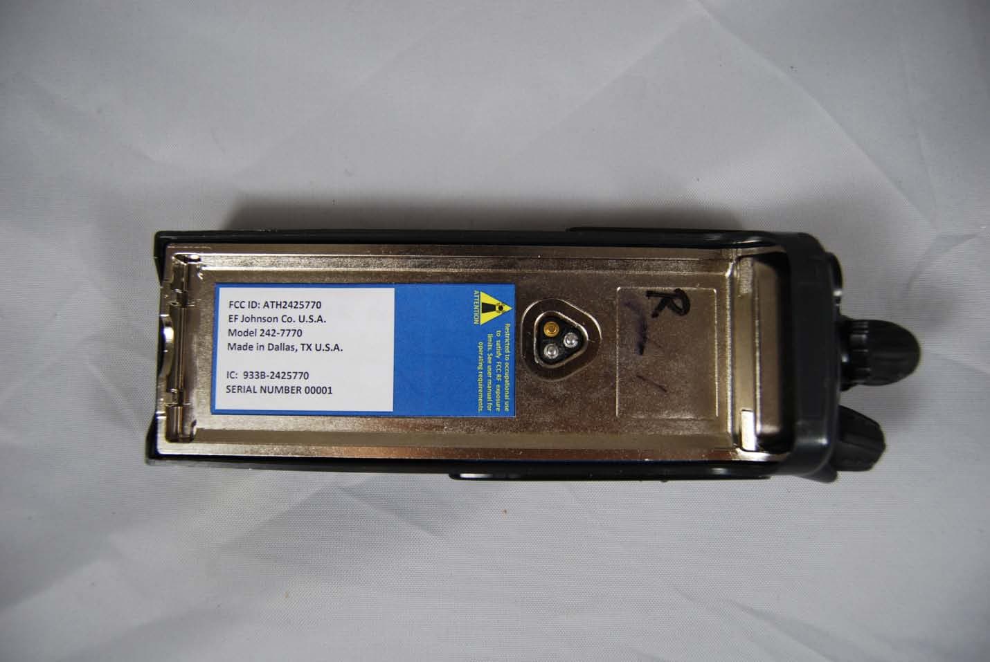
ATH2425770
Feb 09, 2012Vantage 700/800 MHz Portable Radio
Equipment Class
TNF - Licensed Non-Broadcast Transmitter Held to Face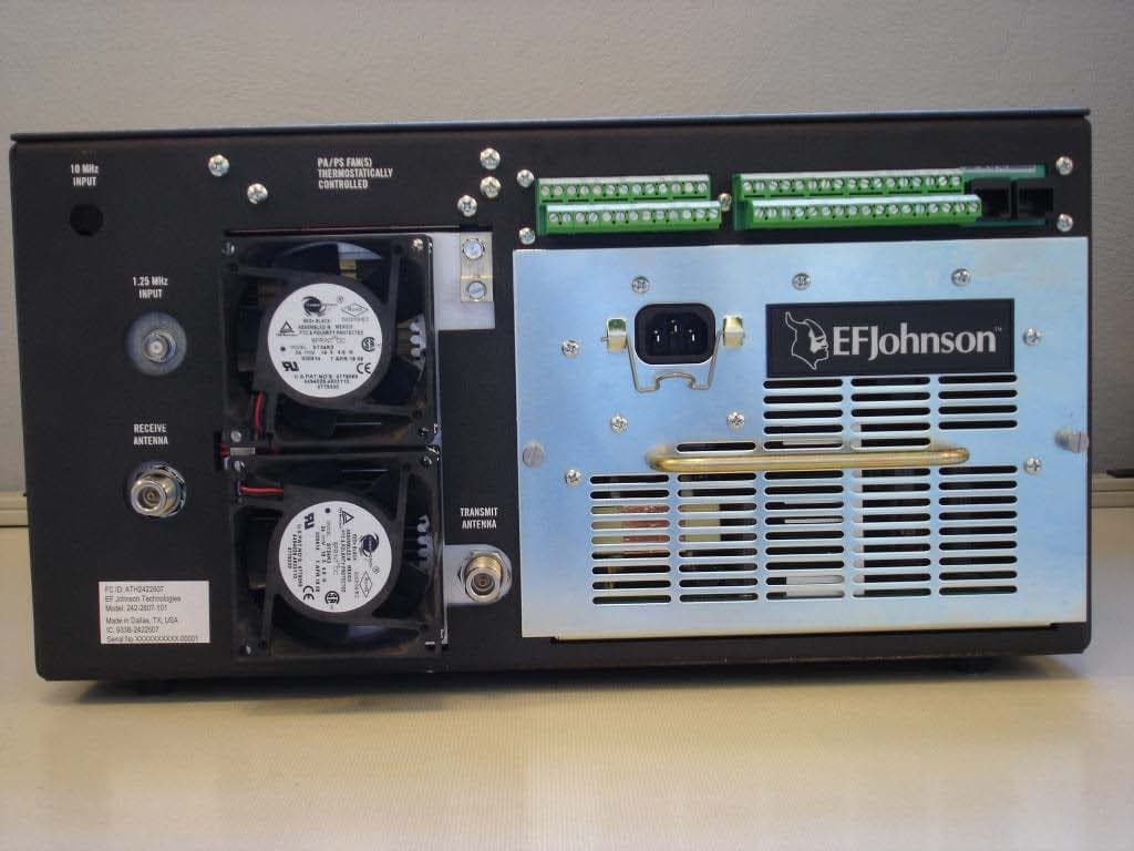
ATH2422607
Mar 07, 2010700 MHz LAND MOBILE REPEATER
Equipment Class
TNB - Licensed Non-Broadcast Station Transmitter