ATH2427240UHF FM Handheld Transceiver Held-to-face
E F Johnson Company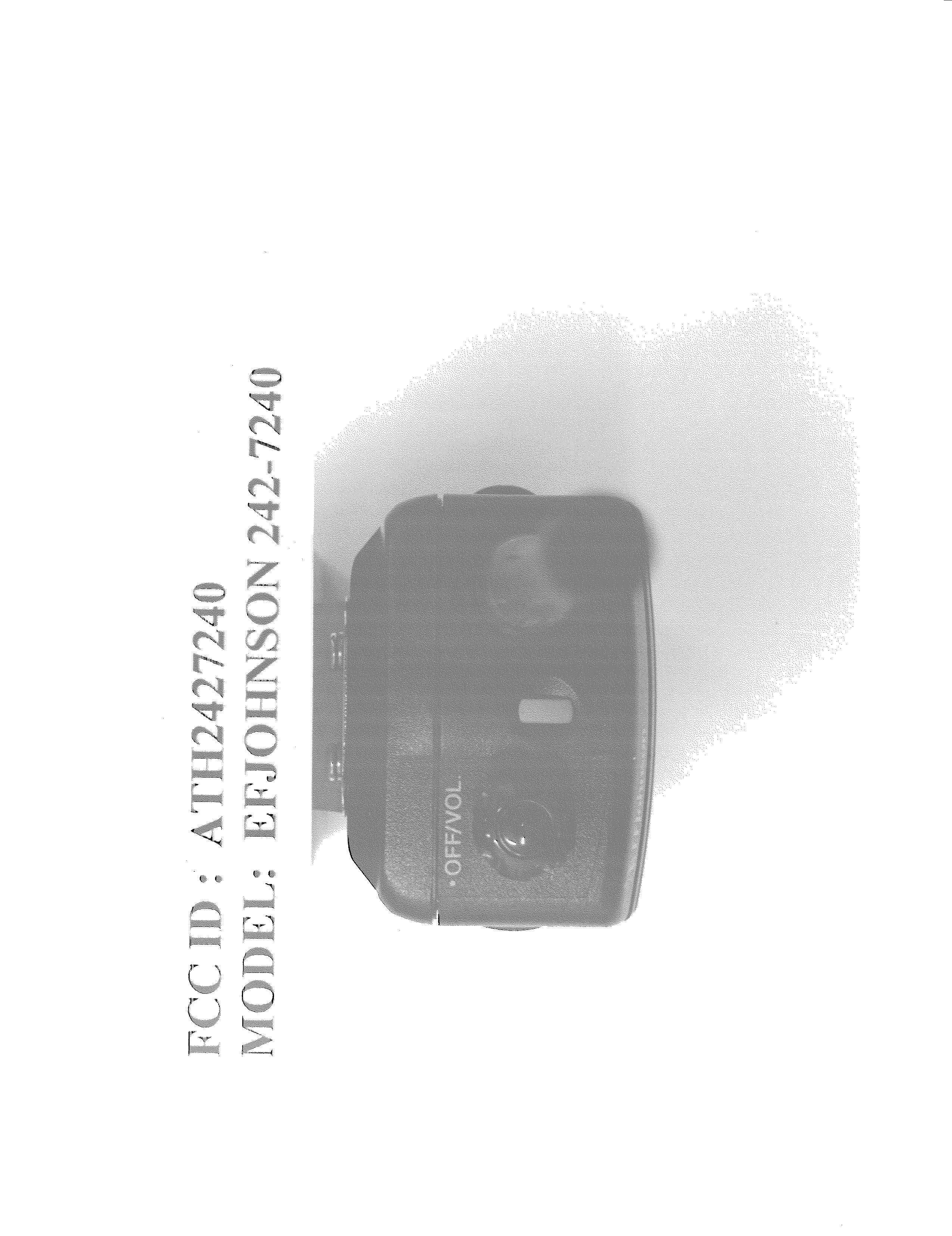
Click to zoom
Application Details
- Equipment Class
- TNB - Licensed Non-Broadcast Station Transmitter
- Date of Grant
- Apr 23, 2001
- Application Purpose
- Original Equipment
- Date of Application
- Oct 05, 2000
- Equipment Note
- UHF FM Handheld Transceiver Held-to-face
- Frequency Range
- 430.00000000 - 470.00000000
- Company
- E F Johnson Company
- Country
- United States
Documents & Files
Document Text
Text extracted from the exhibit documents filed with the FCC. Open a document above to read the original.
Users Manual
LTR-Net™ MANUAL 7200 Series Trunked Portable Radio OPERATING PRELIMINARY LAND MOBILE PRODUCT WARRANTY - The manufacturer’s warranty statement for this product is available from your product supplier or from EFJohnson, 299 Johnson Avenue, Box 1249, Waseca, MN 56093-0514. Phone (507) 835-6222. Copyright© 2000 by the E.F. Johnson Company The E.F. Johnson Company, which was founded in 1923, provides wireless communication systems solutions for public safety, government, and commercial customers. The company designs, manufactures, and markets conventional and trunked radio systems, mobile and portable subscriber radios, repeaters, and Project 25 digital radio products. E.F. Johnson is a wholly owned subsidiary of Transcrypt International, Inc. Viking Head/EFJohnson logo, LTR ® , LTR-Net ™ , and Call Guard ® are trademarks of the E.F. Johnson Company. All other company and/or product names used in this manual are trademarks and/or registered trademarks of their respective manufacturer. SAFETY INFORMATION 4 SAFETY INFORMATION The FCC has adopted a safety standard for human exposure to RF energy. Proper operation of this radio under normal conditions results in user exposure to RF energy below the Occupational Safety and Health Act and Federal Communication Commission limits. TO COMPLY WITH FCC R.F. EXPOSURE REQUIREMENTS Minimum Safe Distance: 2.5 cm (1.0 in) ANTENNA MOUNTING - Antenna as supplied by manufacturer must not be placed at a location such that any person or persons can come closer than the above-indicated mimimum safe distance to the antenna (2.5 cm). ANTENNA SUBSTITUTION - Do not substitute any antenna for the one supplied by manufacturer. You may be exposing person(s) to harmful radiation. Contact supplier or manufacturer for further instructions. WARNING Maintain separation distance from antenna of 2.5 cm (1.0 in) or more. DO NOT allow the antenna to touch or to come in very close prox- imity with the eyes, face, or any exposed body parts while the radio is transmitting. DO NOT operate the radio in explosive or flammable atmospheres. The transmitted radio energy could trigger blasting caps or cause an explosion. DO NOT operate the radio without the proper antenna installed. DO NOT allow children to operate or play with this transceiver. SAFETY INFORMATION 5 DO NOT dispose of the nickel metal-hydride battery pack used by this radio in fire because it can explode. Dispose of it in accordance with local regulations. Also, do not short the terminals because it may become very hot. NOTE: The above warning list is not intended to include all hazards that may be encountered when using this radio. This device complies with Part 15 of the FCC rules. Operation is subject to the condition that this device does not cause harmful inter- ference. In addition, changes or modifications to this equipment not expressly approved by the E.F. Johnson Company could void the user’s authority to operate this equipment (FCC rules, 47CFR Part 15.19). OTHER IMPORTANT OPERATING INFORMATION Usage in Blasting Areas - To avoid interference with blasting operations, be sure to turn the transceiver off in areas posted “Blasting Area” or “Turn Off Two-Way Radio”. Remote controlled RF devices are some- times used to set off explosives. Operation in Explosive Atmospheres - Turn the transceiver off when in an area with a potentially explosive atmosphere. Although rare, the trans- ceiver could generate a spark or a hot surface that could cause an explo- sion or fire resulting in bodily injury or even death. Operation in Flammable Atmospheres - Areas with potentially flam- mable atmospheres are usually, but not always, clearly posted. These areas may include fueling areas such as gas stations, fuel or chemical storage and transfer stations, below deck on boats, and areas where the air contains flammable chemicals or particles such as grain dust or metal powders. Do not use or transport the transceiver in any atmosphere or compartment potentially containing flammable gas, liquids, or explosives. TABLE OF CONTENTS 6 TABLE OF CONTENTS SAFETY INFORMATION . . . . . . . . . . . . . . . . . . . . . . . . . . . . . . . . . . 2 IMPORTANT OPERATING INFORMATION. . . . . . . . . . . . . . . . . . 4 QUICK REFERENCE GUIDE. . . . . . . . . . . . . . . . . . . . . . . . . . . . . . . 9 FEATURES . . . . . . . . . . . . . . . . . . . . . . . . . . . . . . . . . . . . . . . . . . . . . 10 General Features . . . . . . . . . . . . . . . . . . . . . . . . . . . . . . . . . . . . . . . . 10 LTR-Net Features . . . . . . . . . . . . . . . . . . . . . . . . . . . . . . . . . . . . . . . 10 LTR Features . . . . . . . . . . . . . . . . . . . . . . . . . . . . . . . . . . . . . . . . . . 10 Conventional Features . . . . . . . . . . . . . . . . . . . . . . . . . . . . . . . . . . . 10 CONTROLS AND DISPLAY. . . . . . . . . . . . . . . . . . . . . . . . . . . . . . . 11 Top Panel Controls . . . . . . . . . . . . . . . . . . . . . . . . . . . . . . . . . . . . . . 11 Side Controls . . . . . . . . . . . . . . . . . . . . . . . . . . . . . . . . . . . . . . . . . . 12 Display . . . . . . . . . . . . . . . . . . . . . . . . . . . . . . . . . . . . . . . . . . . . . . . 13 Front Panel Keys . . . . . . . . . . . . . . . . . . . . . . . . . . . . . . . . . . . . . . . 15 BASIC OPERATION . . . . . . . . . . . . . . . . . . . . . . . . . . . . . . . . . . . . . 20 Power-Up Sequence . . . . . . . . . . . . . . . . . . . . . . . . . . . . . . . . . . . . . 20 Backlight Operation . . . . . . . . . . . . . . . . . . . . . . . . . . . . . . . . . . . . . 20 Setting Volume Levels . . . . . . . . . . . . . . . . . . . . . . . . . . . . . . . . . . . 20 System/Group Display Mode . . . . . . . . . . . . . . . . . . . . . . . . . . . . . . 20 System and Group Select . . . . . . . . . . . . . . . . . . . . . . . . . . . . . . . . . 21 Keypad Disable . . . . . . . . . . . . . . . . . . . . . . . . . . . . . . . . . . . . . . . . 22 Transceiver Lock . . . . . . . . . . . …
Text truncated - open the document above for the full version.
Users Manual
LTR-Net™ MANUAL 7200 Series Trunked Portable Radio OPERATING PRELIMINARY LAND MOBILE PRODUCT WARRANTY - The manufacturer’s warranty statement for this product is available from your product supplier or from E.F. Johnson Company, 299 Johnson Avenue, Box 1249, Waseca, MN 56093-0514. Phone (507) 835-6222. Copyright© 2001 by the E.F. Johnson Company The E.F. Johnson Company, which was founded in 1923, provides wireless communication systems solutions for public safety, govern- ment, and commercial customers. The company designs, manufac- tures, and markets conventional and trunked radio systems, mobile and portable subscriber radios, repeaters, and Project 25 digital radio products. Viking Head/EFJohnson logo, LTR ® , LTR-Net ™ , and Call Guard ® are trademarks of the E.F. Johnson Company. All other company and/or product names used in this manual are trademarks and/or registered trademarks of their respective manufacturer. SAFETY TRAINING INFORMATION 4 SAFETY TRAINING INFORMATION WARNING This radio produces RF electromagnetic energy when transmitting and is designed and classified for “Occupational Use Only”. Radio equipment with this classification must be used only during the course of employ- ment by individuals aware of the hazards and the ways to minimize such hazards. This radio is NOT intended for use by the General Population in an uncontrolled environment. This radio has been tested and complies with FCC RF exposure limits for “Occupational Use Only”. In addition, it complies with the following standards and guidelines with regard to RF energy and electromagnetic energy levels and evaluation of such levels for exposure to humans: •FCC OET Bulletin 65 Edition 97-01 Supplement C, Evaluating Compliance with FCC Guidelines for Human Exposure to Radio Frequency Electromagnetic Fields. •American National Standards Institute (C95.1-1992), IEEE Standard for Safety Levels with Respect to Human Exposure to Radio Frequency Electromagnetic Fields, 3 kHz to 300 GHz. •American National Standards Institute (C95.3 -1992), IEEE Recom- mended Practice for the Measurement of Potentially Hazardous Electromagnetic Fields - RF and Microwave. CAUTION To ensure that your exposure to RF electromagnetic energy is within the FCC allowable limits for occupational use, always adhere to the following guidelines: •DO NOT operate the radio without the proper antenna attached. This may damage the radio and cause FCC RF exposure limits to be exceeded. The proper antenna is the antenna supplied with the radio by the manufacturer or an antenna specifically authorized by the manufacturer for use with this radio. SAFETY TRAINING INFORMATION 5 •DO NOT transmit more than 50% of total radio use time (50% duty cycle). Transmitting for more than 50% of the time can cause FCC RF exposure compliance requirements to be exceeded. This radio is transmitting whenever Tx is indicated in the lower right corner of the display. Pressing the PTT switch on the side usually causes the radio to transmit. •DO NOT use any accessories not specifically authorized by the E.F. Johnson Company for use with this radio such as batteries, speaker- microphones, belt clips, and antennas. The use of unauthorized accessories can cause FCC RF exposure compliance requirements to be exceeded. •ALWAYS keep the antenna at least 2.54 cm (1.0 inch) away from your body when transmitting to ensure FCC RF exposure compli- ance requirements are not exceeded. The best transmission quality results when the antenna is at least 5 cm (2 inches) away from your mouth and angled slightly to one side. NOTE: The preceding information is provided to make you aware of RF exposure and what to do to ensure that this radio is operated within FCC RF exposure limits. Electromagnetic Interference/Usage Compatibility This device complies with Part 15 of the FCC rules. Operation is subject to the condition that this device does not cause harmful interference. In addition, changes or modification to this equipment no expressly approved by the E.F. Johnson Company could void the user’s authority to operate this equipment (FCC Rules, 47CFR Part 15.19). DO NOT operate it in areas that are sensitive to RF energy such as aircraft, hospitals, blasting sites, and fuel storage sites. Areas with poten- tially flammable atmospheres are usually, but not always, clearly posted. These may include gas stations, fuel and chemical storage and transfer stations, below deck on boats, and areas where the air contains flammable chemicals or particles such as grain dust or metal powders. Dispose of the nickel metal-hydride battery used by this radio in accor- dance with local regulations.DO NOT dispose of it in fire because it can explode. Also, do not short the terminals because it may become very hot. TABLE OF CONTENTS 6 TABLE OF CONTENTS SAFETY TRAINING INFORMATION . . . . . . . . . . . . . . . . . . . . . . . . 4 QUICK REFERENCE GUIDE. . . . . . . . . . . . . . . . . . . . . . . . . . . . . . . 9 FEATURES . . . . . . . . . . . . . . . . . . . . . . . . . . . . . . . . . . . . . . . . . . . . . 10 General Features . . . . . . . . . . . . . . . . . . . . . . . . . . . . . . . . . . . . . . . . 10 LTR-Net Features . . . . . . . . . . . . . . . . . . . . . . . . . . . . . . . . . . . . . . . 10 LTR Features . . . . . . . . . . . . . . . . . . . . . . . . . . . . . . . . . . . . . . . . . . 10 Conventional Features . . . . . . . . . . . . . . . . . . . . . . . . . . . . . . . . . . . 10 CONTROLS AND DISPLAY. . . . . . . . . . . . . . . . . . . . . . . . . . . . . . . 11 Top Panel Controls . . . . . . . . . . . . . . . . . . . . . . . . . . . . . . . . . . . . . . 11 Side Controls . . . . . . . . . . . . . . . . . . . . . . . . . . . . . . . . . . . . . . . . . . 12 Display . . . . . . . . . . . . . . . . . . . . . . . . . . . . . . . . . . . . . . . . . . . . . . . 13 Front Panel Keys . . . . . . . . . . . . . . . . . . . . . . . . . . . . . . . . . . . . . . . 15 BASIC OPERATION . . . . . . . . . . . . …
Text truncated - open the document above for the full version.
Users Manual
LTR-Net™ MANUAL 7200 Series Trunked Portable Radio OPERATING PRELIMINARY LAND MOBILE PRODUCT WARRANTY - The manufacturer’s warranty statement for this product is available from your product supplier or from E.F. Johnson Company, 299 Johnson Avenue, Box 1249, Waseca, MN 56093-0514. Phone (507) 835-6222. Copyright© 2001 by the E.F. Johnson Company The E.F. Johnson Company, which was founded in 1923, provides wireless communication systems solutions for public safety, govern- ment, and commercial customers. The company designs, manufac- tures, and markets conventional and trunked radio systems, mobile and portable subscriber radios, repeaters, and Project 25 digital radio products. Viking Head/EFJohnson logo, LTR ® , LTR-Net ™ , and Call Guard ® are trademarks of the E.F. Johnson Company. All other company and/or product names used in this manual are trademarks and/or registered trademarks of their respective manufacturer. SAFETY TRAINING INFORMATION 4 SAFETY TRAINING INFORMATION WARNING This radio produces RF electromagnetic energy when transmitting and is designed and classified for “Occupational Use Only”. Radio equipment with this classification must be used only during the course of employ- ment by individuals aware of the hazards and the ways to minimize such hazards. This radio is NOT intended for use by the General Population in an uncontrolled environment. This radio has been tested and complies with FCC RF exposure limits for “Occupational Use Only”. In addition, it complies with the following standards and guidelines with regard to RF energy and electromagnetic energy levels and evaluation of such levels for exposure to humans: •FCC OET Bulletin 65 Edition 97-01 Supplement C, Evaluating Compliance with FCC Guidelines for Human Exposure to Radio Frequency Electromagnetic Fields. •American National Standards Institute (C95.1-1992), IEEE Standard for Safety Levels with Respect to Human Exposure to Radio Frequency Electromagnetic Fields, 3 kHz to 300 GHz. •American National Standards Institute (C95.3 -1992), IEEE Recom- mended Practice for the Measurement of Potentially Hazardous Electromagnetic Fields - RF and Microwave. CAUTION To ensure that your exposure to RF electromagnetic energy is within the FCC allowable limits for occupational use, always adhere to the following guidelines: •DO NOT operate the radio without the proper antenna attached. This may damage the radio and cause FCC RF exposure limits to be exceeded. The proper antenna is the antenna supplied with the radio by the manufacturer or an antenna specifically authorized by the manufacturer for use with this radio. SAFETY TRAINING INFORMATION 5 •DO NOT transmit more than 50% of total radio use time (50% duty cycle). Transmitting for more than 50% of the time can cause FCC RF exposure compliance requirements to be exceeded. This radio is transmitting when- ever Tx is indicated in the lower right corner of the display. Pressing the PTT switch on the side usually causes the radio to transmit. •DO NOT use any accessories not specifically authorized by the E.F. Johnson Company for use with this radio such as batteries, speaker-micro- phones, belt clips, and antennas. The use of unauthorized accessories can cause FCC RF exposure compliance requirements to be exceeded. •ALWAYS keep the antenna and radio at least 2.54 cm (1.0 inch) away from your body when transmitting to ensure FCC RF exposure compliance requirements are not exceeded. The best transmission quality results when the antenna is at least 5 cm (2 inches) away from your mouth and angled slightly to one side. •This unit has not been tested for FCC RF exposure compliance in applica- tions where the unit is transmitting while body worn on the belt clip. This product is not intended for use in applications where transmissions are required while the unit is body worn with the use of the belt clip. NOTE: The preceding information is provided to make you aware of RF expo- sure and what to do to ensure that this radio is operated within FCC RF expo- sure limits. Electromagnetic Interference/Usage Compatibility This device complies with Part 15 of the FCC rules. Operation is subject to the condition that this device does not cause harmful interference. In addition, changes or modification to this equipment no expressly approved by the E.F. Johnson Company could void the user’s authority to operate this equipment (FCC Rules, 47CFR Part 15.19). DO NOT operate it in areas that are sensitive to RF energy such as aircraft, hospitals, blasting sites, and fuel storage sites. Areas with potentially flammable atmospheres are usually, but not always, clearly posted. These may include gas stations, fuel and chemical storage and transfer stations, below deck on boats, and areas where the air contains flammable chemicals or particles such as grain dust or metal powders. Dispose of the nickel metal-hydride battery used by this radio in accordance with local regulations. DO NOT dispose of it in fire because it can explode. Also, do not short the terminals because it may become very hot. TABLE OF CONTENTS 6 TABLE OF CONTENTS SAFETY TRAINING INFORMATION . . . . . . . . . . . . . . . . . . . . . . . . 4 QUICK REFERENCE GUIDE. . . . . . . . . . . . . . . . . . . . . . . . . . . . . . . 9 FEATURES . . . . . . . . . . . . . . . . . . . . . . . . . . . . . . . . . . . . . . . . . . . . . 10 General Features . . . . . . . . . . . . . . . . . . . . . . . . . . . . . . . . . . . . . . . . 10 LTR-Net Features . . . . . . . . . . . . . . . . . . . . . . . . . . . . . . . . . . . . . . . 10 LTR Features . . . . . . . . . . . . . . . . . . . . . . . . . . . . . . . . . . . . . . . . . . 10 Conventional Features . . . . . . . . . . . . . . . . . . . . . . . . . . . . . . . . . . . 10 CONTROLS AND DISPLAY. . . . . . . . . . . . . . . . . . . . . . . . . . . . . . . 11 Top Panel Controls . . . . . . . . . . . . . . . . . . . . . . . . . . . . . . . . . . . . . . 11 Side Controls . . . . . . . . . . . . . . …
Text truncated - open the document above for the full version.
Users Manual
OPERATION 2-2 January 2001 Part No. 001-7240-001 Figure 2-2 Display BUSY M G S UID Tx P2 C L O System Scan List Phone Group Group Scan List Scan Call 8-Character Alphanumeric MonitorEncryption Keypad Dial Mode Low Power Option Select Priority Transmitter Keyed Lock UID/Aux Group Low Battery Not Used Conv Ch Busy Display 2.2 CONTROLS AND DISPLAY 2.2.1 TOP PANEL CONTROLS NOTE: The top panel controls are shown in Figure 2-1. On-Off Volume - Turning this knob clockwise turns power on and sets the volume level. Turning it coun- terclockwise to the detent turns power off. Power is on when information appears in the display. Refer to Section 2.3.3 for more information on setting volume. Option Switch 1 - This switch can be programmed to control a specific function (see Section 2.5.1). Antenna Jack - Connection point for the antenna. Accessory Connector - When the protective cover is removed, this connector can be used to access PTT, speaker, and microphone lines for transceiver service testing. It is also the connection point for the computer when programming the transceiver. Battery Release Button (Not shown) - This button is located on the bottom end of the transceiver, and it is pressed to release the battery so that it can slide down- ward and be removed from the radio. NOTE: Turn off transceiver power before removing the battery. This ensures that current settings are prop- erly saved and the de-registration message is sent. 2.2.2 SIDE CONTROLS Option Switch 2 - This switch can be programmed to control a specific function (see Section 2.5.1). PTT (Push-To-Talk) - This switch keys the transmitter so that a message can be transmitted. The “ Tx” icon is displayed when the transmitter is keyed. Option Switch 3 - This switch can be programmed to control a specific function (see Section 2.5.1). 2.2.3 DISPLAY 8-Character Alphanumeric Display - This area of the display indicates the selected system and group (Section 2.3.4), the dialed number (Section 2.7), error conditions, and other information (Section 2.12.4). - Indicates that the displayed system is in the scan list and scanned normally (see Section 2.6.7). - The base portion of this icon is displayed when the displayed group is programmed for telephone calls, and the top portion (receiver) is displayed when the dial mode is selected (see Section 2.7). S Option Switch 2 PTT Switch Option Switch 3
Block Diagram
1 CIRCUIT DESCRIPTION Figure 1 Synthesizer and Transmitter Block Diagram GENERAL The 7240 Portable is a compact two-way radio consisting of an RF board, Logic/Audio board, and Keypad/ Display board. The RF board is shielded by a metal case. The radio is powered by a 7.5V NiMH battery pack and has a side connector that permits external access to many radio control functions and electrical connections. The 4-watt transmitter operates in the 430-470 MHz range. It is modulated with microphone audio, subaudible signaling and squelch control signals, and in-band audio tones. To generate the fundamental transmitter frequency, the exciter incorporates phase lock technology to control the stability of the internal voltage controlled oscillator (VCO) with a very stable reference signal provided by an internal temperature compensated crystal controlled oscillator (TCXO). The synthesizer produces an output signal at the assigned transmitter frequency. A voltage-controlled oscillator (VCO) operating at the fundamental transmitter frequency produces this signal. A phase locked loop (PLL) controls and stabilizes the VCO frequency and locks it to the frequency of a high stability signal derived from a TCXO with 1.5 PPM stability that is located on the RF board. To suppress frequency pulling during transmission, the exciter isolates the frequency determining circuit from the rest of the transmitter chain with RF buffer amplifiers. If the synthesizer becomes unlocked, it sends a signal to the control logic on the Logic/ Audio board which turns off the transmitter to prevent interference with other channels. A removable 3 dB gain antenna is mounted on the top of the radio for RF power transmission. The circuit description which follows includes TCXO, VCO, Synthesizer/PLL, Exciter, RF Amplifier and Power Control sections. Charge Pump U201 12.800 MHz TCXO Reference Divider Main Divider Prescaler Control Div by 64/65 Prescaler Phase Detector Synthesizer IC U202 fR fV U203 U203 DC-DC Converter Lock Detect Loop Filter C214- C217 Receive VCO (385-425 MHz) Transmit VCO (430-470 MHz) Q501/ Q502 Q531/ Q532 Buffer Buffers Q503 Q533/ Q534 VCO Assembly Power Amplifier Module U101 Antenna Switch Directional Coupler Forward Power S101 D101, D102 Antenna Tx Freq VCO Freq Q101 Amplifier Power Control U102A/B, U103 TRANSMITTER SYNTHESIZER Low-Pass Filter L107, L108, L110 Tx Audio/Data From Logic/Audio Bd Tx Mod Balance Q535 First Injection To Receiver Rx RF To Receiver Power Control From Logic/Audio Board To Logic/ Audio Bd
Cover Letter(s)
E.F. Johnson Company, 299 Johnson Ave., P.O. Box 1249, Waseca, MN 56093-0514 Phone: (507) 835-6222 Fax: (507) 835-8356 RADIO COMMUNICATIONS PRODUCTS & SYSTEMS Operations Center March 6, 2001 Federal Communications Commission Via Electronic Filing Attention:Joe Dichoso Applicant:E.F. Johnson Co. Equipment:FCC ID: ATH2427240 EA98978 Reference:Correspondence 18182 Dear Mr. Dichoso: This is in reply to your referenced correspondence. Item 1. The portable product being tested is being marketed in applications where speaker/microphone operation is not required. To that extent, E.F. Johnson will not offer a speaker/microphone accessory for this product. Also, because of the rather unique arrangement of the accessory connector, there would not be an after market supplier of such an option. The accessory connector is intended for use in transceiver programming and factory and field testing. The service manual has been modified to exclude any reference of the use of this connector for anything other than programming and testing. A copy of the page in the service manual describing the use of the accessory connector is attached. In addition, all references in the service manual related to body worn accessories have been removed. In addition, the safety training section of the operator’s manual has been changed to add a section stating that this portable has not been tested for body worn applications with the belt clip, nor is intended for use with body worn accessories. A copy of the revised operator’s manual is attached. Item 2. The requested change to the safety training section of the operator’s manual has been done. The revised manual is attached. We trust that these answers are satisfactory. Sincerely, John Oblak Chief Engineer, E.F. Johnson Co.
Cover Letter(s)
E.F. Johnson Company, 299 Johnson Ave., P.O. Box 1249, Waseca, MN 56093-0514 Phone: (507) 835-6222 Fax: (507) 835-8356 RADIO COMMUNICATIONS PRODUCTS & SYSTEMS Operations Center April 16, 2001 Federal Communications Commission Via Electronic Filing Attention:Joe Dichoso Applicant:E.F. Johnson Co. Equipment:FCC ID: ATH2427240 EA98978 Reference:Correspondence 18650 Dear Mr. Dichoso: This is in reply to your referenced correspondence. Item 1. The uniqueness of the connector stems from the fact that it is mechanically different from others that are used in other similar products. In other words, there is not an after market supplier for headsets that mate with this product. This is not to say that a supplier could not tool a mating connector to work. However, it is not expected that, in the intended market for this product, a speaker microphone would be required, nor production of an after market product would be economically justified. We believe that the operator’s manual cautionary statement that the product is not intended for use in applications where body worn transmission is required is sufficient to train the user in proper operation. Item 2. In our previous reply letter, I stated that the accessory connector was provided for transceiver programming and field and factory testing. The programming of the transceiver is described in section 3.1 of the service manual (previously supplied). In this application, a computer is connected through a Remote Programming Interface (RPI) box to the radio through the connector in question. Radio parameters are downloaded to the radio through this connection. The factory and field testing of the radio uses the same type of connection as above. In this mode, the radio may be tuned via the computer. A microphone input and speaker output are provided for inputs and outputs for tuning and radio performance testing. At the present, this mode of tuning and testing is only available to the factory. We trust that these answers are satisfactory. Sincerely, John Oblak Chief Engineer, E.F. Johnson Co.
ID Label/Location Info
Devise must be restricted to occupational use to satisfy FCC RF exposure compliance. See owner’s manual for specific operating requirements. CAUTION !
Operational Description
1 CIRCUIT DESCRIPTION Figure 1 Synthesizer and Transmitter Block Diagram GENERAL The 7240 Portable is a compact two-way radio consisting of an RF board, Logic/Audio board, and Keypad/ Display board. The RF board is shielded by a metal case. The radio is powered by a 7.5V NiMH battery pack and has a side connector that permits external access to many radio control functions and electrical connections. The 4-watt transmitter operates in the 430-470 MHz range. It is modulated with microphone audio, subaudible signaling and squelch control signals, and in-band audio tones. To generate the fundamental transmitter frequency, the exciter incorporates phase lock technology to control the stability of the internal voltage controlled oscillator (VCO) with a very stable reference signal provided by an internal temperature compensated crystal controlled oscillator (TCXO). The synthesizer produces an output signal at the assigned transmitter frequency. A voltage-controlled oscillator (VCO) operating at the fundamental transmitter frequency produces this signal. A phase locked loop (PLL) controls and stabilizes the VCO frequency and locks it to the frequency of a high stability signal derived from a TCXO with 1.5 PPM stability that is located on the RF board. To suppress frequency pulling during transmission, the exciter isolates the frequency determining circuit from the rest of the transmitter chain with RF buffer amplifiers. If the synthesizer becomes unlocked, it sends a signal to the control logic on the Logic/ Audio board which turns off the transmitter to prevent interference with other channels. A removable 3 dB gain antenna is mounted on the top of the radio for RF power transmission. The circuit description which follows includes TCXO, VCO, Synthesizer/PLL, Exciter, RF Amplifier and Power Control sections. Charge Pump U201 12.800 MHz TCXO Reference Divider Main Divider Prescaler Control Div by 64/65 Prescaler Phase Detector Synthesizer IC U202 fR fV U203 U203 DC-DC Converter Lock Detect Loop Filter C214- C217 Receive VCO (385-425 MHz) Transmit VCO (430-470 MHz) Q501/ Q502 Q531/ Q532 Buffer Buffers Q503 Q533/ Q534 VCO Assembly Power Amplifier Module U101 Antenna Switch Directional Coupler Forward Power S101 D101, D102 Antenna Tx Freq VCO Freq Q101 Amplifier Power Control U102A/B, U103 TRANSMITTER SYNTHESIZER Low-Pass Filter L107, L108, L110 Tx Audio/Data From Logic/Audio Bd Tx Mod Balance Q535 First Injection To Receiver Rx RF To Receiver Power Control From Logic/Audio Board To Logic/ Audio Bd 2 SYNTHESIZER DESCRIPTION NOTE: A synthesizer block diagram is located in Figure 1. INTRODUCTION The synthesizer output signal is produced separate receive and transmit VCOs on the RF board. The frequency of these VCOs is controlled by a DC voltage produced by the phase detector in synthesizer chip U202. The phase detector senses the phase and frequency of the two input signals. One signal is the reference frequency from TCXO U201, and the other is from the VCO. If these signals are not the same frequency, the phase detector changes the VCO control voltage which …
Text truncated - open the document above for the full version.
Contact Information
Applicant
Karthik Rangarajan(SR VP Engineering)
Technical Contact
M. Flom Associates, IncMorton Flom
[email protected]480 926 3100
3356 N. San Marcos Pl., Suite 107 · Chandler, Arizona · United States
Non-Technical Contact
M. Flom Associates, Inc.Morton Flom
[email protected]480 926 3100
Test Firm
M. Flom Associates, Inc.Morton Flom
Technical Specifications
| # | Rule Parts | Frequency Range | Power Output | Emission | Tolerance |
|---|---|---|---|---|---|
| 2 | 9 | 430 MHz - 470 MHz | 4 W | 16K0F3E | 1.5 ppm |
Other Applications from E F Johnson Company
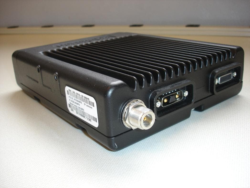
ATH2425M80
Nov 19, 2015DUAL BAND VHF AND 700/800 MHz MOBILE TRANSCEIVER
Equipment Class
TNB - Licensed Non-Broadcast Station Transmitter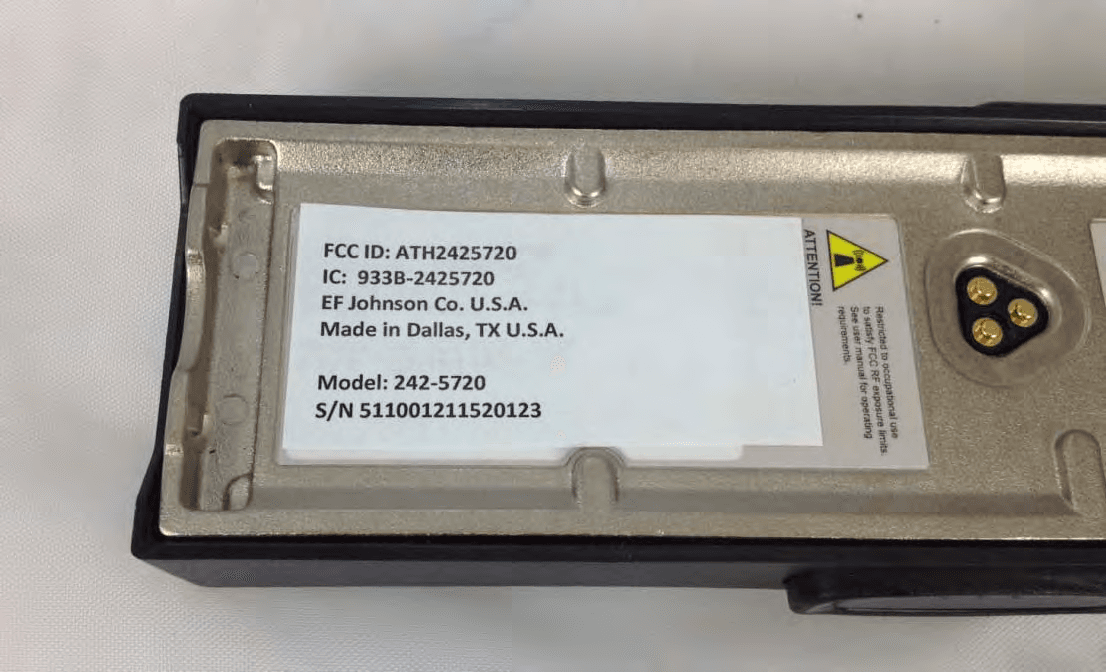
ATH2425720
Sep 30, 2012VP 600 UHF Land Mobile Radio Transceiver
Equipment Class
TNF - Licensed Non-Broadcast Transmitter Held to Face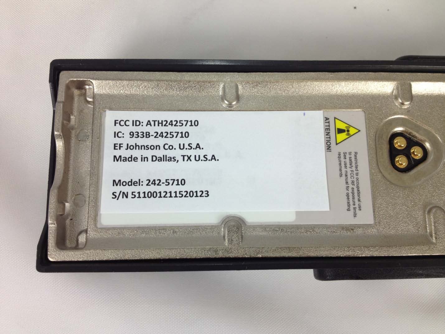
ATH2425710
Sep 16, 2012Portable VHF Push-To-Talk (PTT) Radio Transceiver
Equipment Class
TNF - Licensed Non-Broadcast Transmitter Held to Face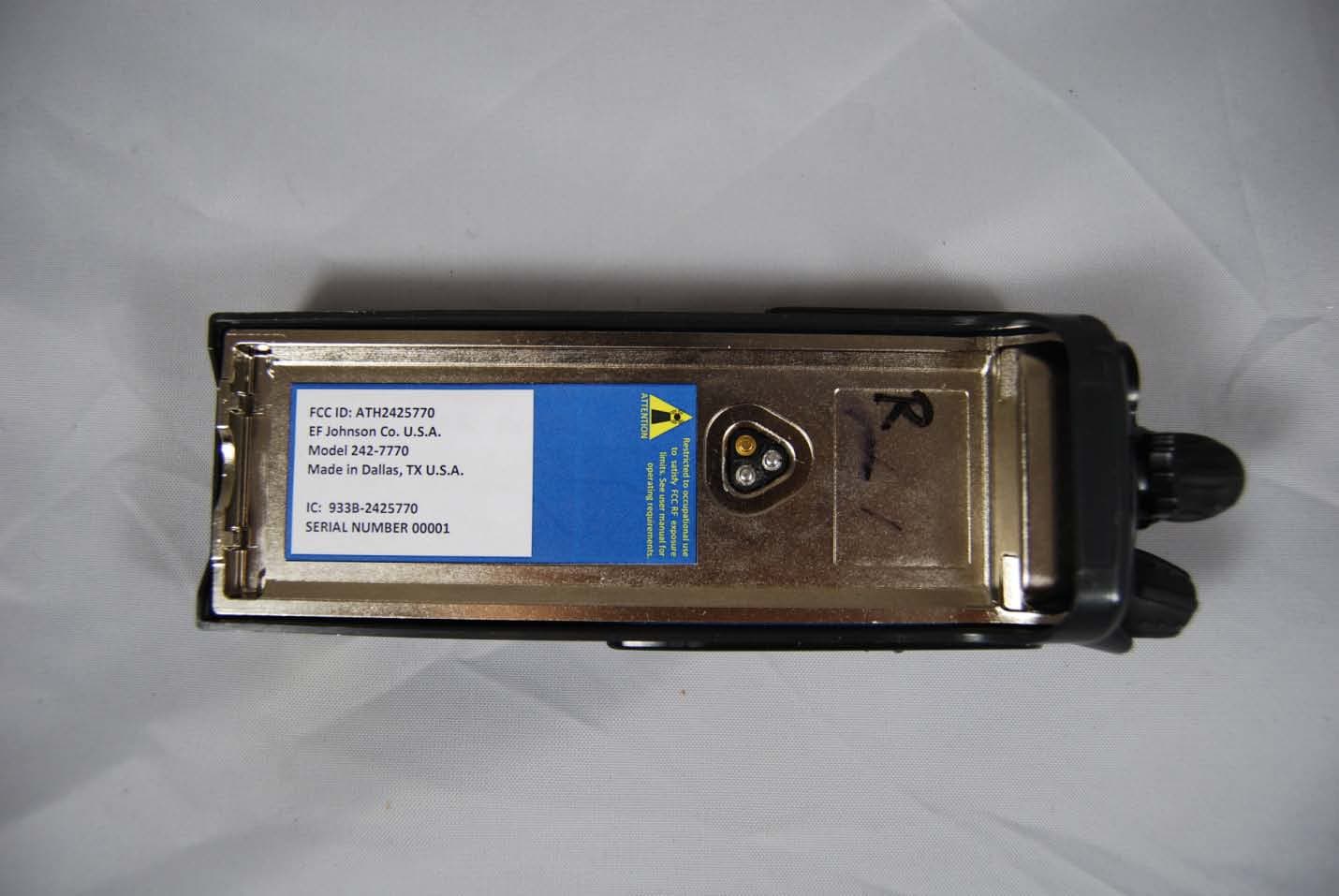
ATH2425770
Feb 09, 2012Vantage 700/800 MHz Portable Radio
Equipment Class
TNF - Licensed Non-Broadcast Transmitter Held to Face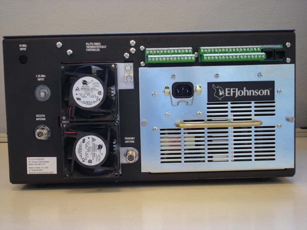
ATH2422607
Mar 07, 2010700 MHz LAND MOBILE REPEATER
Equipment Class
TNB - Licensed Non-Broadcast Station Transmitter