AWANB-250Bluetooth Wireless Speaker
NYNE MULTIMEDIA INC.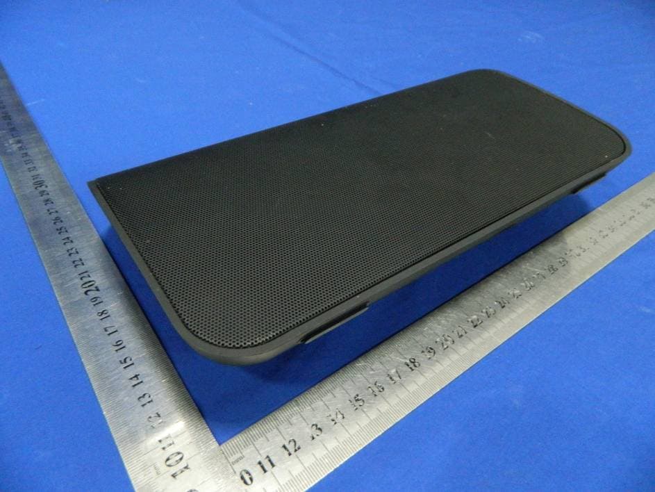
Click to zoom
Application Details
- Equipment Class
- DSS - Part 15 Spread Spectrum Transmitter
- Date of Grant
- Oct 08, 2012
- Application Purpose
- Original Equipment
- Date of Application
- Oct 08, 2012
- Equipment Note
- Bluetooth Wireless Speaker
- Frequency Range
- 2402.00000000 - 2480.00000000
- Company
- NYNE MULTIMEDIA INC.
- Country
- United States
Documents & Files
Document Text
Text extracted from the exhibit documents filed with the FCC. Open a document above to read the original.
Users Manual
NB-250 nyne.com User Manual ......................... 3 Manual del usuario ........... 17 Manuel utilisateur .............. 31 FR ES EN Série Haut parleur Bluetooth FR Altavoz serie Bluetooth ES Bluetooth Speaker Series EN 3 English EN Contents 1 Important 4 Safety 4 Notice 5 2 Introduction 7 What is Bluetooth technology 7 Introduction to NB-250 7 Overview 8 3 Preparation 9 Unpack 9 Place the device 9 Connect power 9 Turn on the device 9 Pair with a Bluetooth-enabled device 10 4 Operation 11 Play music from a Bluetooth connected device 11 Listen from an auxiliary device 11 Charge a portable device through the USB socket 12 5 Specifications 13 6 Frequently asked questions (FAQ) 14 4EN 1 Important Safety The lightning fl ash with arrowhead symbol within an equilateral triangle is intended to alert the user to the presence of un-isolated, dangerous voltage within the inside of the device that may be of suffi cient magnitude to constitute a risk of electric shock to persons. The exclamation point within an equilateral triangle is intended to alert the user to the presence of important operating and servicing instructions in the literature accompanying the device. Read these instructions before operation. Keep these instructions for future reference. Follow all instructions for installation, use and maintenance of the device. To avoid tilt or drop, place the device on a fl at and hard surface. To clean the device, disconnect power fi rst. Clean only with soft and dry cloth. To ensure compatibility, only use accessories recommended by the manufacturer. When the device is suddenly moved from cold to warm surroundings, condensation may form in the housing of the device. Before use, leave the device in the warm environment until the moisture evaporates. Keep the device away from heat sources, such as a radiator, heater, oven, amplifi er, naked fl ames or direct sunlight. Never block any ventilation openings. • Do not expose the device to sand or dust, or cover it with items, such as newspapers, table cloths, or curtains. • Do not operate the device in an enclosed cabinet. Leave suffi cient free space around the device for adequate ventilation. Keep the device away from moisture. Never expose the device to rain, dripping or splashing. If water penetrates into the device, unplug the power cord and contact your dealer. Continuous use in this case may result in fi re or electric shock. Make sure that the power supply voltage is within the range indicated on the label on the device or power adapter. If you are not sure of the type of power supply, consult your dealer or local power company. Do not defeat the safety purpose of the polarized or grounding-type plug. A polarized plug has two blades with one wider than the other. A grounding type plug has two blades and a third grounding prong. The wide blade or the third prong is provided for your safety. If the provided plug does not fi t into your outlet, consult an electrician for replacement of the obsolete outlet. When connected to a power outlet, power is always fl owing into the 5 English EN device. To completely disconnect power, unplug the power cord. When you unplug the power cord, always hold the plug instead of the cord. Do not overload power strips and extension cords. Overloading can result in fi re or electric shock. The wall socket should be located near the device and be easily accessible. Where the mains plug or an appliance coupler is used as the disconnect device, the disconnect device shall remain readily operable. During lightning storms or when the device is not to be used for a long period of time, always unplug the power cord of the device. Pulling on the power cord can damage the wires inside the cord and may cause fi re or electric shock. Do not attempt to repair or service the device yourself. Opening or removing the cabinet may expose you to electric shock, and other hazards. If repair is required, contact your dealer and refer all servicing to qualifi ed service personnel. Do not use the device if any abnormality occurs. If any smoke or odor becomes apparent, unplug the power cord and contact your dealer immediately. Do not try to repair the device yourself. Avoid using dropped or damaged appliances. If the device is dropped and the housing is damaged, the internal components may not function normally. Unplug the power cord immediately and contact your dealer for repair. Continued use of the device may cause fi re or electric shock. Before moving the device, make sure to disconnect the power cord and any other cables fi rst. To reduce the risk of electric shock, do not touch any connector with wet hands. Never remove the housing of the device. Never lubricate any part of the device. Never place the device on top of any other electrical equipment. Notice Modification Any modifi cation (such as removing the speaker grill) to the device, without prior authorization from the manufacturer, may void your warranty and authority to operate the device. FCC compliance statement This equipment has been tested and found to comply with the limits for a Class B digital device, pursuant to part 15 of the FCC Rules. These limits are designed to provide reasonable protection against harmful interference in a residential installation. This equipment generates, uses, and can radiate radio frequency energy and, if not installed and used in accordance with the instruction manual, may cause harmful interference to radio communications. However, there is no guarantee that interference will not occur in a particular installation. If this equipment does cause harmful interference to radio or television reception, which 6EN can be determined by turning the equipment off and on, the user is encouraged to try to correct the interference by one or more of the following measures: • Relocate the receiving antenna. • Increase the separation between the equipment and receiver. • Connect the equipment into an outlet on a circuit different from that to which t…
Text truncated - open the document above for the full version.
Cover Letter(s)
Confidentiality Request Letter Confidentiality Request Letter Confidentiality Request Letter NYNE MULTIMEDIA INC. (2012-09-16) To: Federal Communications Commission Authorization and Evaluation Division Confidentiality Request regarding application for certification of FCC ID: AWANB-250 We hereby request confidential treatment of information accompanying this application as outlined below: - Block diagram - Operation description - Schematic The applicant understands that pursuant to Section 0.457 and 0.459 of the Rules, disclosure of this application and all accompanying documentation will not be made before the date of the Grant for this application. The above materials contain trade secrets and proprietary information not customarily released to the public. The public disclosure of these materials may be harmful to the applicant and provide unjustified benefits to its competitors. E-mail: [email protected] Phone: 650 483 6373 Fax: 805 988 0791 Address 3451 Lunar Court Oxnard, California, 93030 USA
ID Label/Location Info
Label Location Proposed Label Location on EUT
Internal Photos
BT Module Antenna
Test Report
SHENZHEN EMTEK CO., LTD. REPORT NO: ES120712117E FCC ID: AWANB-250 DATE: 08/20/2012 Page 1 of 52 ELECTROMAGNETIC EMISSIONS COMPLIANCE REPORT INTENTIONAL RADIATOR CERTIFICATION TO FCC PART 15 SUBPARTC REQUIREMENT OF Bluetooth Wireless Speaker MODEL No.: NB-250 Trade Mark : FCC ID: AWANB-250 REPORT NO: ES120712117E ISSUE DATE: August 20, 2012 Prepared for NYNE MULTIMEDIA, INC 13451 Lunar Court Oxnard, Ca 93030 Prepared by SHENZHEN EMTEK CO., LTD Bldg 69, Majialong Industry Zone, Nanshan District, Shenzhen, Guangdong, China TEL: 86-755-26954280 FAX: 86-755-26954282 SHENZHEN EMTEK CO., LTD. REPORT NO: ES120712117E FCC ID: AWANB-250 DATE: 08/20/2012 Page 3 of 52 Ta b l e o f C o n t e n t s 1. GENERAL INFORMATION ................................................................................................. 5 1.1 PRODUCT DESCRIPTION........................................................................................................................... 5 1.2 RELATED SUBMITTAL(S) / GRANT (S) ..................................................................................................... 5 1.3 TEST METHODOLOGY.............................................................................................................................. 5 1.4 SPECIAL ACCESSORIES............................................................................................................................ 5 1.5 EQUIPMENT MODIFICATIONS.................................................................................................................. 5 1.6 TEST FACILITY........................................................................................................................................ 6 2. SYSTEM TEST CONFIGURATION .................................................................................... 7 2.1 EUT CONFIGURATION............................................................................................................................. 7 2.2 EUT EXERCISE........................................................................................................................................ 7 2.3 TEST PROCEDURE.................................................................................................................................... 7 2.4 LIMITATION............................................................................................................................................. 7 2.5 CONFIGURATION OF TESTED SYSTEM................................................................................................... 11 2.6 EQUIPMENT USED IN TESTED SYSTEM....................................................................................................... 11 2.7 DESCRIPTION OF TEST MODES.................................................................................................................... 12 3. SUMMARY OF TEST RESULTS ....................................................................................... 13 4. CONDUCTED EMISSIONS TEST ..................................................................................... 14 4.1 MEASUREMENT PROCEDURE:................................................................................................................ 14 4.2 TEST SET-UP (BLOCK DIAGRAM OF CONFIGURATION) ....................................................................... 14 4.3 MEASUREMENT EQUIPMENT USED: ...................................................................................................... 14 4.4 CONDUCTED EMISSION LIMIT.................................................................................................................... 14 4.5 MEASUREMENT RESULT:....................................................................................................................... 15 4.6 CONDUCTED MEASUREMENT PHOTOS: ...................................................................................................... 16 5. RADIATED EMISSION TEST ............................................................................................ 17 5.1 MEASUREMENT PROCEDURE................................................................................................................. 17 5.2 TEST SET-UP (BLOCK DIAGRAM OF CONFIGURATION) ....................................................................... 18 5.3 MEASUREMENT EQUIPMENT USED: ...................................................................................................... 19 5.4 MEASUREMENT RESULT........................................................................................................................ 20 5.5 RADIATED MEASUREMENT PHOTOS: ......................................................................................................... 24 6. CHANNEL SEPARATION TEST ....................................................................................... 26 6.1 MEASUREMENT PROCEDURE................................................................................................................. 26 6.2 TEST SET-UP (BLOCK DIAGRAM OF CONFIGURATION) ....................................................................... 26 6.3 MEASUREMENT EQUIPMENT USED: ...................................................................................................... 26 6.4 MEASUREMENT RESULTS:..................................................................................................................... 26 7. BANDWIDTH TEST ............................................................................................................. 33 7.1 MEASUREMENT PROCEDURE................................................................................................................. 33 7.2 TEST SET-UP (BLOCK DIAGRAM OF CONFIGURATION) ....................................................................... 33 SHENZHEN EMTEK CO., LTD. REPORT NO: ES120712117E FCC ID: AWANB-250 DATE: 08/20/2012 Page 4 of 52 7.3 MEASUREMENT EQUIPMENT USED: ......................................................…
Text truncated - open the document above for the full version.
Test Setup Photos
Radiated Measurement Photos: Conducted Measurement Photos:
Contact Information
Applicant
Hootan Rouhani(Product Development Director)
Test Firm
EMTEK (Shenzhen) Co., Ltd.David Lee
Technical Specifications
| # | Rule Parts | Frequency Range | Power Output |
|---|---|---|---|
| 1 | 15C | 2.40 GHz - 2.48 GHz | 1.78 mW |
Other Applications from NYNE MULTIMEDIA INC.
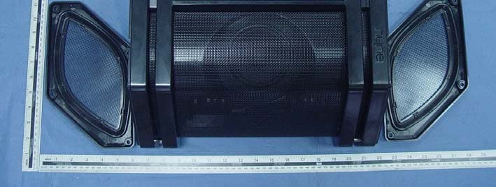
AWA-NYNEREBEL
Dec 14, 2015NYNE REBEL
Equipment Class
DXX - Part 15 Low Power Communication Device Transmitter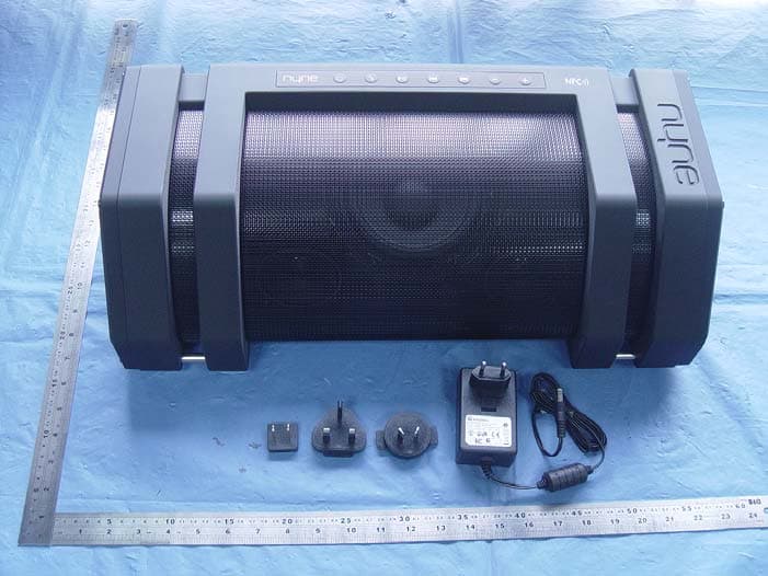
AWA-NYNEROCK
Nov 30, 2015NYNE ROCK
Equipment Class
DTS - Digital Transmission System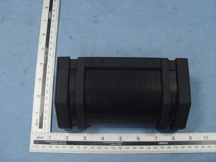
AWA-NYNEEDGE
Apr 29, 2015Bluetooth speaker
Equipment Class
DSS - Part 15 Spread Spectrum Transmitter
AWA-ADS15
Apr 23, 2015Speaker Box
Equipment Class
DSS - Part 15 Spread Spectrum Transmitter
AWANYNE-AQUA
Jun 30, 2014Selfy Shutter Remote
Equipment Class
DSS - Part 15 Spread Spectrum Transmitter