AZ489FT3794Hand-held Portable Radio
Motorola Solutions, Inc.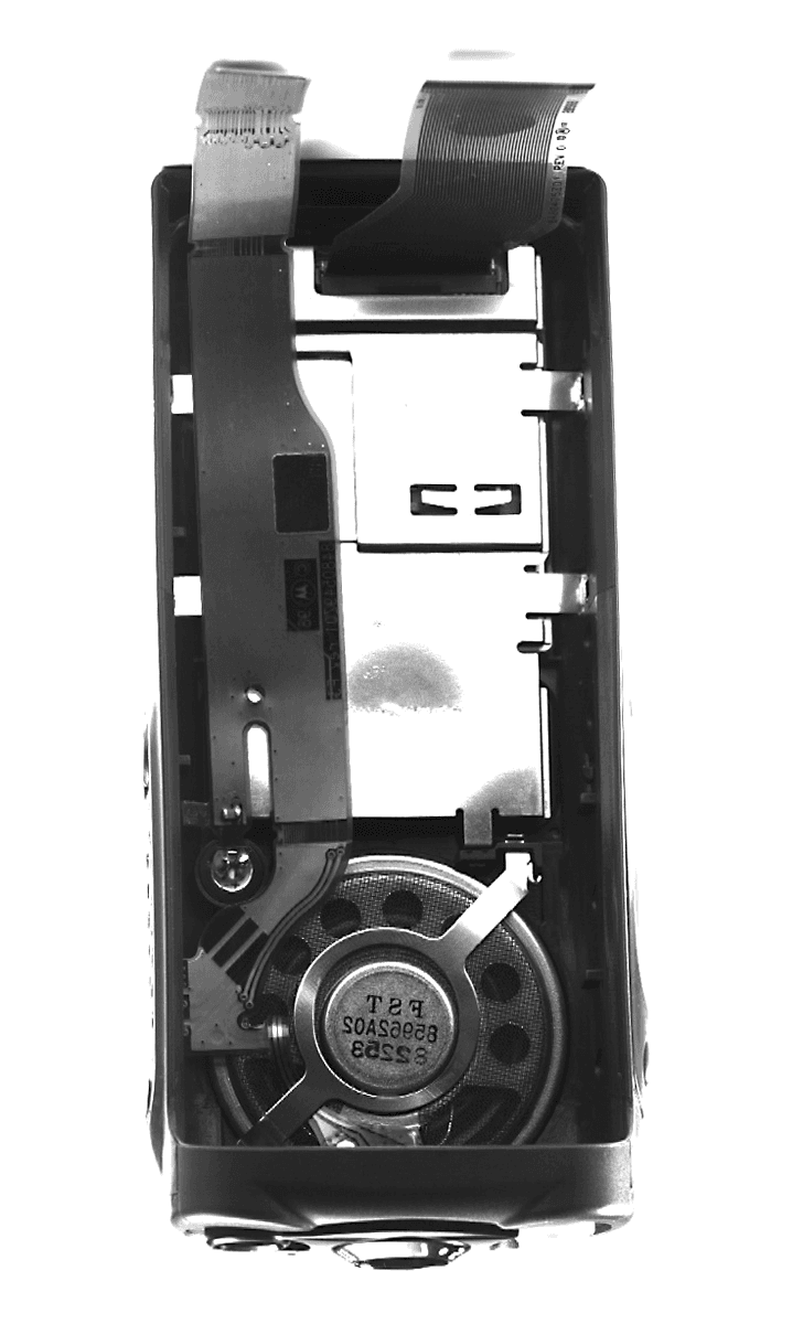
Click to zoom
Application Details
- Equipment Class
- TNF - Licensed Non-Broadcast Transmitter Held to Face
- Date of Grant
- Sep 07, 1998
- Application Purpose
- Original Equipment
- Date of Application
- Jul 01, 1998
- Equipment Note
- Hand-held Portable Radio
- Frequency Range
- 136.00000000 - 174.00000000
- Company
- Motorola Solutions, Inc.
- Country
- United States
Documents & Files
Document Text
Text extracted from the exhibit documents filed with the FCC. Open a document above to read the original.
Users Manual
GP338 Professional Two-Way Radio Motorola Inc. FCC ID: AZ489FT3794 EXHIBIT 12 Specifications 4A-1-3 4A-1.1Specifications GENERAL TRANSMITTER RECEIVER All specifications are subject to change without notice. VHF Frequency: 136-174 MHz Channel Capacity: Popular : 16 Channels Preferred : 128 Channels Power Supply: 7.5 Volts ±20% Dimensions with Standard Capacity NiMH Battery: with High Capacity NiMH Battery: 153mm x 62.3mm x 44mm 153mm x 62.3mm x 46mm Weight: with Standard Capac- ity NiMH Battery: with High Capacity NiMH Battery: 431.3 g 464.8 g Average Battery Life @ (5-5-90 Duty Cycle) Standard Capacity NiMH Battery: High Capacity NiMH Battery: Low Power High Power Sealing: Passes rain testing per IP54 Shock: Meets MIL-STD-810-C,D & E and TIA/EIA 603 Vibration: Meets MIL-STD-810-C,D & E and TIA/EIA 603 Dust: Meets MIL-STD-810-C,D & E and IP54 Humidity: Meets MIL-STD-810-C,D & E and TIA/EIA 603 FCC ID AZ489FT3794 VHF RF Output NiMH @ 7.5V: Low 1W High 5W Frequency: 136-174 MHz Channel Spacing: 12.5/20/25 kHz Freq. Stability (-30°C to +60°C) 0.00025% Spurs/Harmonics: -36 dBm Audio Response: (from 6 dB/oct. Pre- Emphasis, 300 to 3000Hz) +1, -3 dB Audio Distortion: @ 1000 Hz, 60% Rated Max. Dev. <5% FM Noise: -40 dB FCC ID:AZ489FT3794 Emission Designator 16K0F3E, 11K0F3E VHF 12.5kHz VHF 20/ 25kHz Frequency: 136-174MHz 136-174MHz Sensitivity 12dB EIA SINAD: 0.35 μV 0.35 μV Adjacent Channel Selectivity ETS -60 dB -70 dB Intermodulation ETS -65 dB -65 dB Freq. Stability (-30°C to +60°C): 5ppm 5ppm Spur Rejection: -70 dB -70 dB Image Rejection: -70 dB -70 dB Audio Output @ <5% Distortion 500 mW 500 mW English 2-YEAR LIMITED WARRANTY FOR RADIOS We thank you for purchasing our Motorola radios. These radios are manufactured according to the highest quality standards set and are backed by Motorola’s two (2) year warranty. The rechargeable Motorola supplied batteries have a one (1) year warranty. Kindly approach your dealer for more information. Motorola warrants its radios and batteries against defects in material and workmanship under normal use and service for the period stated above. Motorola recommends that you use Motorola supplied accessories and batteries in connection with the radio. We would also advise you against attempting any modifications or repairs or any other form of unauthorised service to your radio. Should you have any queries, please contact: Singapore - Telephone/Fax: (65) 3810408&9/2871068 Beijing- Telephone/Fax: (86-10) 68437222/68438195 Please see next page for more information. Fill in the details of your radio below for your own reference: Model Name/No.: Serial Number: Date of Purchase: Dealer Name: Address: Telephone: #WarisPreUser.book Page 1 27, May 1998, 9:44 AM 1 Contents English CONTENTS CONTENTS Radio Overview . . . . . . . . . . . . . . . . . . . . 3 Parts of the Radio. . . . . . . . . . . . . . . . . . . . . . . . 3 On/Off/Volume Knob . . . . . . . . . . . . . . . . . 4Channel Selector Knob. . . . . . . . . . . . . . . . . 4Programmable Buttons . . . . . . . . . . . . . . . . . 4Push-to-Talk (PTT) Button . . . . . . . . . . . . . 7Microphone . . . . . . . . . . . . . . . . . . . . . . . . . 7Menu Keys . . . . . . . . . . . . . . . . . . . . . . . . . . 7Keypad Keys (for keypad radios only) . . . . 8 LCD Screen . . . . . . . . . . . . . . . . . . . . . . . . . . . . 9 Programmable Buttons Audio Indicators . . 11 Getting Started . . . . . . . . . . . . . . . . . . . . 13 Battery Information . . . . . . . . . . . . . . . . . . . . . 13 Battery Status . . . . . . . . . . . . . . . . . . . . . . . 13Charging your Battery . . . . . . . . . . . . . . . . 13 Accessory Information. . . . . . . . . . . . . . . . . . . 14 Attaching the Battery . . . . . . . . . . . . . . . . . 14Removing the Battery . . . . . . . . . . . . . . . . 14Attaching the Antenna . . . . . . . . . . . . . . . . 15Removing the Antenna. . . . . . . . . . . . . . . . 15Attaching the Belt Clip. . . . . . . . . . . . . . . . 15Removing the Belt Clip . . . . . . . . . . . . . . . 16 Turning the Radio On or Off . . . . . . . . . . . . . . 16Adjusting the Radio’s Volume . . . . . . . . . . . . . 16Selecting a Radio Channel . . . . . . . . . . . . . . . . 17Sending a Call. . . . . . . . . . . . . . . . . . . . . . . . . . 17Receiving a Call . . . . . . . . . . . . . . . . . . . . . . . . 17 Radio Calls . . . . . . . . . . . . . . . . . . . . . . . .19 Selective Call . . . . . . . . . . . . . . . . . . . . . . . . . . 19 Making a Selective Call . . . . . . . . . . . . . . . 19Receiving a Selective Call . . . . . . . . . . . . . 19 Call Alert . . . . . . . . . . . . . . . . . . . . . . . . . . . . . 20Radio Check . . . . . . . . . . . . . . . . . . . . . . . . . . . 21Emergency Alarm. . . . . . . . . . . . . . . . . . . . . . . 22Radio Call List . . . . . . . . . . . . . . . . . . . . . . . . . 22 Editing an Entry (for keypad radios only) . 22 Select Zone . . . . . . . . . . . . . . . . . . . . . . . . . . . . 23Talkaround . . . . . . . . . . . . . . . . . . . . . . . . . . . . 23Squelch . . . . . . . . . . . . . . . . . . . . . . . . . . . . . . . 24Power Level . . . . . . . . . . . . . . . . . . . . . . . . . . . 25Tone Tagging . . . . . . . . . . . . . . . . . . . . . . . . . . 25 Name Tone Tagging . . . . . . . . . . . . . . . . . . 25Call Tone Tagging . . . . . . . . . . . . . . . . . . . 26 Scan . . . . . . . . . . . . . . . . . . . . . . . . . . . . .27 Starting or Stopping a Scan Operation . . . . . . . 27 Using the Menu. . . . . . . . . . . . . . . . . . . . . . 27 #WarisPreUser.book Page 1 27, May 1998, 9:44 AM Contents 2 English CONTENTS Using the Scan key . . . . . . . . . . . . . . . . . . . 28 Talkback. . . . . . . . . . . . . . . . . . . . . . . . . . . . . . 28Deleting a Nuisance Channel. . . . . . . . . . . . . . 28Adding a Deleted Nuisance Channel back to the Scan List . . . . . . . . . . . . . . . . . . . . . . . . . . . . . 28Scan Channel Discovery Alert. . . . . . . . . . . . . 28Editing th…
Text truncated - open the document above for the full version.
Attestation Statements
MOTOROLA INC FCC ID: AZ489FT3794 STATEMENT OF CERTIFICATION The technical data supplied with this application, having been taken under my supervision is hereby duly certified. The following is a statement of my qualifications: 1) Dipl. Ing. FH Wiesbaden (Bachelor of Science) Dipl. WI.FH Mainz(MBA) 2) 19 years experience in the development, testing and certification of Land Mobile Communications Products NAME: Karlheinz Kraft SIGNATURE: DATE:29. May 1998 POSITION: Compliance Commissioner I hereby certify that the above application was prepared under my direction and that to the best of my knowledge and belief, the facts set forth in the application and accompanying technical data are true and correct: NAME: Rüdiger Maurer SIGNATURE: DATE: 29 May 1998 POSITION: Director Engineering HW EXHIBIT 1 MOTOROLA INC FCC ID: AZ489FT3794
Cover Letter(s)
FCC ID:AZ489FT3794 ______________________________________________________________________________ Radio Products Group 8000 West Sunrise Boulevard, Fort Lauderdale, Florida 33322. (954) 723-5000 Date: July 02, 1998 Authorization & Evaluation Division Federal Communications Commission Laboratory 7435 Oakland Mills Road Columbia, MD 21046 Subject: Application for Type Acceptance of Transmitter with FCC ID: AZ489FT3794. Attention: George Tannahill, Frank Coperich Gentlemen: Motorola Inc, 8000 West Sunrise Boulevard, Fort Lauderdale, Florida, herein submits application for Type Acceptance of the subject transmitter. This transmitter is primarily intended for use in a portable radio application with capabilities for communications with transmit power of 1 - 5 Watts or 30 dBm to 37 dBm. The power is variable 20 % of the value listed. The subject transmitter complies with Section 90.203 of the rules in that the operator cannot directly program transmit frequencies using only the unit's normally accessible external controls. Enclosed is a complete Type Acceptance Application. Contact me (954) 723-5793 if you require any additional information. Sincerely, Mike Ramnath FCC Liaison Fax (954) 723-4794
External Photos
FCC ID: AZ489FT3794 PHOTOGRAPHS The following photographs are attached. 10—1. Front view of preferred model with keypad and display with antenna 10—2. Front view of plain minus model without antenna 10—2. Front view of popular nonkeypad model 10—2. Front view of popular keypad model 10—2. Front view of preferred nonkeypad model 10—2. Front view of preferred keypad model 10—3. Back view of radio with battery removed showing FCC label location 10—4. Back view of the front housing showing keypad board installed 10—5. Front view of keypad board and display 10—5. Back view of keypad board and display 10—6. Transceiver board and chassis 10—7. Top of transceiver board with shields 10—8. Top of transceiver board without shields 10—9. Back of transceiver board with shields 10-10. Back of transceiver board without shields EXHIBIT 10 FCC ID: AZ489FT3794 Front view of preferred model with keypad and display with antenna 10--1 FCC ID: AZ489FT3794 Front view of Plain MinusFront view of PopularFront view of Popular Model w/o antennaModel w/o antennaKeypad Model w/o antenna Front view of PreferredFront view of Preferred Full Model w/o antennaModel w/o antenna10--2 FCC ID: AZ489FT3794 Back view of radio with battery removed showing FCC label location 10--3 FCC ID: AZ489FT3794 Back view of the front housing showing keypad board installed 10--4 FCC ID: AZ489FT3794 Front view of keypad board Back view of keypad board and displayand display 10--5 FCC ID: AZ489FT3794 Transceiver Board and Chassis 10--6 FCC ID: AZ489FT3794 Top of Transceiver Board with Shields 10-7 FCC ID: AZ489FT3794 Top of Transceiver Board without Shields 10--8 FCC ID: AZ489FT3794 Back of Transceiver Board with Shields 10--9 FCC ID: AZ489FT3794 Back of Transceiver Board without Shields 10--10
ID Label/Location Info
MOTOROLA INC FCC ID: AZ489FT3794 IDENTIFICATION LABEL LOCATION See The Attached Photograph Or Sketch X Back Of Radio Back Of Radio Under Belt Clip TYPE X The label is a paper polyester film laminate with a pressure sensitive adhesive backing. The adhesive is a permanent type acrylic with a minimum peel strength of 40 oz/inch. MARKINGS (TEXT) X See The Attached Photograph Label Attached Below. See Attached Drawing. EXHIBIT 2
ID Label/Location Info
MOTOROLA INC FCC ID: AZ489FT3794 GENERAL INFORMATION 1. PRODUCTION PLANS: Volume production of this device is planned. 2. APPLICATION REFERENCES: a. Portable Products and their application. b. Portable Products Transmitter Modulation Methods c. Motorola, Taunusstein Open Area Test Site. 3. DATA SUBMITTAL PROCEDURE: Data is supplied in accordance with Part 2, subpart J of the Commissions’ Rules. 4. SIMILIAR APPLICATIONS: Type Acceptance application with FCC ID:AZ489FT4826.
Operational Description
MOTOROLA INC FCC ID: AZ489FT3794 DESCRIPTION I.Transmitter Technical Characteristics -- Pursuant 2.983 (d) A. RF Power Output1 - 5 Watt (Variable) B. Frequency Range 136 - 174 MHz C. Frequency Stability 0.00025 % D. Emissions 16K0F3E, 11K0F3E E. Spurious Emissions - 50dBc F. DC Voltage and Current into 7.5 Volts the final RF amplifier stage/stages 1,55Amps II.Transmitter Application : This transmitter is primarily intended for use as a handheld portable radio. The transmitter is characterised by the following features, options and accessories. A. Power Supply Available Attached battery B. Antenna Available 1. Helical X , Telescopic , Whip , Dipole , Dribble External , External _ . C. Squelch Types Available 1. Carrier Squelch X . 2. Tone "Private Line" X . 3. Digital "Private Line" X . D. Microphone - Control 1. Internal Microphone X . 2. Remote Shoulder Mounted Microphone X . E. Maximum Transmit Channel Capability 128 . F. Housing The transmitter will be housed in the housing shown in the accompanying photographs. G. Other Options 1. Single Tone Encoder X 2. Multiple Single Tone Encoder X 3. Touch Code Encoder X 4. Unit ID Encoder X 5. EMS Telemetry Encoder 6. Time out Timer X 7. Voice Encryption X 8. Digital Signaling 9. Sel-Call Decode 10. Trunking X 11. Conventional X 12. Digital Voice EXHIBIT 4
Parts List/Tune Up Info
MOTOROLA INC FCC ID: AZ489FT3794 Function of RF Semiconductors & Other Active Devices SchematicDeviceCircuit Key Type Application Source CR3301Schottky Ring Quad DiodeMixerHewlett Packard CR3303DiodeLimiterMotorola CR503Dual LEDOperator InterfaceStanley D3270Varactor DiodeOscillator Tuning 2nd LOToshiba D3301Varactor DiodeBandpass Filter TuningSiemens D3302Varactor DiodeBandpass Filter TuningSiemens D3521Pin DiodeRX/TX SwitchingMacom D3551Pin DiodeRX/TX SwitchingMacom D3701DiodeVoltage MultiplierROHM D3702DiodeVoltage MultiplierROHM D3761Varactor DiodeOscillator TuningSony D3821Varactor DiodeOscillator TuningToshiba D3831Varactor DiodeOscillator TuningToshiba D3832Varactor DiodeOscillator TuningToshiba Q3200BJTIF AmplifierMotorola Q3201BJTAGCMotorola Q3270BJT2nd IF OscillatorPhillips Q3301BJTAGCMotorola Q3302BJTPreamplifierMotorola Q3501MOSFETRF Final AmplifierMotorola Q3561BJTDC SwitchingMotorola Q3721Dual BJTDC SwitchingROHM Q3801BJTLO BufferMotorola Q400MOSFETDC SwitchingPhillips Q403BJTDC SwitchingMotorola Q405Dual BJTDC SwitchingROHM Q410Dual BJTDC SwitchingROHM Q416MOSFETDC SwitchingPhillips Q502DUAL BJTLED DriverROHM Q505BJTDC SwitchingMotorola U3201IC3.3V Regulator VDDAAnalog Devices U3220ICReceiver backend ICMotorola U3501ICRF Driver AmplifierMotorola U3502ICRF Power Control ICMotorola U3503ICTemperature SensorNational Semiconductor U3701ICFrequency Synthesizer ICAtmel U3711ICVoltage Regulator 5VAnalog Devices U3801ICVCO Buffer ICPhillips U400ICVoltage Regulator VDDDNational Semiconductor U404ICAudio ProcessingATMEL U405ICStatic RAMMitsubishi U406ICFlash ROMATMEL U407ICEEPROMATMEL U409ICMicroprocessorMotorola U410ICVoltage RegulatorImpala Linear U420ICAudio Power AmplifierPhillips Y3200Crystal FilterIF FilterMotorola Y3761Crystal OscillatorReference OscillatorMotorola ____________________________________________________________________________ COMMENTS: The Motorola designators are special code numbers for active devices used in Motorola radios. These devices are either identical or derived from the device family listed under MOTOROLA INC FCC ID: AZ489FT3794 Source, by the manufacturer or are proprietary to Motorola. Service people do not have access to any cross-references or given any information on proprietary devices and are prevented from making unauthorised substitution. EXHIBIT 5
Parts List/Tune Up Info
MOTOROLA INC FCC ID: AZ489FT3794 TUNEUP PROCEDURE 8.0TUNING PROCEDURES This procedure was written in the sequence the radio is to be tuned. The following points should be noted: 1) Radio controller refers to the microprocessor in the radio. 2) Tester/test controller refers to external test system (hardware as well as software). 3) Values in tables may change to improve yield. 8.1.1PROGRAMMING I.C.S WITH DEFAULT DATA a) Power up radio. b) Program DAC for receive per table 9.2 c) Program the Fractional N for receive per table 9.6 - using the appropriate Band Select setting per table 9.9 - using the appropriate Rx. Frequency information. 8.1.2Synthesizer Reference freq setting: Set the internal synthesizer reference frequency selection to: TX RX Note: $01 selects 2.1Mhz, $10: 2.225MHz, $11:2.4MHz, $00 selects internal algorithm UHF $00 $00 VHF $00 $00 LB 800 $00 $00 8.1.3 REFERENCE OSCILLATOR AND TEMPERATURE COMPENSATION Reference oscillator frequency is 16.8Mhz unless stated otherwise in the table below: a) Read crystal data from the crystal body and enter into computer. ( A complete procedure on temperature compensation will be described later .) EXHIBIT 7 MOTOROLA INC FCC ID: AZ489FT3794 8.1.4 RATED AUDIO: a) Set radio to Carrier Squelch Test Environment and frequencies, LB VHF= F4 (154.925MHz) UHF = 438.05Mhz 800 = 860.525 MHz b) Inject a -47dBm RF signal modulated with a 1kHz tone at the 60% of rated deviation. c) Adjust the ASFIC Volume Attenuator (VOL7 - VOL0) to obtain 500mW of audio power into a speaker or equivalent resistive load, V=3.16V. d) Store the tuned Rated Volume Attenuator setting in the codeplug. NOTE 1: Maximum Volume = Rated Volume + Max Audio Overdrive (in normal operation mode) Max Audio Overdrive = 12.0dB 8.1.5 RECEIVER SQUELCH TUNING: ( Note that squelch adjustment can only be done after front end tuning is completed) The squelch softpots must be tuned for every channel spacing until production data shows otherwise a) Determine the frequency band of operation of the radio ( Low band, VHF, UHF, 800MHz etc...) b) Determine the radio channel spacing. That is 12.5KHz, 20KHz or 25KHz. c) Set radio channel spacing to 25KHz d) Set the radio to operate at frequency F1 (F5 for 800 MHz). e) Modulate the signal generator with 1KHz tone @ 60% of rated system deviation. See table 1 f) Set the RF level to -47dbm and then adjust the audio output for 50% rated audio. g) Set the ASFICcmp squelch attenuator (SQPOT5-0) to $0, to fully unsquelch the radio. h) Adjust the signal gen. RF level until 10db sinad is obtained (CCITT filter set to OFF). i) Increase the squelch attenuator settings (SQPOT5-0) until the speaker audio output is muted. j) Wait 500msec, monitoring for squelch chatter. If chatter is present, repeat step h. k) Repeat steps e to j for frequencies F2 to F7 (F6 to F7 for 800 MHz) that require tuning. Values for the untuned frequencies are to be interpolated by the test controller. l).Repeat step d to step k for the rest of the channel spacing. m) Program the squelch attenuator settings into the radio codeplug (Note: the radio application software adds a negative offset values to the squelch attenuators when the radio unsquelch. This effectively adds a hysteresis to the squelch performance thus improving squelch chattering.) Squelch tuning frequency recommended for PAT tuning UHF Band1UHF Band2UHF 300MhzVHF800 MHz Test/Tune Freq403-470 F1402.975 136.225 F2413.025 142.225 F3425.025 148.225 F4437.025 154.625 F5449.025 161.225850.975 MOTOROLA INC FCC ID: AZ489FT3794 F6460.025 167.225860.525 F7470.025 173.625870.025 8.1.6 FRONT END BANDPASS FILTER TUNING: The FE for LB and 800 MHz need not be tuned. Note that the Dac for VHF/UHF is the DAC from the ASFIC a) Set radio to Carrier Squelch Test Environment. b) Program ASFIC to route the RSSI output to Universal connector c) The radio has 7 test points for Front End Bandpass filter, program the synthesizer to receive at the following test/tune frequencies Frequency Bands (MHz) Used in PAT UHF Band1UHF Band2UHF 300MHzVHF Test/Tune Freq403-470 F1402.975 136.225 F2413.025 142.225 F3425.025 148.225 F4437.025 154.625 F5449.025 161.225 F6460.025 167.225 F7470.025 173.625 DAC Start values for front end tuning. Test/Tune Freq UHF BAND 2UHF BAND 1UHF 300MHzVHF F1not tuned offset used F2not tuned offset used F357 decimal F4not tuned offset used F5not tuned offset used F6not tuned offset used F7not tuned offset used d) Inject a -70 dBm RF signal with Frequency F1 (F3 for vhf)with no modulation. e) Measure the RSSI voltage with a high impedance DC voltmeter capable of 1mV resolution.. It is recommended that a RC (1.5K-47uF) be added at the input of the voltmeter to reduce RSSI noise. f) PreSet the DAC value in the Front End Filter Softport with the DAC start values. g) Measure the RSSI voltage. Increment (vhf, decrement for uhf) the DAC value twice (VHF) and compare to the previous value h) Repeat until the change between the two latest RSSI reading is lower than the target value. UHF : 0.42%VHF : 0.5% i) Store the Front End Filter Softport in the codeplug For F1. (not for vhf) j) Repeat for other test point frequencies (F2-F7) that require tuning (not for VHF) For MOTOROLA INC FCC ID: AZ489FT3794 VHF calculate the offset from DAC value to the default value of F3 and add the offset to all softpot values. Note: if any calculation exceeds the minimum or maximum softpot value set the softpot to the minimum or maximum value. Band owners should define the minimum value to prevent varicap problems. 8.1.7 RSSI slope selection bit settings: These settings sets the RSSI slope selection in the ZIF at power up: 20-25KHz Channel spacings LBVHFUHF800 Bit 24Bit 25Bit 26Bit 24Bit 25Bit 26Bit 24Bit 25Bit 26Bit 24Bit 25Bit 26 111111000 12.5KHz Channel spacings: LBVHFUHF800 Bit 24Bit 25Bit 26Bit 24Bit 25Bit 26Bit 24Bit 25Bit 26Bit 24Bit 25Bit 26 111111000 8.1.8 RSSI display tuning for RSSI level1 to RSSI level 6 There are 6 RSSI display bars for models that …
Text truncated - open the document above for the full version.
Schematics
MOTOROLA INC FCC ID: AZ489FT3794 SCHEMATIC DIAGRAMS The following schematic diagrams will be similar to those that appear in the final service manual. RF-Transmitter section C3535 5185963A15 1 Microstrip LM50C 27pF 15pF 120pF C3536 C3523 18pFC3524 TAB3 4 TAB4 3300pF C3568 J3502 ANTENNA_NUT 1 TAB1 2 TAB2 3 1 2 3 SHIELD SH3501 SHIELD 1 RX_IN 5V 1 2 TP3502 UNSWB+ SHIELD SH3502 SHIELD Q3561 D G S DATA Q3501 330K 220pFC3564 R3564 0.1 R3519 R3547 RX_IN_1_PA 12K CSX RESET C3546 330pF 330pFC3509 C3506 .022uF 68nH 7.66nH L3504 L3513 47pF C3512 VHF PA 100 R3544 UNSW_LPLUS_3_PA 0102726B11 DACVAR1_1_PA UNSWB_LPLUS_2_PA D3551 RESET_1_PA 33pF 330pF C3503 C3501 300 R3503 R3501 18 300 R3502 16 RFIN 11 G2 6 RFOUT1RFOUT2 7 1 VCNTRL NC3 10 NC4 15 GND1 4 GND2 5 GND3 12 GND4 13 2 VG1 3 VG2 U3501 NC1 8 NC2 9 5V_2_PA UNSWB+ 09Z67 16 V45 15 VG 6 VL 19 VLIM 17 VSH DATA_2_PA 23 RX 32 T1 2 T2 30 TEMP V1 20 14 V10 V2 18 V3 24 GND1 8 GND2 25 4 INT OVI 31 11 Q QX 10 1 RF 21 RS CI 3 5 CJ 7 CL 26 CLK 12 CQ CQX 13 28 DATA 9 F168 09Z46 U3502 22 ANO BPOS 2729 CEX BEAD L3519 BEAD CLK_2_PA CSX_2_PA CLK UNSWB+ UNSWB+ R3562 C35507.5pF 68K 100 11.03nH R3545 L3512 C3534 4.7pF C3533 7.5pF R3546 33K C3532 68pF 330pF R3512 C3518 220 .022uF C3504 1uHL3523 C3526 C3525 .022uF L3503 10pF 68nH 5.6K R3561 .01uFC3565 3300pF 3300pF C3562 C3563 R3563 470K C3561 .022uF C3527 1.5pF L3521 7.66nH C3514 470pF C3515 220pF 3300pF C3521 C3569 .022uF 7.5K R3571 R3569 R3572120120R3573120 7.66nH 56pF L3552 C3551 C3552 39 68pF R3551 R3570 100pF 10K C3516 1uF C3517 L355143.67nH L3532 43.67nH 43.67nH L3531 23.75nH L3522 C3505 330pF R3505 5.6pF 470 C3539 1uF C3519 22pF C3560 30.54nH L3518 39nH L3538 L351513.85nH 18nH L3511 C3544 R3542 330pF 5.6K C3547.022uF R3541NU6.8K R3543 100 C3531 18pFC3537 20pF HEATSINK 1 3 H3501 RF_JACK J3501 GND 4 12 .022uFC3543 330pF C3541 C3542 30pF .022uF C3513 C3502 33pF TX_INJ 5.6nH L3501 GND 3 POS VOUT 2 DACVAR1 U3503 D3521 TX_INJ_1_PA NC_U3502_11NC_U3502_12NC_U3502_13NC_U3502_10NC_U3502_9 C3528 9.1pF 15k R3548 330pFC3507 C3506.022uF 68nHL3502 VD1 14 NU WARIS PORTABLE VHF 8408062B05_T1RF-SECTION TRANSMITTER13.May 1998 Rudi Kachel CRK002 TAU ZWG0130021P ZWG0130021P EXHIBIT 6
Schematics
4A-3-10: Motorola Inc C3535 5185963A15 1 Microstrip LM50C 27pF 15pF 120pF C3536 C3523 18pF C3524 TAB3 4 TAB4 3300pF C3568 J3502 ANTENNA_NUT 1 TAB1 2 TAB2 3 123 SHIELD SH3501 SHIELD 1 RX_IN 5V 12 TP3502 UNSWB+ SHIELD SH3502 SHIELD Q3561 D G S DATA Q3501 330K 220pF C3564 R3564 0.1 R3519 R3547 RX_IN_1_PA 12K CSX RESET C3546 330pF 330pF C3509 C3506 .022uF 68nH 7.66nH L3504 L3513 47pF C3512 VHF PA 100 R3544 UNSW_LPLUS_3_PA 0102726B11 DACVAR1_1_PA UNSWB_LPLUS_2_PA D3551 RESET_1_PA 33pF 330pF C3503 C3501 300 R3503R3501 18 300 R3502 16 RFIN 11 G2 6 RFOUT1 RFOUT2 7 1 VCNTRL NC3 10 NC4 15 GND1 4 GND2 5 GND3 12 GND4 13 2 VG1 3 VG2 U3501 NC1 8 NC2 9 5V_2_PA UNSWB+ 09Z67 16 V45 15 VG 6 VL 19 VLIM 17 VSH DATA_2_PA 23 RX 32 T1 2 T2 30 TEMP V1 20 14 V10 V2 18 V3 24 GND1 8 GND2 25 4 INT OVI 31 11 Q QX 10 1 RF 21 RS CI 35 CJ 7 CL 26 CLK 12 CQ CQX 13 28 DATA 9 F168 09Z46 U3502 22 ANO BPOS 27 29 CEX BEAD L3519 BEAD CLK_2_PA CSX_2_PA CLK UNSWB+ UNSWB+ R3562 C3550 7.5pF 68K 100 11.03nH R3545 L3512 C3534 4.7pF C3533 7.5pF R3546 33K C3532 68pF 330pF R3512 C3518 220 .022uF C3504 1uH L3523 C3526 C3525 .022uF L3503 10pF 68nH 5.6K R3561 .01uF C3565 3300pF 3300pF C3562 C3563 R3563 470K C3561 .022uF C3527 1.5pF L3521 7.66nH C3514 470pF C3515 220pF 3300pF C3521 C3569 .022uF 7.5K R3571 R3569 R3572 120 120 R3573 120 7.66nH 56pF L3552 C3551 C3552 39 68pF R3551 R3570 100pF 10K C3516 1uF C3517 L3551 43.67nH L3532 43.67nH43.67nH L3531 23.75nH L3522 C3505 330pF R3505 5.6pF 470 C3539 1uF C3519 22pF C3560 30.54nH L3518 39nH L3538 L3515 13.85nH 18nH L3511 C3544 R3542 330pF 5.6K C3547 .022uF R3541 NU 6.8K R3543 100 C3531 18pF C3537 20pF HEATSINK 1 3 H3501 RF_JACK J3501 GND 4 1 2 .022uF C3543 330pF C3541 C3542 30pF .022uF C3513 C3502 33pF TX_INJ 5.6nH L3501 GND 3 POS VOUT 2 DACVAR1 U3503 D3521 TX_INJ_1_PA NC_U3502_11 NC_U3502_12 NC_U3502_13 NC_U3502_10 NC_U3502_9 C3528 9.1pF 15k R3548 330pF C3507 C3506 .022uF 68nH L3502 VD1 14 NU ZWG0130021P VHF Transmitter Schematic Diagram :FCC ID: AZ489FT3794
Schematics
MOTOROLA INC FCC ID: AZ489FT3794 CIRCUIT DESCRIPTION The following schematic diagrams will be similar to those that appear in the final service manual. A general description of the overall circuit is covered in the instruction manual. This section provides the description of circuits required by subpart 2.983 of the Commission’s rules. The following are included: 1. Means of Frequency Stabilization8A 2. Means for Limiting Modulation and Low Pass Filtering8B 3. Means of Attenuating Spurious Emissions8C 4. Means for Limiting Power8D EXHIBIT 8 Section 8A - Description for determining and stabilizing frequency MOTOROLA INC FCC ID: AZ489FT3794 This product uses a frequency synthesizer to generate the transmitter signal which is then applied to the transmitter power amplifier. The frequency stability of the output signal from the synthesizer is determined by the stability of the reference frequency applied to the synthesizer input. The figure above shows the frequency synthesizer with the appropriate circuitry highlighted. The reference frequency for the synthesizer is 16.8 MHz. This is determined by the crystal component indicated as Y3761 in the figure. Notice also that a varactor, D3761 is connected to one side of the resonator. By varying the voltage applied to the varactor, the frequency of the reference oscillator can be varied. This voltage is supplied from Pin 25 of U3701 and is called the warp voltage. The reference oscillator active device is internal to U3701 and connects to the resonator at pins 23 and 24. The center frequency of crystal resonators varies in a mathematically predictable way over temperature and following a known polynomial curve. Due to production variations, the coefficients of the curve are slightly different for each crystal. To account for this each crystal is individually characterized and labeled. The integrated circuit U3701 contains circuitry which senses the ambient temperature and adjusts the warp voltage to track out the variation in resonator center frequency over temperature. This circuitry is designed to be custom programmed for the slight variations in crystals that are indicated on the crystal label. At the time of production, the label is read and the correct adjustments are programmed into the radio. The reference oscillator is power off a regulated supply voltage. This eliminates variation of the frequency with battery voltage. EXHIBIT 8 A Section 8A - Circuitry for determining and stabilizing frequency MOTOROLA INC FCC ID: AZ489FT3794 1K R3723 100 0.1uF C3704 (SOURCE) R3722 .01uF C3701.01uF A1 6 A2 5 A3 4 K1 1 K2 2 K3 3 D3702 UMC5N 2 4 13 Q3721 UMC5N C3762 C3761 300pF 51pF C3703.01uF C3702 K2 3 K3 .01uF D3701 A1 6 A2 5 4 A3 1 K1 2 .01uFC3732 C3731 C3721 .01uF 0.1uFC37231uF L3731 2.2uH 0.1uFC3712 2.2uFC3713 2.2uF C3711 2.2uF C3755 2.2uFC3733 L3701 C3746 390nH 220pF C3745 220pF C3744220pF 220pF C3743 R3752 330K R3751 200K C3753 4.7uF 1000pF C3752 0.1uF C3754 R3721 470 100pF C3727 R3761 47K D3761 C370610uF C37220.1uF C3705 150 R3703 0 NU R3702 R3701 0.1uF C3708 100 5V SWB+ C3734.01uF C37633.3pF C3742 220pF R3762 NU 2.2K VCTRL LOCK CSX 5V R5 CLK DATA MODIN 16.8MHz 100 R3741 22pF C3707 Vdda 0.1uF C3709 150R3704 33K R3705 C3741 GND 3 IN 1 OUT 2 NU 56pF VCO_MOD 16.8MHz Y3761 8.2pF C3726 PRESC TRB VMULT2VMULT3VMULT4 VRO WARPXTAL1XTAL2 VSF SFCAP SFIN SFOUTTEST1TEST2 VBPASS VCP VMULT1 PD_GND PD_VDD PREIN PRE_GND PRE_VDD PVREF REFSEL SFBASE INDMULTIOUTLOCK MODIN MODOUT NC1NC2NC3 CCOMP CEX CLK DATA DGND DVDD FREFOUTIADAPT AGND AUX1AUX2AUX3AUX4 AVDD BIAS1BIAS2 U3701 09Z8809Z88 ADAPTSW SH3701 SHIELD ?X T5 R5_1_FN SHIELD PRESC_1_FN SWB_PLUS_1_FN VCTRL_1_FN VSF_1_FN R5_2_FN T5_1_FN VCO_MOD_1_FN BIAS_ADJ_1_FN TRB_1_FN Vdda_1_FN LOCK_1_FN DATA_1_FN 5V_1_FN CLK_1_FN 2.2uF C3710 C3751 0.1uF NU R3763 NU 100 C3735 FADJ 4 GND 3 OUT 1 VDD 5V .01uF NU NU OSC_16.8MHZ Y3762 OSC_16.8MHZ 2 1 TP3702 1 ?X TP3701 SHIELD SH3702 SHIELD NU C3725 0.1uF 16_8MHz_1_FN 100K R3727 MODIN_1_FN CSX_1_FN R3726 BIAS_ADJ 47K NU ADP3300 6 ERR 1 GND 5 IN 2 NR 4 OUT 3 SD U3711 ADP3300 11 13 25 2324 283738 21 151412 32 33 34 35182726 30 4 10 41 172931 44 5 8 7 6 36 19 451643 123 20 403942 9 46 22 48 47 ZWG0130022P EXHIBIT 8A MOTOROLA INC FCC ID: AZ489FT3794 Section 8B - Audio Low-pass Filtering and Modulation Limiting Audio processing and modulation limiting are performed inside a custom integrated circuit, U404. This IC takes audio from either the internal or external microphone and performs the necessary processing and outputs modulation information to the synthesizer. The figure below will help explain in the discussion of this operation. Audio from the microphone is routed to a microphone preamp which adjusts for the differences in sensitivity between internal and external microphones. The signal is then routed to a four pole low-pass filter to bandlimit the signal to 4 kHz and then through a highpass filter which remove energy in the low frequency part of the spectrum which is used for signaling. The signal is the preemphasized and then sent to a limiter. This nonlinear circuit clamps the peak value of the audio signal. By limiting this peak value of the audio waveform, we are able to limit the peak value of modulation output to the synthesizer and thereby peak deviation from the transmitter. After the limiter, the audio is passed through a 5 pole low-pass splatter filter to remove higher frequency energy and then subaudible signalling such as CTCSS is summed in. This…
Text truncated - open the document above for the full version.
Contact Information
Applicant
Deanna Zakharia(Regulatory Compliance Manager)
Technical Contact
Motorola IncMike Ramnath
[email protected](954) 723-5793
8000 West Sunrise Boulevard · Fort Lauderdale, Florida · United States
Non-Technical Contact
Motorola IncMike Ramnath
[email protected](954) 723-5793
Technical Specifications
| # | Rule Parts | Frequency Range | Power Output | Emission | Tolerance |
|---|---|---|---|---|---|
| 2 | 90.21 | 136 MHz - 174 MHz | 5 W | 11K0F3E | 2.5 ppm |
Other Applications from Motorola Solutions, Inc.

AZ489FT4980
Sep 08, 2026Portable two way radio
Equipment Class
TNF - Licensed Non-Broadcast Transmitter Held to FaceAZ489FT4981
Aug 14, 2026Handheld Portable - TANAPA BPR 45 400-470 MHZ 4W NKP
Equipment Class
TNF - Licensed Non-Broadcast Transmitter Held to Face
AZ489FT7187
Jul 13, 2026Portable 2-Way Radio with Bluetooth, Bluetooth LE, WIFI 2.4GHz, WIFI 5GHz, LTE
Equipment Class
DSS - Part 15 Spread Spectrum TransmitterAZ499FT6031
May 11, 2026Operation Critical Wireless Earpiece PTT
Equipment Class
DSS - Part 15 Spread Spectrum Transmitter
AZ499FT5879
Dec 19, 20252-way Portable Radio with BT, BTLE, WIFI, NFC and LTE
Equipment Class
DSS - Part 15 Spread Spectrum Transmitter