AZ489FT3807Astro XTS2500 Digital Portable Radio
Motorola Solutions, Inc.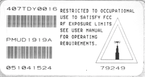
Click to zoom
Application Details
- Equipment Class
- TNF - Licensed Non-Broadcast Transmitter Held to Face
- Date of Grant
- Apr 20, 2004
- Application Purpose
- Original Equipment
- Date of Application
- Feb 29, 2004
- Equipment Note
- Astro XTS2500 Digital Portable Radio
- Frequency Range
- 136.00000000 - 174.00000000
- Company
- Motorola Solutions, Inc.
- Country
- United States
Documents & Files
Document Text
Text extracted from the exhibit documents filed with the FCC. Open a document above to read the original.
Users Manual
ASTRO ® XTS™ 2500 Digital Portable Radio Model III User Guide 6881094C06-B MOTOROLA, the Stylized M Logo, ASTRO, and CommPort are registered in the U.S. Patent & Trademark Office. All other product or service names are the property of their respective owners. P25 radios contain technology patented by Digital Voice Systems, Inc. © Motorola, Inc. 2002. All Rights Reserved. Printed in the U.S.A. 2/20/04. Motorola, Inc. 8000 W. Sunrise Blvd. Ft. Lauderdale, FL 33322 ii Product Safety and RF Exposure Compliance A TTENTION! This radio is restricted to occupational use only to satisfy FCC RF energy exposure requirements. Before using this product, read the RF energy awareness information and operating instructions in the Product Safety and RF Exposure booklet enclosed with your radio (Motorola Publication part number 6881095C98) to ensure compliance with RF energy exposure limits. For a list of Motorola-approved antennas, batteries, and other accessories, visit the following web site which lists approved accessories: < http://www .motorola.com/cgiss/index.shtml> Computer Software Copyrights The Motorola products described in this manual may include copyrighted Motorola computer programs stored in semiconductor memories or other media. Laws in the United States and other countries preserve for Motorola certain exclusive rights for copyrighted computer programs, including, but not limited to, the exclusive right to copy or reproduce in any form the copyrighted computer program. Accordingly, any copyrighted Motorola computer programs contained in the Motorola products described in this manual may not be copied, reproduced, modified, reverse-engineered, or distributed in any manner without the express written permission of Motorola. Furthermore, the purchase of Motorola products shall not be deemed to grant either directly or by implication, estoppel, or otherwise, any license under the copyrights, patents or patent applications of Motorola, except for the normal non-exclusive license to use that arises by operation of law in the sale of a product. Documentation Copyrights No duplication or distribution of this document or any portion thereof shall take place without the express written permission of Motorola. No part of this manual may be reproduced, distributed, or transmitted in any form or by any means, electronic or mechanical, for any purpose without the express written permission of Motorola. Disclaimer The information in this document is carefully examined, and is believed to be entirely reliable. However, no responsibility is assumed for inaccuracies. Furthermore, Motorola reserves the right to make changes to any products herein to improve readability, function, or design. Motorola does not assume any liability arising out of the applications or use of any product or circuit described herein; nor does it cover any license under its patent rights, nor the rights of others. Before using this product, read the operating instructions for safe usage contained in the Product Safety and RF Exposure booklet enclosed with your radio. ! C a u t i o n ASTRO XTS 2500 Model III iii Contents Product Safety and RF Exposure Compliance ................................. iiComputer Software Copyrights ......................................................... iiDocumentation Copyrights ................................................................ iiDisclaimer ......................................................................................... ii Safety . . . . . . . . . . . . . . . . . . . . . . . . . . . . . . . . . . . . . . . 1 Product Safety and RF Exposure Compliance .................................1 General Radio Operation . . . . . . . . . . . . . . . . . . . . . . . 3 Notations Used in This Manual .........................................................3XTS 2500 Model III Radio .................................................................4Physical Features of the XTS 2500 Model III Radio .................................................................5Programmable Features ...................................................................6Display ..............................................................................................7Backlight ...........................................................................................7Status Symbols .................................................................................8Menu Entry (Softkey) ........................................................................9Menu Select Buttons .........................................................................9 Menu Entry Features ................................................................10 Home Button ( h ) ............................................................................ 11 App Button (@) ............................................................................... 114-Way Navigation Button ( o ) ......................................................... 11 Keypad ............................................................................................12LED Indicators ................................................................................13Alert Tones ......................................................................................14Standard Accessories .....................................................................17 Battery ......................................................................................17Smart Battery Condition ...........................................................19Antenna ....................................................................................20Belt Clip ....................................................................................21 Universal Connector Cover .............................................................22Remote Speaker Microphone Adapter ............................................23Radio On and Off .....................................................................…
Text truncated - open the document above for the full version.
Users Manual
ASTRO XTS 2500 Model III83 Accessories Motorola provides the following approved accessories to improve the productivity of your XTS 2500 portable two-way radio. For a list of Motorola-approved antennas, batteries, and other accessories, visit the following web site which lists approved accessories: http://www.motorola.com/cgiss/index.shtml Antennas Batteries NAD6563VHF whip (136–174 MHz) NAD6566VHF (136–150.8 MHz) NAD6567VHF (150.8–162 MHz) NAD6568VHF (162–174 MHz) NAE6546UHF (403–435 MHz) NAE6547UHF (435–470 MHz) NAE6548UHF (470–520 MHz) NAE6549UHF whip (403–520 MHz) NAF5037800 MHz whip, halfwave (806–870 MHz) NAF5039800 MHz dipole (806–870 MHz) NAF5042800 MHz stubby, quarterwave (806–870 MHz) NAF5080700/800 MHz whip (764–870 MHz) NTN9815NiCd high-capacity NTN9816NiCd high-capacity, Factory Mutual Intrinsically Safe NTN9857NiMH ultra-high-capacity, Factory Mutual Intrinsically Safe NTN9858NiMH ultra-high-capacity 84 Accessories Carry Accessories Belt Clips Body-Worn Chargers HLN6853Belt clip, 2 1/4 inch NNTN4115Carrying case, leather with 3-in. swivel belt loop and T-strap NNTN4116Carrying case, leather with 2.5-in. swivel belt loop and T-strap NNTN4117Carrying case, leather with 3-in. belt loop and T-strap NLN6349Shoulder strap for carrying radio NTN5243Shoulder strap for carrying radio TDN9675Wrist strap for carrying radio NLN7967Wall-mount kit for multi-unit charger NLN7968Rack-mount kit for multi-unit charger NTN1168Single-unit dual rate, rapid charger 120V NTN1169Single-unit dual rate, rapid charger 220V (2-prong Euro plug) NTN1170Single-unit dual rate, rapid charger 240V (3-prong UK plug) NTN1177Multi-unit, dual rate, rapid charger 110V NTN1178Multi-unit, dual rate, rapid charger 240V (3-prong UK plug) NTN1179Multi-unit, rapid charger 240V (UK 13 MAP Plug) ASTRO XTS 2500 Model III85 Accessories Enhanced and Multi-Unit Line Cords Microphones, Remote Speaker NTN1667Tri-chemistry, 110V NTN1668Tri-Chemistry, 220V Single Unit Charger (2 Prong Euro Plug) NTN1669Tri-chemistry, 230V NTN1873IMPRES™ rapid charger 110V single-unit NTN1874IMPRES™ rapid charger 220V single-unit NTN1875IMPRES™ rapid charger 240V single-unit NTN4796Multi-unit, tri-chemistry, rapid rate, 110V NTN7209Single-unit dual rate, rapid charger w/o cord NTN7373110V interchangeable line NTN7374220V interchangeable line (2-prong Euro plug) NTN7375240V interchangeable line (3-prong UK plug) NMN6191Remote speaker mic, noise-canceling (includes 6.0-ft coiled cord assembly, 3.5-mm earjack, swivel clip, quick disconnect) NMN6193Remote speaker mic NNTN4285Remote speaker mic adapter ZMN6031Speaker mic, 3-piece ZMN6032Speaker mic, 2-piece ZMN6038Speaker mic, 2-piece, extra loud ZMN6039Speaker mic, 3-piece, extra loud 86 Accessories Surveillance Accessories CommPort ® Integrated Microphone/Receivers Earpieces NTN1624CommPort with palm PTT NTN1625CommPort ear mic with PTT for noise levels up to 100 dB (requires BDN6676 adapter) NTN1663CommPort ear mic with ring PTT for noise levels up to 100 dB (requires BDN6676 adapter) NTN1736CommPort ear mic with snap-on side PTT for noise levels up to 100 dB (requires BDN6676 adapter) BDN6641Ear mic, high noise level up to 105 dB, grey (must order BDN6671 interface module) BDN6664Earpiece with standard earphone, beige BDN6665Earpiece with extra-loud earphone (exceeds OSHA limits), beige BDN6666Earpiece with volume control, beige BDN6667Earpiece, mic and PTT combined, beige BDN6668Earpiece, mic and PTT separate, beige BDN6669Earpiece, mic and PTT combined, with extra-loud earphone (exceeds OSHA limits), beige BDN6670Earpiece, mic and PTT separate with extra-loud ear- phone (exceeds OSHA limits), beige BDN6677Ear mic, standard, noise up to 95 dB (must order BDN6671 interface module), black BDN6678Ear mic, standard, noise up to 95 dB (must order BDN6671 interface module), beige BDN6719Earpad, with 3.5mm threaded plug ASTRO XTS 2500 Model III87 Accessories Headsets and Headset Accessories BDN6726Earpiece with standard earphone, black BDN6727Earpiece with extra-loud earphone (exceeds OSHA limits), black BDN6728Earpiece with volume control, black BDN6729Earpiece, mic and PTT combined, black BDN6730Earpiece, mic and PTT separate, black BDN6731Earpiece, mic and PTT combined, with extra-loud earphone (exceeds OSHA limits), black BDN6732Earpiece, mic and PTT separate, with extra-loud earphone (exceeds OSHA limits), black BDN6780Earbud, single with mic and PTT combined, beige BDN6781Earbud, single, receive only, black BDN6635Heavy-duty VOX headset with noise-canceling boom mic (requires BDN6673 adapter) BDN6636Heavy-duty VOX headset with throat mic (requires BDN6673) BDN6645Noise-canceling boom mic headset with PTT on earcup BDN6673Headset adapter cable (for use with BDN6635 and BDN6645) BDN6676Jedi adapter NMN1020Safety helmet headset (requires BDN6676 adapter) NMN6245Light-weight headset NMN6246Ultralite headset with boom mic NMN6258Over-the-head headset with in-line PTT NMN6259Medium-weight, dual headset with NC mic RMN4049Jedi “TEMCO” temple transducer 88 Accessories Radio Interface Modules for Ear Microphones Switches BDN6671Push-to-talk (PTT) and voice-activated (VOX) inter- face module (for use with BDN6641, BDN6677 and BDN6678) BDN6708PTT interface module (for use with BDN6641, BDN6677 and BDN6678) 0180300E83 Remote PTT body switch NTN7660Tilt / man down switch
Users Manual
ASTRO XTS 2500 Model I1 Appendix: Maritime Radio Use in the VHF Frequency Range Special Channel Assignments Emergency Channel If you are in imminent and grave danger at sea and require emergency assistance, use VHF Channel 16 to send a distress call to nearby vessels and the United States Coast Guard. Transmit the following information, in this order: 1“MAYDAY, MAYDAY, MAYDAY.” 2“THIS IS _____________________, CALL SIGN __________.” State the name of the vessel in distress 3 times, followed by the call sign or other identification of the vessel, stated 3 times. 3Repeat “MAYDAY” and the name of the vessel. 4“WE ARE LOCATED AT _______________________.” State the position of the vessel in distress, using any information that will help responders to locate you, e.g.: • latitude and longitude • bearing (state whether you are using true or magnetic north) • distance to a well-known landmark • vessel course, speed or destination 5State the nature of the distress. 6Specify what kind of assistance you need. 7State the number of persons on board and the number needing medical attention, if any. 8Mention any other information that would be helpful to responders, such as type of vessel, vessel length and/or tonnage, hull color, etc. 9“OVER.” 10Wait for a response. 11If you do not receive an immediate response, remain by the radio and repeat the transmission at intervals until you receive a response. Be prepared to follow any instructions given to you. 2 Appendix: Maritime Radio Use in the VHF Frequency Range Non-Commercial Call Channel For non-commercial transmissions, such as fishing reports, rendezvous arrangements, repair scheduling, or berthing information, use VHF Channel 9. Operating Frequency Requirements A radio designated for shipboard use must comply with Federal Communications Commission Rule Part 80 as follows: • on ships subject to Part II of Title III of the Communications Act, the radio must be capable of operating on the 156.800 MHz frequency • on ships subject to the Safety Convention, the radio must be capable of operating: • in the simplex mode on the ship station transmitting frequencies specified in the 156.025–157.425 MHz frequency band, and • in the semiduplex mode on the two frequency channels specified in the table below. Note:Simplex channels 3, 21, 23, 61, 64, 81, 82, and 83 cannot be lawfully used by the general public in US waters. Additional information about operating requirements in the Maritime Services can be obtained from the full text of FCC Rule Part 80 and from the US Coast Guard. Table A-1: VHF Marine Channel List Channel Number Frequency (MHz) TransmitReceive 1156.050160.650 2156.100160.700 *156.150160.750 4156.200160.800 5156.250160.850 6156.300– 7156.350160.950 ASTRO XTS 2500 Model I3 Appendix: Maritime Radio Use in the VHF Frequency Range 8156.400– 9156.450156.450 10156.500156.500 11156.550156.550 12156.600156.600 13**156.650156.650 14156.700156.700 15**156.750156.750 16156.800156.800 17**156.850156.850 18156.900161.500 19156.950161.550 20157.000161.600 *157.050161.650 22157.100161.700 *157.150161.750 24157.200161.800 25157.250161.850 26157.300161.900 27157.350161.950 28157.400162.000 60156.025160.625 *156.075160.675 62156.125160.725 63156.175160.775 *156.225160.825 65156.275160.875 66156.325160.925 Table A-1: VHF Marine Channel List (Continued) Channel Number Frequency (MHz) TransmitReceive 4 Appendix: Maritime Radio Use in the VHF Frequency Range *Simplex channels 3, 21, 23, 61, 64, 81, 82, and 83 cannot be lawfully used by the general public in US waters. ** Low power (1 W) only *** Guard band Note:A – in the Receive column indicates that the channel is transmit only. 67**156.375156.375 68156.425156.425 69156.475156.475 71156.575156.575 72156.625– 73156.675156.675 74156.725156.725 75****** 76****** 77**156.875– 78156.925161.525 79156.975161.575 80157.025161.625 *157.075161.675 *157.125161.725 *157.175161.775 84157.225161.825 85157.275161.875 86157.325161.925 87157.375161.975 88157.425162.025 Table A-1: VHF Marine Channel List (Continued) Channel Number Frequency (MHz) TransmitReceive
Attestation Statements
Applicant: Motorola Inc. FCC ID: AZ489FT3807 EXHIBIT 2 SHEET 1 OF 1 EXHIBIT 2 CERTIFICATION OF DATA Pursuant to 47 CFR 2.907 The technical data supplied with this application, having been taken under my supervision is hereby duly certified. The following is a statement of my qualifications: 1) I received an Electrical and Telecommunication Engineering degree from University of Malaya, Malaysia. 2) I have 1 year experience in developing, testing, and certifying Land Mobile Communications Products. NAME: Muhammad Firdaus Fadzil SIGNATURE: /s/ FIRDAUS (signed) DATE: 26 th February 2004 POSITION: Electrical Engineer 3) I hereby certify that the above application was prepared under my direction and that to the best of my knowledge and belief, the facts set forth in the application and accompanying technical data are true and correct. NAME: Mohd Mirza Mohamed Noor SIGNATURE: /s/ MIRZA (signed) DATE: 26 th February 2004 POSITION: Manager
Cover Letter(s)
FCC ID: AZ489FT3807 EXHIBIT 13A SHEET 1 Date: 26 th February 2004 Authorization & Evaluation Division Federal Communications Commission Laboratory 7435 Oakland Mills Road Columbia, MD 21046 Application for Certification of Transmitter with FCC ID:AZ489FT3807 Dear Sir / Madam, Motorola Inc., 8000 West Sunrise Blvd., Fort Lauderdale, FL, herein submits application for Certification of the equipment identified by FCC ID number AZ489FT3807. This transmitter is primarily intended for use in a portable radio application with capabilities for conventional communications with a conducted transmit power which is adjustable from 1 Watt (+30 dBm) to 5.7 Watts (+37.6 dBm). The subject transmitter complies with CFR Title 47, Section 90.203, in that the operator cannot directly program the transmit frequencies using only the normally accessible external controls of the unit. Enclosed is a complete Certification Application comprised of 12 Exhibits. Contact me at (954) 723-5793 if you require any additional information. Sincerely, /s/ Mike Ramnath (signed) Manager, Regulatory Compliance Email: [email protected]
Cover Letter(s)
FCC ID: AZ489FT3807 EXHIBIT 13B SHEET 1 REQUEST FOR CONFIDENTIALITY Date: 26 th February 2004 Authorization & Evaluation Division Federal Communications Commission Laboratory 7435 Oakland Mills Road Columbia, MD 21046 Application for Certification of Transmitter with FCC ID:AZ489FT3807 Dear Sir / Madam, Motorola is requesting that Exhibit 4 (Circuit Descriptions), Exhibit 5 (Schematic Diagrams), Exhibit 10 (Parts List and Tune Up Procedures), and Exhibit 12 (Operational Description) not be made routinely available for public inspection. Motorola considers the information in these exhibits to be classified as trade secrets, pursuant to 47 CFR Section 0.457(d) and Section 552(b)(4) of the Freedom of Information Act. Please mark Exhibits 4, 5, 10, and 12 as “Confidential.” Contact me at (954) 723-5793 if you require any additional information. Sincerely, /s/ Mike Ramnath (signed) Manager, Regulatory Compliance Email: [email protected]
Cover Letter(s)
FCC ID: AZ489FT3807 15 th April 2004 Mr. Andy Leimer Equipment Authorization Branch Federal Communications Commission Laboratory 7435 Oakland Mills Road Columbia, MD 21046 Re: Form 731 Confirmation Number: EA841085 with FCC ID: AZ489FT3807. Dear Mr. Leimer; Motorola Inc., 8000 West Sunrise Boulevard, Fort Lauderdale, Florida 33322, herein submits its response to the 6 th April 2004 request for information in Correspondence Number 26620. Q1) fyi user manual pg84 (.pdf pg92) says 800mhz antennas are compatible - seems incorrect. R1) See the attached addendum Accessories Section of the User Manual with the additional antenna information. Q2) SAR report 4.3 refers to "IEEE Head" which is not applicable for 150 MHz range - in future reports please clarify/revise this. R2) We are taking your recommendation under consideration for future filings. Q3) SAR report 4.3 has tissue composition for 300 MHz - what is composition for 150 MHz range? R3) The table presented below presents simulant tissue composition for 150MHz and 300MHz. The simulant tissue used for both 300MHz and 150MHz meets the target parameters specified in FCC Supplement C. Tissue Ingredients (%) 300MHz 150MHz Head Body Head Body Sugar 56.0 47.1 55.4 49.7 DGBE (Glycol) NA NA NA NA De ionized -Water 37.5 49.48 38.35 46.2 Salt 5.4 2.32 5.15 2.8 HEC 1 1 1 1 Bact. 0.1 0.1 0.1 0.1 FCC ID: AZ489FT3807 Q4) SAR system check reported expanded uncertainty is 17%. SAR sect. 4.1 has 1g SAR = 2.81 +/- 0.090 for body, and SAR = 2.83 +/- 0.020 for head. How are 0.09 and 0.02 derived, and how are these related to 17% sys. check uncertainty? R4) Section 4.1 demonstrates compliance to the system verification guidance set forth in APPENDIX D in FCC Supplement C. The system performance results for each body location is compared to the system verification target results normalized to 1 watt as recommended by Supplement C. +/- 0.09 and +/- 0.02 reflect the delta from the presented multi-day median performance for each body location. For example: 2.81 +/- 0.09 represent a system performance range at the body of 2.72-2.90 for the five test days reported and also demonstrates adherence to the allowed 10% tolerance. The 17% expanded system uncertainty budget has no direct significance to the information presented in section 4.1. Q5) For SAR sect. 5 - in future filings please consider to add sub-numbering here with correspondent row numbers in data matrices of sect. 7. R5) We are taking your recommendation under consideration for future filings. Q6) For this and future filings please include purpose and description of SAR shortened scan, including grid spacings for full vs shortened scans, etc. R6) Part 1 of 2 Section 7.0 of the submitted report explains the purpose of the shortened scan and directs the reader to the DASY cube scan outputs in part 2 of 2 APPENDIX A which includes test parameters of the measured shortened scans for the worst case test configuration at each body location. The representative normal scan information is provided as well. The shortened scan was previously requested via FCC correspondence 22631, dated 4/16/02, by Martin Perrine, regarding FCC ID: ABZ99FT5000, in order to validate Motorola’s reported compliance results that are scaled to the maximum power of the DUT. The following is taken directly from correspondence 22631. 4) Data to validate the calculation made to account for power drift. Please provide: a plot of conducted power versus time (at least 30 minutes) for each of the batteries, a “shortened “ scan SAR measurement that focuses in on the hot spot and makes a measurement in minimal time. A measurement for the highest SAR point for body worn and held-to-face configurations should suffice. For reference purposes please repeat the original measurement to establish that the configuration is the same as previously reported. Motorola submitted a response to FCC correspondence 22631 on 4/26/02. The initial grant was issued on 5/3/2002. Please reference the submitted response along with the associated attachment entitled “Shortened scan results” for the format that was accepted. Motorola has subsequently included shortened scan information in the accepted format. Q7) You applied for Part 80 and Part 90. There does not appear to be any information in the application to support Part 80. The User's Manual does not contain any Part 80 information. Please explain. In addition, the User's Manual should have a Part 80 channel utilization chart. FCC ID: AZ489FT3807 R7) The data provided in the Exhibit 6 of the in the submission either meets or exceeds the technical requirements for Rule Part 80. Also, see the attached addendum to the User Manual with the Rule Part 80 channel utilization chart. Please contact me at (954) 723-5793 if you require any additional information. Sincerely, /s/ Mike Ramnath (signed) Manager, Regulatory Compliance Email: [email protected]
External Photos
Applicant: Motorola Inc. FCC ID: AZ489FT3807 EXHIBIT 3 SHEET 1 OF 10 EXHIBIT 3 EXTERNAL PHOTOGRAPHS Pursuant to 47 CFR 2.1033(c) 12 Figure 3-1: Front view of display and full keypad radio Applicant: Motorola Inc. FCC ID: AZ489FT3807 EXHIBIT 3 SHEET 2 OF 10 Figure 3-2: Front view of display and half keypad radio Applicant: Motorola Inc. FCC ID: AZ489FT3807 EXHIBIT 3 SHEET 3 OF 10 Figure 3-3: Front view of no display and no keypad radio Applicant: Motorola Inc. FCC ID: AZ489FT3807 EXHIBIT 3 SHEET 4 OF 10 Figure 3-4: Back view of complete radio Applicant: Motorola Inc. FCC ID: AZ489FT3807 EXHIBIT 3 SHEET 5 OF 10 Figure 3-5: Right side (side connector) view of complete radio Applicant: Motorola Inc. FCC ID: AZ489FT3807 EXHIBIT 3 SHEET 6 OF 10 Figure 3-6: Left side (PTT) view of complete radio Applicant: Motorola Inc. FCC ID: AZ489FT3807 EXHIBIT 3 SHEET 7 OF 10 Figure 3-7: Rear view of radio showing FCC & Safety labels location Safety Label Location FCC Label Location Applicant: Motorola Inc. FCC ID: AZ489FT3807 EXHIBIT 3 SHEET 8 OF 10 Figure 3-8: Close-up view of FCC RF Safety Label Applicant: Motorola Inc. FCC ID: AZ489FT3807 EXHIBIT 3 SHEET 9 OF 10 Figure 3-9: Types of Antenna Helical Whip NAD 6563A (Red) Helical Whip NAD 6568A (Blue) Helical NAD 6566A (Yellow) Helical Whip NAD 6567A (Black) Applicant: Motorola Inc. FCC ID: AZ489FT3807 EXHIBIT 3 SHEET 10 OF 10 Model List Sales Model Number Name Plates Descriptions H46KDC9PW5AN H46KDF9PW6AN H46KDH9PW7AN H66KDC9PW5AN H66KDC9PW5AN H66KDC9PW5AN H67KDC9PW5AN H67KDC9PW5AN XTS2500 XTS2500 XTS2500 XTS1500 XTS1500 XTS1500 MT1500 MT1500 VHF, 12.5/25KHz 1 – 5 Watt ASTRO25 No keypad, no display VHF, 12.5/25KHz 1 – 5 Watt ASTRO25 3x2 keypad, 6-line display VHF, 12.5/25KHz 1 – 5 Watt ASTRO25 3x6 keypad, 6-line display VHF, 12.5/25KHz 1 – 5 Watt ASTRO25 No keypad, no display VHF, 12.5/25KHz 1 – 5 Watt ASTRO25 3x2 keypad, 6-line display VHF, 12.5/25KHz 1 – 5 Watt ASTRO25 3x6 keypad, 6-line display VHF, 12.5/25KHz 1 – 5 Watt Analog Trunking, No keypad, no display VHF, 12.5/25KHz 1 – 5 Watt Analog Conventional, No keypad, no display
ID Label/Location Info
Applicant: Motorola Inc. FCC ID: AZ489FT3807 EXHIBIT 1 SHEET 1 OF 1 EXHIBIT 1 IDENTIFICATION LABEL Pursuant to 47 CFR 2.925(a), 2.1033(c), 2.0165 EXHIBIT 1A - LABEL LOCATION A nameplate of the type presented below will be affixed to every transmitter. It will be placed on the bottom of the unit near the front. Shown below is a photo of the actual label affixed to the cast chassis of the transmitter. Figure 1-1: FCC Label EXHIBIT 1B - GENERAL INFORMATION 1. Application References: TIA/EIA-603B Land Mobile FM or PM Communications Equipment Measurement and Performance Standards Code of Federal Regulations Title 47, Part 2, Sec. 2.1033-2.1057, Sec. 2.1077(a), Part 80 and Part 90, Section 90.210. 2. Data Submittal Procedure: Data is supplied in accordance with Part 2, Sub-part J of the Commission’s rules. The intended use of this transceiver includes applications covered in the Code of Federal Regulations Title 47, Part 80 and Part 90. Maximum transmitter power shall not be adjustable by the user. 3. Applicable Reference • Reference Certification FCC ID: AZ489FT3807 • EIA/TIA-603 Land Mobile FM or PM Communications Equipment Measurement and Performance Standards. • FCC Federal Regulations Part 47 Sec. 2.1033-2.1057 • FCC Federal Regulations Part 80, Marine Application • FCC Federal Regulations Part 90 Sec.90.210
Internal Photos
Applicant: Motorola Inc. FCC ID: AZ489FT3807 EXHIBIT 9 SHEET 1 OF 3 EXHIBIT 9 INTERNAL PHOTOGRAPHS Pursuant to 47 CFR 2.1033(c)12 Figure 9-1: Top Side of PCB (with shields) Figure 9-2: Top Side of PCB (without shields) Applicant: Motorola Inc. FCC ID: AZ489FT3807 EXHIBIT 9 SHEET 2 OF 3 Figure 9-3: Bottom Side of PCB (with shields) Figure 9-4: Bottom Side of PCB (without shields) Applicant: Motorola Inc. FCC ID: AZ489FT3807 EXHIBIT 9 SHEET 3 OF 3 Figure 9-5: Top View of chassis. Figure 9-6: Bottom View of chassis.
RF Exposure Info
CGISS EME Form-SAR-Rpt-Rev. 2.00 Page 1 of 24 CGISS EME Test Laboratory 8000 West Sunrise Blvd Fort Lauderdale, FL. 33322 S.A.R. EME Compliance Test Report Part 1 of 2 Note: Based on the information and the testing results provided herein, the undersigned certifies that when used as stated in the operating instructions supplied, said product complies with the national and international reference standards and guidelines listed in section 2.0 of this report. Signature on File 2/27/04 ____________________________________________________________ _________________________ Ken Enger Date Approved Senior Resource Manager, Laboratory Director, CGISS EME Lab Note: This report shall not be reproduced without written approval from an officially designated representative of the Motorola EME Laboratory. Date of Report: February 26, 2004 Report Revision: Rev. O Manufacturer: Motorola Product Description: XTS2500 digital; 136-174MHz, 5.0 watts nominal; 48 channel FCC ID: AZ489FT3807 Device Model: H46KDH9PW7AN Certificate Number: 1449-01 Test Period: 2/6/04-2/16/04 EME Tech: Clint Miller EME Eng.: Kim Uong (Sr. EME Eng.) Author: Michael Sailsman Global EME Regulatory Affairs Liaison CGISS EME Form-SAR-Rpt-Rev. 2.00 Page 2 of 24 TABLE OF CONTENTS Part 1 of 2 1.0 Introduction 2.0 Reference Standards and Guidelines 3.0 Description of Test Sample 3.1 Test Signal 3.2 Test Output Power 4.0 Description of Test Equipment 4.1 Description of S.A.R Measurement System 4.2 Description of Phantom 4.2.1 Flat Phantom 4.2.2 SAM phantom 4.3 Simulated Tissue Properties 4.3.1 Type of Simulated Tissue 4.3.2 Simulated Tissue Composition (System Performance) 4.4 Test conditions 5.0 Description of Test Procedure 5.1 Device Test Positions 5.1.1 Body 5.1.2 Head 5.1.3 Face 5.2 Test Position Photographs 5.3 Probe Scan Procedures 6.0 Measurement Uncertainty 7.0 S.A.R. Test Results 7.1 S.A.R. results 7.2 Peak S.A.R. location 7.3 Highest S.A.R. results calculation methodology 8.0 Conclusion Part 2 of 2 Appendix A: Power Slump Data/Shortened scan Appendix B: Data Results Appendix C: Dipole System Performance Check Results Appendix D: Calibration Certificates Appendix E: Illustration of Body-worn Accessories Appendix F: Accessories and options test status and separation distances CGISS EME Form-SAR-Rpt-Rev. 2.00 Page 3 of 24 REVISION HISTORY Date Revision Comments 2/26/04 O Release of Pilot results CGISS EME Form-SAR-Rpt-Rev. 2.00 Page 4 of 24 1.0 Introduction This report details the utilization, test setup, test equipment, and test results of the Specific Absorption Rate (S.A.R.) measurements performed at the CGISS EME Test Lab for model number H46KDH9PW7AN, FCC ID: AZ489FT3807. Th…
Text truncated - open the document above for the full version.
Contact Information
Applicant
Arine Lee(Certification Manager)
Technical Contact
Motorola IncMike Ramnath
[email protected]954-723-58793
8000 West Sunrise Blvd · Ft. Lauderdale, Florida · United States
Technical Specifications
| # | Rule Parts | Frequency Range | Power Output | Emission | Tolerance |
|---|---|---|---|---|---|
| 8 | 8 | 136 MHz - 174 MHz | 5.7 W | 8K10F1E | 2.5 ppm |
Other Applications from Motorola Solutions, Inc.

AZ489FT4980
Sep 08, 2026Portable two way radio
Equipment Class
TNF - Licensed Non-Broadcast Transmitter Held to FaceAZ489FT4981
Aug 14, 2026Handheld Portable - TANAPA BPR 45 400-470 MHZ 4W NKP
Equipment Class
TNF - Licensed Non-Broadcast Transmitter Held to Face
AZ489FT7187
Jul 13, 2026Portable 2-Way Radio with Bluetooth, Bluetooth LE, WIFI 2.4GHz, WIFI 5GHz, LTE
Equipment Class
DSS - Part 15 Spread Spectrum TransmitterAZ499FT6031
May 11, 2026Operation Critical Wireless Earpiece PTT
Equipment Class
DSS - Part 15 Spread Spectrum Transmitter
AZ499FT5879
Dec 19, 20252-way Portable Radio with BT, BTLE, WIFI, NFC and LTE
Equipment Class
DSS - Part 15 Spread Spectrum Transmitter