AZ489FT3809Portable Two-Way Portable Radio
Motorola Solutions, Inc.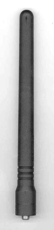
Click to zoom
Application Details
- Equipment Class
- TNF - Licensed Non-Broadcast Transmitter Held to Face
- Date of Grant
- Jun 04, 2006
- Application Purpose
- Original Equipment
- Date of Application
- Apr 26, 2006
- Equipment Note
- Portable Two-Way Portable Radio
- Frequency Range
- 136.00000000 - 150.00000000
- Company
- Motorola Solutions, Inc.
- Country
- United States
Documents & Files
Document Text
Text extracted from the exhibit documents filed with the FCC. Open a document above to read the original.
Users Manual
PRODUCT SAFETY AND RF EXPOSURE COMPLIANCE ATTENTION! This radio is restricted to occupational use only to satisfy FCC RF energy exposure requirements. Before using this product, read the RF energy awareness information and operating instructions in the Product Safety and RF Exposure booklet enclosed with your radio (Motorola Publication part number 6881095C98) to ensure compliance with RF energy exposure limits. For a list of Motorola-approved antennas, batteries, and other accessories, visit the following web site which lists approved accessories: http://www.motorola.com/governmentandenterprise Mag One™ by Motorola is registered in the U.S. Patent and Trademark Office. All other products and service names are the property of their own respective owners. © Motorola, Inc. 2005, 2006 1301 E. Algonquin Rd., Schaumburg, IL 60196 Printed in Korea. 03/06. All Rights Reserved. Before using this product, read the operating instructions for safe usage contained in the Product Safety and RF Exposure booklet enclosed with your radio. *6881098C61* 6881098C61-B Attaching and Removing the Antenna To Attach Antenna To Remove Antenna 1.Fasten the antenna to the radio by placing the threaded end of the antenna into the Antenna Connector. 2.Rotate the antenna clockwise until tight. 1.Turn the antenna in a counter-clockwise direction until it disengages from the radio. Threaded End of Antenna Antenna Connector Attaching and Removing the Battery To Attach Battery To Remove Battery 1.Align and fit the battery tongue into the groove of the chassis of the radio. 2.Secure the latch at the bottom of the radio. 1.Unlatch the battery clasp at the bottom of the radio. 2.Gently lift the hilt of the battery nearest to the battery latch away from the housing. 3.Slide battery downwards to remove. Attaching and Removing the Belt Clip To Attach Belt Clip To Remove Belt Clip 1.Align mounting rails of the radio with the grooves of the belt clip. 2.Slide the belt clip downwards until it clicks into place. 1.Lift the release tab. 2.Slide the belt clip upwards. Release Tab Charging your Radio 1.Turn off your radio and the A/C power sup- ply to your charger (if they are turned on). 2.Place your radio in the charger pocket. 3.Turn on the charger’s A/C power supply. 4.While charging your radio, the charger’s LED shows a steady red light. The radio should be charged at least 16 hours initially before decreasing charging time to 12 hours. 5.Turn off the charger’s A/C power supply, and remove the radio from the charger pocket. 6.For more details, refer to the Charger Manual (6881013Y27). Charger Pocket LED Indicators ColourStateIndication RedIlluminatedRadio is transmitting. BlinkingBattery voltage is low. GreenIlluminatedRadio is receiving with PL/DPL disabled. BlinkingRadio is in active scanning mode. OrangeIlluminatedRadio is receiving with PL/DPL enabled. BlinkingAn error has occured. On/Off and Volume Knob • Turn clockwise to turn radio ON and increase volume. • Turn counter-clockwise to decrease volume and turn radio OFF. Push-to-Talk (PTT) button • Press to transmit and release to receive messages. Speaker • Where received messages are heard. Microphone • Speak into microphone when send- ing message. Accessory Connector • To connect compatible acces- sories to radio. Programming Port • To program the radio. Accessories *Caution: Your radio does not support the VOX feature. Please set the accessory switch to ‘PTT’. If the accessory switch is set to ‘VOX’, your radio transmits constantly and never receives. TypesPart No.Description PMAD4050_RMag One 136-150MHz Antenna AntennaPMAD4051_RMag One 150-174MHz Antenna PMAE4019_RMag One 403-425MHz Antenna PMAE4020_RMag One 450-470MHz Antenna Audio AccessoryPMMN4008_Remote Speaker Microphone PMLN4442_Earbud with in-line mic and PTT/VOX * Switch PMLN4443_Ear Receiver with in-line mic and PTT/VOX* Switch PMLN4445_Ultra Lightweight Headset with In-line PTT/VOX * Switch PMLN4294_Earbud with Microphone & PTT Combined PMLN4605_Clear Acoustic Kit PMLN4606_2-Wire Surveillance Kit with Clear Acoustic Tube PMLN4658 _D-shell Earset with Boom Mic with PTT/VOX * Switch BatteryPMNN4071_RMag One NiMH batt 1200mAH Carry Accessory PMLN4743_Mag One Spring Belt Clip PMLN4691_RMag One Belt Clip PMLN4741_Mag One Soft Leather Carry Case PMLN4742_Mag One Hard Leather Carry Case ChargerPMLN4685_RMag One Mid-rate Charger Base Only PMLN4738_RMag One Mid-rate Charger Kit, 120 V PMLN4682_RMag One Slow Charger Base Only PMLN4683_RMag One Slow Charger Kit, 120 V PMLN4829_RMag One Mid-rate Transformer, 120 V PMLN4822_RMag One Slow Transformer, 120 V Channel Knob • Turn knob to change channel. Programmable Buttons • Frequently used features can be programmed here. LED Indicator • Colors indicate various states of the radio Programmable Buttons • The following functions can be assigned as short press (press and release) or long press (press and hold for 1 second) in the programmable buttons. † In Chirp Tone * Out Chirp Tone • Your radio’s default functions are described below. If re-programmed, enter the new functions . ButtonFunction High/Low Power Selects desired power level to High † or Low * . Volume SetAllows you to check the audio and alert tone volume level. MonitorAllows you to monitor the current channel for activity; disables squelch. Sticky Monitor * The radio monitors continually until you press this button again. Scan Starts * or Stops † channel scan. Nuisance Channel Delete † Removes unwanted channel(s) temporarily from scan list during scan. Repeater/Talkaround Toggles radio between functioning in Repeater mode † or Talkaround mode * . PL/DPL Enables † /Disables * radio from requiring matching PL/DPL to receive messages. Button Lock Locks * or unlocks † all buttons except PTT, Channel Knob and On/Off/Volume Knob. Battery Save Mode Toggles between functioning with Battery Saver ON * or Battery Saver OFF † . Squelch Selects desired squelch level: Normal † or Tight * . No OperationNo function is programmed…
Text truncated - open the document above for the full version.
Users Manual
English Product Safety and RF Energy Exposure Booklet for Portable Two-Way Radios The information provided in this document supersedes the general safety information contained in user guides published prior to February 2002. BEFORE USING THIS RADIO, READ THIS BOOKLET WHICH CONTAINS IMPORTANT OPERATING INSTRUCTIONS FOR SAFE USAGE AND RF ENERGY AWARENESS AND CONTROL INFORMATION AND OPERATIONAL INSTRUCTIONS FOR COMPLIANCE WITH RF ENERGY EXPOSURE LIMITS IN APPLICABLE NATIONAL AND INTERNATIONAL STANDARDS. ALSO READ THE OPERATIONAL INSTRUCTIONS FOR SAFE USAGE. FOR RADIOS THAT HAVE BEEN APPROVED AS INTRINSICALLY SAFE, READ THE INSTRUCTIONS AND INFORMATION ON INTRINSIC SAFETY ON PAGE 10 OF THIS BOOKLET. ! C a u t i o n © Motorola, Inc. 2003 8000 W. Sunrise Blvd., Ft. Lauderdale, FL 33322 Printed in U.S.A. 7/04. 68P81095C98 68P81095C98-C 2 English RF Energy Exposure Awareness and Control Information and Operational Instructions for Occupational Use NOTICE: This radio is intended for use in occupational/controlled conditions where users have full knowledge of their exposure and can exercise control over their exposure to meet the occupational limits in FCC and International standards. This radio device is NOT authorized for general population consumer use. This two-way radio uses electromagnetic energy in the radio frequency (RF) spectrum to provide communications between two or more users over a distance. It uses radio frequency (RF) energy or radio waves to send and receive calls. RF energy is one form of electromagnetic energy. Other forms include, but are not limited to, sunlight and x-rays. RF energy, however, should not be confused with these other forms of electromagnetic energy, which when used improperly, can cause biological damage. Very high levels of x-rays, for example, can damage tissues and genetic material. Experts in science, engineering, medicine, health, and industry work with organizations to develop standards for safe exposure to RF energy. These standards provide recommended levels of RF exposure for both workers and the general public. These recommended RF exposure levels include substantial margins of protection. All Motorola two-way radios are designed, manufactured, and tested to ensure they meet government-established RF exposure levels. In addition, manufacturers also recommend specific operating instructions to users of two-way radios. These instructions are important because they inform users about RF energy exposure and provide simple procedures on how to control it. 3 English Please refer to the following websites for more information on what RF energy exposure is and how to control your exposure to assure compliance with established RF exposure limits: http://www.fcc.gov/oet/rfsafety/rf-faqs.html http://www.osha.gov/SLTC/radiofrequencyradiation/index.html Federal Communication Commission (FCC) Regulations The FCC rules require manufacturers to comply with the FCC RF energy exposure limits for portable two-way radios before they can be marketed in the U.S. When two-way radios are used as a consequence of employment, the FCC requires users to be fully aware of and able to control their exposure to meet occupational requirements. Exposure awareness can be facilitated by the use of a product label directing users to specific user awareness information. Your Motorola two-way radio has a RF Exposure Product Label. Also, your Motorola user manual, or separate safety booklet includes information and operating instructions required to control your RF exposure and to satisfy compliance requirements. Compliance with RF Exposure Standards Your Motorola two-way radio is designed and tested to comply with a number of national and International standards and guidelines (listed below) for human exposure to radio frequency electromagnetic energy. This radio complies with the IEEE (FCC) and ICNIRP exposure limits for occupational/controlled RF exposure environments at operating duty factors of up to 50% talk-50% listen and is authorized by the FCC for occupational use only. In terms of measuring RF energy for compliance with these exposure guidelines, your radio generates measurable RF energy only while it is transmitting (during talking), not when it is receiving (listening) or in standby mode. NOTE:The approved batteries, supplied with this radio, are rated for a 5-5-90 duty factor (5% talk-5% listen-90% standby) even though this radio complies with FCC occupational exposure limits and may operate at duty factors of up to 50% talk. 4 English Your Motorola two-way radio complies with the following RF energy exposure standards and guidelines: • United States Federal Communications Commission, Code of Federal Regulations; 47CFR part 2 sub-part J • American National Standards Institute (ANSI) / Institute of Electrical and Electronic Engineers (IEEE) C95. 1-1992 • Institute of Electrical and Electronic Engineers (IEEE) C95.1-1999 Edition • International Commission on Non-Ionizing Radiation Protection (ICNIRP) 1998 • Ministry of Health (Canada) Safety Code 6. Limits of Human Exposure to Radiofrequency Electromagnetic Fields in the Frequency Range from 3 kHz to 300 GHz, 1999 • Australian Communications Authority Radiocommunications (Electromagnetic Radiation – Human Exposure) Standard, 2003 • ANATEL ANNEX to Resolution No. 303 of July 2, 2002 "Regulation of limitation of exposure to electrical, magnetic and electromagnetic fields in the radio frequency range between 9 KHz and 300 GHz" and "Attachment to resolution # 303 from July 2, 2002" RF Exposure Compliance and Control Guidelines and Operating Instructions To control your exposure and ensure compliance with the occupational/controlled environment exposure limits, always adhere to the following procedures. Guidelines: • Do not remove the RF Exposure Label from the device. • User awareness instructions should accompany device when transferred to other users. • Do not use this device if the operational requirements described herein are …
Text truncated - open the document above for the full version.
Attestation Statements
Applicant: Motorola Inc. FCC ID: AZ489FT3809 EXHIBIT 2 SHEET 1 OF 1 EXHIBIT 2 CERTIFICATION OF DATA: Pursuant to 47 CFR 2.907 The technical data supplied with this application, having been taken under my supervision is hereby duly certified. The following is a statement of my qualifications: 1) I received a BEEE degree from the University Technology Malaysia (UTM), Malaysia. 2) I have 7 years experience in developing, testing, and certifying Land Mobile Communications Products. NAME: Sumiyyah Abdul Kader SIGNATURE: /s/ SUMIYYAH (signed) DATE: April 25, 2006 POSITION: Electrical Engineer I hereby certify that the above application was prepared under my direction and that to the best of my knowledge and belief, the facts set forth in the application and accompanying technical data are true and correct. NAME: Michael Loh SIGNATURE: /s/ MICHAEL LOH (signed) DATE: April 25, 2006 POSITION: Engineering Manager
Cover Letter(s)
Date: 27 th April 2006 Authorization & Evaluation Division Federal Communications Commission Laboratory 7435 Oakland Mills Road Columbia, MD 21046 Application for Certification of Transmitter with FCC ID: AZ489FT3809 Dear Sir / Madam, Motorola Inc., 8000 West Sunrise Blvd., Fort Lauderdale, FL, herein submits application for Certification of the equipment identified by FCC ID:AZ489FT3809. This transmitter is primarily intended for use in a portable radio application with capabilities for conventional communications with a conducted transmit power which is adjustable from 1 to 5.5 Watts. The subject transmitter complies with CFR Title 47, Section 90.203, in that the operator cannot directly program the transmit frequencies using only the normally accessible external controls of the unit. Enclosed is a complete Certification Application. Please contact me if you require any additional information. Sincerely, /s/Mike Ramnath(signed) Mike Ramnath Manager, Regulatory Compliance Email: [email protected] EXHIBIT 13A SHEET 1
Cover Letter(s)
REQUEST FOR CONFIDENTIALITY 27 th April 2006 Authorization & Evaluation Division Federal Communications Commission Laboratory 7435 Oakland Mills Road Columbia, MD 21046 Application for Certification of Transmitter with FCC ID: AZ489FT3809 Dear Sir / Madam, Motorola is requesting that Exhibit 4 (Block Diagram), Exhibit 5 (Schematic Diagrams), Exhibit 10 (Parts List and Tune-Up Procedures), and Exhibit 12 (Operational Description) not be made routinely available for public inspection. Motorola considers the information in these exhibits to be classified as trade secrets, pursuant to 47 CFR Section 0.457(d) and Section 552(b)(4) of the Freedom of Information Act. We are also requesting that the FCC mark Exhibit 3 (External Photos), and Exhibit 9 (Internal Photos) as Temporary Confidentiality as outlined in Public Notice DA 04- 1705, dated June 15, 2004. This provision will give Motorola temporary confidentiality prior to product launch. Please mark Exhibits 4, 5, 10, and 12 as “Confidential” And Exhibit 3, and 9 as “Temporary Confidential”. Please contact me if you require any additional information. Sincerely, /s/ Mike Ramnath (signed) Mike Ramnath Manager, Regulatory Compliance Email: [email protected] EXHIBIT 13B SHEET 1
External Photos
Applicant: Motorola Inc. FCC ID: AZ489FT3809 EXHIBIT 3 SHEET 1 OF 7 EXHIBIT 3 EXTERNAL PHOTOGRAPHS: Pursuant to 47 CFR 2.1033(c) 12 Figure 3-1: Front view of complete radio Applicant: Motorola Inc. FCC ID: AZ489FT3809 EXHIBIT 3 SHEET 2 OF 7 Figure 3-2: Back view of complete radio Applicant: Motorola Inc. FCC ID: AZ489FT3809 EXHIBIT 3 SHEET 3 OF 7 Figure 3-3: Right side (side connector) view of complete radio Applicant: Motorola Inc. FCC ID: AZ489FT3809 EXHIBIT 3 SHEET 4 OF 7 Figure 3-4: Left side (PTT) view of complete radio Applicant: Motorola Inc. FCC ID: AZ489FT3809 EXHIBIT 3 SHEET 5 OF 7 FCC Label Location RF Safety Label Location Figure 3-5: Rear view of complete radio showing FCC Label & RF Safety Label location Applicant: Motorola Inc. FCC ID: AZ489FT3809 EXHIBIT 3 SHEET 6 OF 7 Figure 3-6: Top view of complete radio Figure 3-7: Close-up view of RF Safety Label Applicant: Motorola Inc. FCC ID: AZ489FT3809 EXHIBIT 3 SHEET 7 OF 7 Figure 3-8: Type of Antenna; Helical Antenna (PMAD4050A)
ID Label/Location Info
Applicant: Motorola Inc. FCC ID: AZ489FT3809 EXHIBIT 1 SHEET 1 OF 1 EXHIBIT 1 IDENTIFICATION LABEL Pursuant to 47 CFR 2.925(a), 2.1033(c), 2.0165 EXHIBIT 1A - LABEL LOCATION A nameplate of the type presented below will be affixed to every transmitter. It will be placed on the bottom of the unit near the front. Shown below is a photo of the actual label affixed to the cast chassis of the transmitter. Figure 1-1: FCC Label EXHIBIT 1B - GENERAL INFORMATION 1. Application References: TIA/EIA-603B Land Mobile FM or PM Communications Equipment Measurement and Performance Standards Code of Federal Regulations Title 47, Part 2, Sec. 2.1033-2.1057, Sec. 2.1077 (a) and Part 90, Section 90.210. 2. Data Submittal Procedure: Data is supplied in accordance with Part 2, Sub-part J of the Commission’s rules. The intended use of this transceiver includes applications covered in the Code of Federal Regulations Title 47 and Part 90. Maximum transmitter power shall not be adjustable by the user. 3. Applicable Reference • Reference Certification FCC ID: AZ489FT3809 • EIA/TIA-603 Land Mobile FM or PM Communications Equipment Measurement and Performance Standards. • FCC Federal Regulations Part 47 Sec. 2.1033-2.1057 • FCC Federal Regulations Part 90 Sec.90.210
Internal Photos
Applicant: Motorola Inc. FCC ID: AZ489FT3809 EXHIBIT 9 SHEET 1 OF 2 EXHIBIT 9 INTERNAL PHOTOGRAPHS - Pursuant to 47 CFR 2.1033(c) 12 Figure 9-1: Top Side of PCB. Figure 9-2: Bottom Side of PCB. Applicant: Motorola Inc. FCC ID: AZ489FT3809 EXHIBIT 9 SHEET 2 OF 2 Figure 9-3: Top View of chassis. Figure 9-4: Bottom View of chassis.
RF Exposure Info
FCC ID: AZ489FT3809 SR3747 GEMS EME Form-SAR-Rpt-Rev. 4.01 Page 1 of 52 Certificate Number: 1449-01 FCC ID: AZ489FT3809 DECLARATION OF COMPLIANCE SAR ASSESSMENT Networks & Enterprise EME Test Laboratory 8000 West Sunrise Blvd Fort Lauderdale, FL. 33322 Date of Report: 4/10/06 Report Revision: Rev O Report ID: FCC rpt_Alpha L VHF R1_060410_SR3747 Responsible Engineer: Michael Sailsman (Sr. Staff Eng.) Date/s Tested: 3/10/06-3/17/06 Manufacturer/Location: Motorola – Penang Sector/Group/Div.: NE/GTDG Date submitted for test: 3/7/06 DUT Description: 136-150MHZ 12.5/25K-16CH Test TX mode(s): CW Max. Power output: 5.5W Nominal Power: 5.0W Tx Frequency Bands: 136-150MHz Signaling type: FM Model(s) Tested: PMUD2221A/AAH84JDJ8AA1AN Model(s) Certified: PMUD2221A/AAH84JDJ8AA1AN Serial Number(s): 0277GD0211, 0277GD0209 Classification: Occupational/Controlled Rule Part(s): 90 Approved Accessories: Antenna(s): PMAD4050A (136-150MHz ¼ wave, -3dBi); PMAD4050AR (136-150MHz ¼ wave, -3dBi) Battery(ies): PMNN4071ARC (Mag One NiMH, 1200mAH: CHN-LBL, Boxed); PMNN4071A (Mag One NiMH, 1200mAH), PMNN4071AR (Mag One NiMH, 1200mAH: Boxed); PMNN4071AC (MAG One NiMH, 1200mAH: CHN-LBL) Body worn accessory(ies): PMLN4743A (Spring belt); PMLN4691A (Standard belt clip); PMLN4741A (soft leather carry case); PMLN4742A (hard leather carry case) Audio/Data cable accessory(ies): PMMN4008A (Remote speaker microphone); PMLN4442A (Earbud w/ in-line mic and PTT/VOX switch); PMLN4443A (Ear receiver w/ in- line mic and PTT/VOX switch); PMLN4444A (Earphone Boom mic w/ in-line mic and PTT/VOX switch); PMLN4445A (Ultra lightweight headset w/ in-line PTT/VOX switch); PMLN4294C (Earbud w/ combined microphone and PTT); PMLN4606A (2-wire surveillance kit w/ clear acoustic tube); PMLN4658A (D-shell earset w/ boom mic & PTT/VOX switch) Max. Calc. 1-g/10-g Avg. SAR: 2.10/1.15 W/kg (Body) Max. Calc. 1-g/10-g Avg. SAR: 1.15/0.86 W/kg (Face) Based on the information and the testing results provided herein, the undersigned certifies that when used as stated in the operating instructions supplied, said product complies with the national and international reference standards and guidelines listed in section 2.0 of this report. This report shall not be reproduced without written approval from an officially designated representative of the Motorola EME Laboratory. This reporting format is consistent with the test report guidelines of the TIA TSB-150 December 2004 The results and statements contained in this report pertain only to the device(s) evaluated. Ken Enger signature on file Ken Enger GEMS EME Lab Senior Resource Manager, Laboratory Director, Approval Date: 4/11/06 Certification Date: 4/11/06 Certification No.: L1060381 FCC ID: AZ489FT3809 SR3747 GEMS EME Form-SAR-Rpt-Rev. 4.01 Page 2 of 52 1.0 Introduction and Overview...................................................................................... 3 2.0 Referenced Standards and Guidelines ..................................................................... 3 2.1 SAR Limits ................................................................................................... 4 3.0 Description of Device Under Test (DUT) ............................................................... 4 4.0 Description of Test System ..................................................................................... 5 4.1 Description of Robotics/Probes/Readout Electronics ................................... 5 4.2 Description of Phantom(s) ............................................................................ 5 4.2.1 Flat Phantom................................................................................... 5 4.2.2 SAM Phantom ................................................................................ 6 4.3 Description of Equivalent Tissues ................................................................ 6 5.0 Additional Test Equipment...................................................................................... 7 6.0 SAR Measurement System Verification.................................................................. 7 6.1 Equivalent Tissue Test results ...................................................................... 7 6.2 System Check Test results ............................................................................ 8 7.0 DUT Test Strategy and Methodology ..................................................................... 8 7.1 DUT Configuration(s) .................................................................................. 8 7.2 Device Positioning Procedures ..................................................................... 9 7.2.1 Body ............................................................................................... 9 7.2.2 Head ............................................................................................... 9 7.2.3 Face ................................................................................................ 9 8.0 Environmental Test Conditions ............................................................................. 10 9.0 Test Results Summary ........................................................................................... 10 9.1 Highest SAR results calculation methodology ........................................... 12 10.0 Conclusion............................................................................................................. 12 APPENDICES A Measurement Uncertainty ..................................................................................... 13 B Probe Calibration Certificates ............................................................................... 16 C Dipole Calibration Certificates.............................................................................. 27 D Test System Verification Scans ............................................................................. 32 E DUT Scans (Highest SAR configurations)............................................................…
Text truncated - open the document above for the full version.
RF Exposure Info
FCC ID: AZ489FT3809 SR3747 GEMS EME Form-SAR-Rpt-Rev. 4.01 Page 35 of 52 Motorola GEMS EME Lab SPEAG 300 MHz Dipole; Model D300V2, SN 1002; Test Date: 3/12/06 Run #: MeC-Sys Perf-300B-060312-01 Sim.Tissue Temp: 21.2 (C) TX Freq: 300 (MHz) Start power: 250 (mW) Target: 2.79 mW/g for 1g SAR 1.83 mW/g for 10g SAR 2.71 mW/g calculated 1g-SAR; -2.92 % from target (including drift) 1.80 mW/g calculated 10g-SAR; -1.54 % from target (including drift) Probe: ET3DV6 - SN1393, Calibrated: 5/20/2005, ConvF(7.7, 7.7, 7.7) Duty Cycle: 1:1, Medium: 300 MHz Body, Medium parameters used: f = 300 MHz; σ = 0.9 mho/m; ε r = 57.9; ρ = 1000 kg/m 3; Electronics: DAE3 Sn363, Calibrated: 5/24/2005 System Performance Check/0-Degree 5x5x7 Cube (5x5x7)/Cube 0: Measurement grid: dx=7.5mm, dy=7.5mm, dz=5mm; Reference Value = 28.5 V/m; Power Drift = 0.00543 dB Peak SAR (extrapolated) = 1.17 W/kg SAR(1 g) = 0.694 mW/g; SAR(10 g) = 0.461 mW/g Maximum value of SAR (measured) = 0.730 mW/g System Performance Check/90-Degree 5x5x7 Cube (5x5x7)/Cube 0: Measurement grid: dx=7.5mm, dy=7.5mm, dz=5mm; Reference Value = 28.5 V/m; Power Drift = 0.00543 dB Peak SAR (extrapolated) = 1.11 W/kg SAR(1 g) = 0.661 mW/g; SAR(10 g) = 0.440 mW/g Maximum value of SAR (measured) = 0.692 mW/g System Performance Check/Dipole Area Scan (41x81x1): Measurement grid: dx=15mm, dy=15mm Reference Value = 28.5 V/m; Power Drift = 0.00543 dB FCC ID: AZ489FT3809 SR3747 GEMS EME Form-SAR-Rpt-Rev. 4.01 Page 36 of 52 Motorola GEMS EME Lab SPEAG 300 MHz Dipole; Model D300V2, SN 1002; Test Date: 3/14/06 Run #: ErC-Sys Perf-300H-060314-01 Sim.Tissue Temp: 21.5 (C) TX Freq: 300 (MHz) Start power: 250 (mW) Target: 2.85 mW/g for 1g SAR 1.87 mW/g for 10g SAR 2.92 mW/g calculated 1g-SAR; 2.35 % from target (including drift) 1.91 mW/g calculated 10g-SAR; 2.34 % from target (including drift) Probe: ET3DV6 - SN1393, Calibrated: 5/20/2005, ConvF(7.7, 7.7, 7.7) Duty Cycle: 1:1, Medium: 300 MHz Head, Medium parameters used: f = 300 MHz; σ = 0.88 mho/m; ε r = 45.9; ρ = 1000 kg/m 3;Electronics: DAE3 Sn363, Calibrated: 5/24/2005 System Performance Check/0-Degree 5x5x7 Cube (5x5x7)/Cube 0: Measurement grid: dx=7.5mm, dy=7.5mm, dz=5mm; Reference Value = 29.5 V/m; Power Drift = -0.0405 dB Peak SAR (extrapolated) = 1.23 W/kg SAR(1 g) = 0.723 mW/g; SAR(10 g) = 0.474 mW/g Maximum value of SAR (measured) = 0.764 mW/g System Performance Check/90-Degree 5x5x7 Cube (5x5x7)/Cube 0: Measurement grid: dx=7.5mm, dy=7.5mm, dz=5mm; Reference Value = 29.5 V/m; Power Drift = -0.0405 dB Peak SAR (extrapolated) = 1.23 W/kg SAR(1 g) = 0.722 mW/g; SAR(10 g) = 0.474 mW/g Maximum value of SAR (measured) = 0.763 mW/g System Performance Check/Dipole Area Scan (5x9x1): Measurement grid: dx=15mm, dy=15mm Maximum value of SAR (measured) = 0.766 mW/g FCC ID: AZ489FT3809 SR3747 GEMS EME Form-SAR-Rpt-Rev. 4.01 Page 37 of 52 Motorola GEMS EME Lab SPEAG 300 MHz Dipole; Model D300V2, SN 1002; Test Date: 3/16/06 Run #: MeC-Sys Perf-300B-060316-05 Sim.Tissue Temp: 21.0 (C) TX Freq: 300 (MHz) Start power: 250 (mW) Target: 2.79 mW/g for 1g SAR 1.83 mW/g for 10g SAR 2.64 mW/g calculated 1g-SAR; -5.25 % from target (including drift) 1.78 mW/g calculated 10g-SAR; -2.90 % from target (including drift) Probe: ET3DV6 - SN1393, Calibrated: 5/20/2005, ConvF(7.7, 7.7, 7.7) Duty Cycle: 1:1, Medium: 300 MHz Body, Medium parameters used: f = 300 MHz; σ = 0.88 mho/m; ε r = 58; ρ = 1000 kg/m3 Electronics: DAE3 Sn363, Calibrated: 5/24/2005 System Performance Check/0-Degree 5x5x7 Cube (5x5x7)/Cube 0: Measurement grid: dx=7.5mm, dy=7.5mm, dz=5mm; Reference Value = 28.1 V/m; Power Drift = 0.00757 dB Peak SAR (extrapolated) = 1.09 W/kg SAR(1 g) = 0.661 mW/g; SAR(10 g) = 0.444 mW/g Maximum value of SAR (measured) = 0.696 mW/g System Performance Check/90-Degree 5x5x7 Cube (5x5x7)/Cube 0: Measurement grid: dx=7.5mm, dy=7.5mm, dz=5mm; Reference Value = 28.1 V/m; Power Drift = 0.00757 dB Peak SAR (extrapolated) = 1.09 W/kg SAR(1 g) = 0.662 mW/g; SAR(10 g) = 0.445 mW/g Maximum value of SAR (measured) = 0.697 mW/g FCC ID: AZ489FT3809 SR3747 GEMS EME Form-SAR-Rpt-Rev. 4.01 Page 38 of 52 Motorola GEMS EME Lab SPEAG 300 MHz Dipole; Model D300V2, SN 1002; Test Date: 3/17/06 Run #: MeC-Sys Perf-300B-060317-02 Sim.Tissue Temp: 21.3 (C) TX Freq: 300 (MHz) Start power: 250 (mW) Target: 2.79 mW/g for 1g SAR 1.83 mW/g for 10g SAR 2.73 mW/g calculated 1g-SAR; -2.11 % from target (including drift) 1.81 mW/g calculated 10g-SAR; -1.01 % from target (including drift) Probe: ET3DV6 - SN1393, Calibrated: 5/20/2005, ConvF(7.7, 7.7, 7.7) Duty Cycle: 1:1, Medium: 300 MHz Body, Medium parameters used: f = 300 MHz; σ = 0.9 mho/m; ε r = 59.1; ρ = 1000 kg/m 3; Electronics: DAE3 Sn363, Calibrated: 5/24/2005 System Performance Check/0-Degree 5x5x7 Cube (5x5x7)/Cube 0: Measurement grid: dx=7.5mm, dy=7.5mm, dz=5mm; Reference Value = 28.1 V/m; Power Drift = 0.00133 dB Peak SAR (extrapolated) = 1.15 W/kg SAR(1 g) = 0.682 mW/g; SAR(10 g) = 0.451 mW/g Maximum value of SAR (measured) = 0.723 mW/g System Performance Check/90-Degree 5x5x7 Cube (5x5x7)/Cube 0: Measurement grid: dx=7.5mm, dy=7.5mm, dz=5mm; Reference Value = 28.1 V/m; Power Drift = 0.00133 dB Peak SAR (extrapolated) = 1.15 W/kg SAR(1 g) = 0.683 mW/g; SAR(10 g) = 0.454 mW/g Maximum value of SAR (measured) = 0.717 mW/g FCC ID: AZ489FT3809 SR3747 GEMS EME Form-SAR-Rpt-Rev. 4.01 Page 39 of 52 FCC ID: AZ489FT3809 SR3747 GEMS EME Form-SAR-Rpt-Rev. 4.01 Page 40 of 52 FCC ID: AZ489FT3809 SR3747 GEMS EME Form-SAR-Rpt-Rev. 4.01 Page 41 of 52 FCC ID: AZ489FT3809 SR3747 GEMS EME Form-SAR-Rpt-Rev. 4.01 Page 42 of 52 FCC ID: AZ489FT3809 SR3747 GEMS EME Form-SAR-Rpt-Rev. 4.01 Page 43 of 52 Appendix E DUT Scans (Shortened scans & Highest SAR configurations) FCC ID: AZ489FT3809 SR3747 GEMS EME Form-SAR-Rpt-Rev. 4.01 Page 44 of 52 Shortened Scan Results Motorola GEMS EME Laboratory Test Date: 3/17/06 Run #: MeC-AB-060317-06 Sim. Tissue Temp: 20.9 (C) Model #: PMUD2221A/AAH84JDJ8AA1AN SN: 0277GD0211 Antenna: PMAD4050A TX Freq: …
Text truncated - open the document above for the full version.
Test Report
Applicant: Motorola Inc. FCC ID: AZ489FT3809 EXHIBIT 6 SHEET 1 OF 31 EXHIBIT 6 INDEX OF SUBMITTED MEASURED DATA This exhibit contains the measured data for this equipment as follows: EXHIBIT 6A – RF Power …
Text truncated - open the document above for the full version.
Contact Information
Applicant
Arine Lee(Certification Manager)
Technical Contact
Motorola IncMike Ramnath
[email protected]954-475-1714
8000 West Sunrise Blvd · Ft. Lauderdale, Florida · United States
Technical Specifications
| # | Rule Parts | Frequency Range | Power Output | Emission | Tolerance |
|---|---|---|---|---|---|
| 2 | 90.21 | 136 MHz - 150 MHz | 5.5 W | 11K0F3E | 2.5 ppm |
Other Applications from Motorola Solutions, Inc.

AZ489FT4980
Sep 08, 2026Portable two way radio
Equipment Class
TNF - Licensed Non-Broadcast Transmitter Held to FaceAZ489FT4981
Aug 14, 2026Handheld Portable - TANAPA BPR 45 400-470 MHZ 4W NKP
Equipment Class
TNF - Licensed Non-Broadcast Transmitter Held to Face
AZ489FT7187
Jul 13, 2026Portable 2-Way Radio with Bluetooth, Bluetooth LE, WIFI 2.4GHz, WIFI 5GHz, LTE
Equipment Class
DSS - Part 15 Spread Spectrum TransmitterAZ499FT6031
May 11, 2026Operation Critical Wireless Earpiece PTT
Equipment Class
DSS - Part 15 Spread Spectrum Transmitter
AZ499FT5879
Dec 19, 20252-way Portable Radio with BT, BTLE, WIFI, NFC and LTE
Equipment Class
DSS - Part 15 Spread Spectrum Transmitter