AZ489FT3815Portable 2-Way Radio
Motorola Solutions, Inc.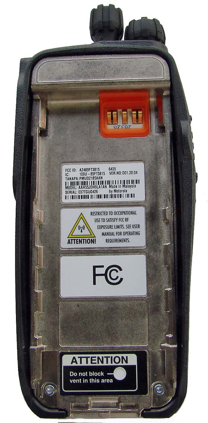
Click to zoom
Application Details
- Equipment Class
- TNF - Licensed Non-Broadcast Transmitter Held to Face
- Date of Grant
- Jun 12, 2007
- Application Purpose
- Original Equipment
- Date of Application
- Jun 12, 2007
- Equipment Note
- Portable 2-Way Radio
- Frequency Range
- 136.00000000 - 174.00000000
- Company
- Motorola Solutions, Inc.
- Country
- United States
Documents & Files
Document Text
Text extracted from the exhibit documents filed with the FCC. Open a document above to read the original.
Users Manual
Declaration of Conformity English ii Note: This equipment has been tested and found to comply with the limits for a Class B digital device, pursuant to part 15 of the FCC Rules. These limits are designed to provide reasonable protection against harmful interference in a residential installation. This equipment generates, uses and can radiate radio frequency energy and, if not installed and used in accordance with the instructions, may cause harmful interference to radio communications. However, there is no guarantee that interference will not occur in a particular installation. If this equipment does cause harmful interference to radio or television reception, which can be determined by turning the equipment off and on, the user is encouraged to tr y to correct the interference by one or more of the following measures: • Reorient or relocate the receiving antenna. • Increase the separation between the equipment and receiver. • Connect the equipment into an outlet on a circuit different from that to which the receiver is connected. • Consult the dealer or an experienced radio/TV technician for help. Contents English iii ContentsThis User Guide contains all the informatio n you need to use the MOTOTRBO XPR Series Portables.Declaration of Conformity . . . . . . . . . . . . . . . . . . . . . iImportant Safety Info rmation . . . . . . . . . . . . . . . . . vii Product Safety and RF Exposure Compliance . . vii Computer Software Copyrights . . . . . . . . . . . . . . viiiGetting Started . . . . . . . . . . . . . . . . . . . . . . . . . . . . . . 1 How to Use This Guide . . . . . . . . . . . . . . . . . . . . . . . 1What Your Dealer/Sys tem Administrator Can Tell You . . . . . . . . . . . . . . . . . . . . . . . . . . . . . . 1 Preparing Your Radio for Use . . . . . . . . . . . . . . . . . . 2 Charging the Battery . . . . . . . . . . . . . . . . . . . . . . . . . 2Attaching the Battery . . . . . . . . . . . . . . . . . . . . . . . . . 2Attaching the Antenna . . . . . . . . . . . . . . . . . . . . . . . . 3Attaching the Belt Clip . . . . . . . . . . . . . . . . . . . . . . . . 3Attaching the Universal Connector Cover . . . . . . . . . 3Powering Up the Radio . . . . . . . . . . . . . . . . . . . . . . . 4Adjusting the Volume . . . . . . . . . . . . . . . . . . . . . . . . 4 Identifying Radio Controls . . . . . . . . . . . . . . . . . . . . 5 Radio Controls You Will Be Using . . . . . . . . . . . . . . 5Programmable Buttons . . . . . . . . . . . . . . . . . . . . . . . 6 Assignable Radio Functions . . . . . . . . . . . . . . . . . 6Assignable Settings or Utility Functions . . . . . . . . . 7 Accessing the Preprog rammed Functions . . . . . . . . 7 Using the Keypad . . . . . . . . . . . . . . . . . . . . . . . . . . . 8Push-To-Talk (PTT) Button . . . . . . . . . . . . . . . . . . . . 9Switching Between Analog and Digital Mode . . . . . . 9 Identifying Status Indicators . . . . . . . . . . . . . . . . . . 10 Display Icons . . . . . . . . . . . . . . . . . . . . . . . . . . . . . . 10Call Icons . . . . . . . . . . . . . . . . . . . . . . . . . . . . . . . . 11LED Indicator . . . . . . . . . . . . . . . . . . . . . . . . . . . . . 11Audio Tones . . . . . . . . . . . . . . . . . . . . . . . . . . . . . . 12 Making and Receiving Calls . . . . . . . . . . . . . . . . . . 12 Selecting a Zone . . . . . . . . . . . . . . . . . . . . . . . . . . . 12Selecting a Radio Channel, Subscriber ID, or Group ID . . . . . . . . . . . . . . . . . . . . . . . . . . . . . . 13 Receiving and Resp onding to a Radio Call . . . . . . 13 Receiving and Responding to a Group Call . . . . . 14Receiving and Resp onding to a Private Call . . . 14 Contents English iv Receiving an All Call . . . . . . . . . . . . . . . . . . . . . . 15 Making a Radio Call . . . . . . . . . . . . . . . . . . . . . . . . 16 Making a Voice Call with the Channel Selector Knob . . . . . . . . . . . . . . . . . . . . . . . . . . . 16 Making a Group Call . . . . . . . . . . . . . . . . . . . . 16Making a Private Call . . . . . . . . . . . . . . . . . . . 17Making an All Call . . . . . . . . . . . . . . . . . . . . . . 17 Making a Group or Private Call with the One Touch Call Button . . . . . . . . . . . . . . . . . . . . 17 Talkaround . . . . . . . . . . . . . . . . . . . . . . . . . . . . . . . 18Monitoring Features . . . . . . . . . . . . . . . . . . . . . . . . 19 Monitoring a Channel . . . . . . . . . . . . . . . . . . . . . 19Permanent Monitor . . . . . . . . . . . . . . . . . . . . . . . 19 Advanced Features . . . . . . . . . . . . . . . . . . . . . . . . . 20 Radio Check . . . . . . . . . . . . . . . . . . . . . . . . . . . . . 20 Sending a Radio Check . . . . . . . . . . . . . . . . . . . 20 Remote Monitor . . . . . . . . . . . . . . . . . . . . . . . . . . . 21 Initiating Remote Monitor . . . . . . . . . . . . . . . . . . 21 Scan Lists . . . . . . . . . . . . . . . . . . . . . . . . . . . . . . . . 23 Viewing an Entry in the Scan List . . . . . . . . . . . . 23Editing the Scan List . . . . . . . . . . . . . . . . . . . . . . 23 Adding a New Entry to the Scan List . . . . . . . . 23Deleting an Entry from the Scan List . . . . . . . . 24 Setting and Editing Priority for an Entry in the Scan List . . . . . . . . . . . . . . . . . . . . . . . . 24 Scan . . . . . . . . . . . . . . . . . . . . . . . . . . . . . . . . . . . . 25 Starting and Stopping Scan . . . . . . . . . . . . . . . . 25Responding to a Transmission During a Scan . . 26Deleting a Nuisance Channel . . . . . . . . . . . . . . . 26Restoring a Nuisance Channel . . . . . . . . . . . . . . 26 Contacts Settings . . . . . . . . . . . . . . . . . . . . . . . . . . 27 Making a Group Call from Contacts . . . . . . . . . . 27Making a Private Call from Contacts . . . . . . . . . 28Making a Private Call by Alias Search . . . . . . . . 28 Call Indicator Settings . . . . . . . . . . . . . . . . . . . . . . 29 Activating and Deactivating Call Ringers for Private Calls . . . . . . . . . . . . . . . . . . …
Text truncated - open the document above for the full version.
Users Manual
English Product Safety and RF Energy Exposure Booklet for Portable Two-Way Radios The information provided in this document supersedes the general safety information contained in user guides published prior to February 2002. BEFORE USING THIS RADIO, READ THIS BOOKLET WHICH CONTAINS IMPORTANT OPERATING INSTRUCTIONS FOR SAFE USAGE AND RF ENERGY AWARENESS AND CONTROL INFORMATION AND OPERATIONAL INSTRUCTIONS FOR COMPLIANCE WITH RF ENERGY EXPOSURE LIMITS IN APPLICABLE NATIONAL AND INTERNATIONAL STANDARDS. ALSO READ THE OPERATIONAL INSTRUCTIONS FOR SAFE USAGE. FOR RADIOS THAT HAVE BEEN APPROVED AS INTRINSICALLY SAFE, READ THE INSTRUCTIONS AND INFORMATION ON INTRINSIC SAFETY ON PAGE 10 OF THIS BOOKLET. ! C a u t i o n © Motorola, Inc. 2004 8000 W. Sunrise Blvd., Ft. Lauderdale, FL 33322 68P81095C98 68P81095C98-C 95C98-C.book Page 1 Wednesday, October 27, 2004 11:59 AM 2 English RF Energy Exposure Awareness and Control Information and Operational Instructions for Occupational Use NOTICE: This radio is intended for use in occupational/controlled conditions where users have full knowledge of their exposure and can exercise control over their exposure to meet the occupational limits in FCC and International standards. This radio device is NOT authorized for general population consumer use. This two-way radio uses electromagnetic energy in the radio frequency (RF) spectrum to provide communications between two or more users over a distance. It uses radio frequency (RF) energy or radio waves to send and receive calls. RF energy is one form of electromagnetic energy. Other forms include, but are not limited to, sunlight and x-rays. RF energy, however, should not be confused with these other forms of electromagnetic energy, which when used improperly, can cause biological damage. Very high levels of x-rays, for example, can damage tissues and genetic material. Experts in science, engineering, medicine, health, and industry work with organizations to develop standards for safe exposure to RF energy. These standards provide recommended levels of RF exposure for both workers and the general public. These recommended RF exposure levels include substantial margins of protection. All Motorola two-way radios are designed, manufactured, and tested to ensure they meet government-established RF exposure levels. In addition, manufacturers also recommend specific operating instructions to users of two-way radios. These instructions are important because they inform users about RF energy exposure and provide simple procedures on how to control it. 95C98-C.book Page 2 Wednesday, October 27, 2004 11:59 AM 3 English Please refer to the following websites for more information on what RF energy exposure is and how to control your exposure to assure compliance with established RF exposure limits: http://www.fcc.gov/oet/rfsafety/rf-faqs.html http://www.osha.gov/SLTC/radiofrequencyradiation/index.html Federal Communication Commission (FCC) Regulations The FCC rules require manufacturers to comply with the FCC RF energy exposure limits for portable two-way radios before they can be marketed in the U.S. When two-way radios are used as a consequence of employment, the FCC requires users to be fully aware of and able to control their exposure to meet occupational requirements. Exposure awareness can be facilitated by the use of a product label directing users to specific user awareness information. Your Motorola two-way radio has a RF Exposure Product Label. Also, your Motorola user manual, or separate safety booklet includes information and operating instructions required to control your RF exposure and to satisfy compliance requirements. Compliance with RF Exposure Standards Your Motorola two-way radio is designed and tested to comply with a number of national and International standards and guidelines (listed below) for human exposure to radio frequency electromagnetic energy. This radio complies with the IEEE (FCC) and ICNIRP exposure limits for occupational/controlled RF exposure environments at operating duty factors of up to 50% talk-50% listen and is authorized by the FCC for occupational use only. In terms of measuring RF energy for compliance with these exposure guidelines, your radio generates measurable RF energy only while it is transmitting (during talking), not when it is receiving (listening) or in standby mode. NOTE:The approved batteries, supplied with this radio, are rated for a 5-5-90 duty factor (5% talk-5% listen-90% standby) even though this radio complies with FCC occupational exposure limits and may operate at duty factors of up to 50% talk. 95C98-C.book Page 3 Wednesday, October 27, 2004 11:59 AM 4 English Your Motorola two-way radio complies with the following RF energy exposure standards and guidelines: • United States Federal Communications Commission, Code of Federal Regulations; 47CFR part 2 sub-part J • American National Standards Institute (ANSI) / Institute of Electrical and Electronic Engineers (IEEE) C95. 1-1992 • Institute of Electrical and Electronic Engineers (IEEE) C95.1-1999 Edition • International Commission on Non-Ionizing Radiation Protection (ICNIRP) 1998 • Ministry of Health (Canada) Safety Code 6. Limits of Human Exposure to Radiofrequency Electromagnetic Fields in the Frequency Range from 3 kHz to 300 GHz, 1999 • Australian Communications Authority Radiocommunications (Electromagnetic Radiation – Human Exposure) Standard, 2003 • ANATEL ANNEX to Resolution No. 303 of July 2, 2002 "Regulation of limitation of exposure to electrical, magnetic and electromagnetic fields in the radio frequency range between 9 KHz and 300 GHz" and "Attachment to resolution # 303 from July 2, 2002" RF Exposure Compliance and Control Guidelines and Operating Instructions To control your exposure and ensure compliance with the occupational/controlled environment exposure limits, always adhere to the following procedures. Guidelines: • Do not remove the RF Exposure Label from the device. • User awareness i…
Text truncated - open the document above for the full version.
Cover Letter(s)
EXHIBIT 13B SHEET 1 FCC ID: AZ489FT3815 REQUEST FOR CONFIDENTIALITY Date: 8 th June 2007 Authorization & Evaluation Division Federal Communications Commission Laboratory 7435 Oakland Mills Road Columbia, MD 21046 SUBJECT: APPLICATION FOR CERTIFICATION OF TRANSMITTER WITH FCC ID: AZ489FT3815 Dear Sir / Madam, Motorola is requesting that Exhibit 4 (Circuit Descriptions), Exhibit 5 (Schematic Diagrams), Exhibit 10 (Parts List and Tune-Up Procedures), and Exhibit 12 (Operational Description) not be made routinely available for public inspection. Motorola considers the information in these exhibits to be classified as trade secrets, pursuant to 47 CFR Section 0.457(d) and Section 552(b)(4) of the Freedom of Information Act. We are also requesting that the FCC mark Exhibit 3 (External Photos), Exhibit 8 and Exhibit 9 (Internal Photos) as Temporary Confidentiality as outlined in Public Notice DA 04-1705, dated June 15, 2004. This provision will give Motorola temporary confidentiality prior to product launch. Please mark Exhibits 4, 5, 10, and 12 as “Confidential” And Exhibit 3, 8 and 9 as “Temporary Confidential”. Please contact me if you require any additional information. Sincerely, /s/ Mike Ramnath (signed) Mike Ramnath Manager, Regulatory Compliance Email: [email protected]
Cover Letter(s)
EXHIBIT 13A SHEET 1 FCC ID: AZ489FT3815 Date: 8 th June 2007 Authorization & Evaluation Division Federal Communications Commission Laboratory 7435 Oakland Mills Road Columbia, MD 21046 SUBJECT: APPLICATION FOR CERTIFICATION OF TRANSMITTER WITH FCC ID: AZ489FT3815; MOTOTRBO VHF Range 1 (136–174 MHz), 1–5 Watts Rated Variable Power, Max Power 6 Watts. Dear Sir / Madam, Motorola Inc., 8000 West Sunrise Blvd., Fort Lauderdale, Florida, herein submits application for Certification of the equipment identified by FCC ID number AZ489FT3815. This transmitter is primarily intended for use in a portable radio application with capabilities for conventional communications with a conducted transmit power which is adjustable from 1.0 Watts (+30 dBm) to 6.0 Watts (+37.78dBm). This is a VHF portable two-way radio that operates using APCO 25(C4FM) digital voice frequency modulation (FM) incorporating traditional simplex transmission protocol (50% Duty Cycle) and may be marketed to and used by employees for occupational operations, such as Federal and Public Safety agencies, e.g. police, fire and emergency medical, etc. The subject transmitter complies with CFR Title 47, Section 90.203, in that the operator cannot directly program the transmit frequencies using only the normally accessible external controls of the unit. Enclosed is a complete Certification Application. Please contact me if you require any additional information. Sincerely, /s/ Mike Ramnath (signed) Mike Ramnath Manager, Regulatory Compliance Email: [email protected]
External Photos
Applicant: Motorola Inc. FCC ID: AZ489FT3815 EXHIBIT 3 SHEET 1 OF 4 EXHIBIT 3 EXTERNAL PHOTOGRAPHS - Pursuant to 47 CFR 2.1033(c) 12 FIGURE 3-1: Front view of MOTOTRBO - Full display and keypad model Applicant: Motorola Inc. FCC ID: AZ489FT3815 EXHIBIT 3 SHEET 2 OF 4 FIGURE 3-2: Front view of MOTOTRBO - Plain model Applicant: Motorola Inc. FCC ID: AZ489FT3815 EXHIBIT 3 SHEET 3 OF 4 FIGURE 3-3: Back view of MOTOTRBO Applicant: Motorola Inc. FCC ID: AZ489FT3815 EXHIBIT 3 SHEET 4 OF 4 FIGURE 3-6: FCC and safety labels location of MOTOTRBO. FCC Label Location Safety Label
ID Label/Location Info
Applicant: Motorola Inc. FCC ID: AZ489FT3815 EXHIBIT 1 SHEET 1 OF 1 EXHIBIT 1 IDENTIFICATION LABEL - Pursuant to 47 CFR 2.925(a) & 2.1033(c) (11) EXHIBIT 1A - LABEL LOCATION A nameplate of the type presented below will be affixed to every transmitter. It will be placed on the bottom of the unit near the front. Shown below is a photo of the actual label affixed to the cast chassis of the transmitter. EXHIBIT 1B - LABEL TYPE The label is a paper polyester film laminate with a pressure sensitive adhesive backing. The adhesive is a permanent type acrylic with minimum peel strength of 40 oz/inch. Please note that Motorola complies with FCC Rule Part 2.925 (d) that the label is permanently affixed and is readily visible to the purchaser at the time of purchase. Figure 1-1: FCC Label EXHIBIT 1C - GENERAL INFORMATION 1. Application References: TIA/EIA-603B Land Mobile FM or PM Communications Equipment Measurement and Performance Standards Code of Federal Regulations Title 47, Part 2, Sec. 2.1033-2.1057, and Part 90, Section 90.210. 2. Data Submittal Procedure: Data is supplied in accordance with Part 2, Sub-part J of the Commission’s rules. The intended use of this transceiver includes applications covered in the Code of Federal Regulations Title 47, and Part 90. Maximum transmitter power shall not be adjustable by the user. 3. Applicable Reference • Reference Certification FCC ID: AZ489FT3815 • EIA/TIA-603 Land Mobile FM or PM Communications Equipment Measurement and Performance Standards. • FCC Federal Regulations Part 47 Sec. 2.1033-2.1057 • FCC Federal Regulations Part 90 Sec.90.210
Internal Photos
Applicant: Motorola Inc. FCC ID: AZ489FT3815 EXHIBIT 9 SHEET 1 OF 6 EXHIBIT 9 INTERNAL PHOTOGRAPHS – PURSUANT 47 CFR 2.1033 ( C) 12 FIGURE 3-1: MOTOTRBO complete internal open up view. Applicant: Motorola Inc. FCC ID: AZ489FT3815 EXHIBIT 9 SHEET 2 OF 6 FIGURE 3-2: MOTOTRBO with option board. Applicant: Motorola Inc. FCC ID: AZ489FT3815 EXHIBIT 9 SHEET 3 OF 6 FIGURE 3-3: MOTOTRBO with LCD and metal bracket detached. Applicant: Motorola Inc. FCC ID: AZ489FT3815 EXHIBIT 9 SHEET 4 OF 6 FIGURE 3-7: MOTOTRBO board with clip-shield detached. Applicant: Motorola Inc. FCC ID: AZ489FT3815 EXHIBIT 9 SHEET 5 OF 6 FIGURE 3-8: MOTOTRBO bottom view board without GPS. FIGURE 3-9: MOTOTRBO bottom view board with GPS. Applicant: Motorola Inc. FCC ID: AZ489FT3815 EXHIBIT 9 SHEET 6 OF 6 FIGURE 3-10: MOTOTRBO board top view.
RF Exposure Info
MOTOROLA, INC. FCC ID: AZ489FT3815 RF EXPOSURE The output power of this device is less than 7 watts – therefore SAR is not required.
Test Report
Applicant: Motorola Inc. FCC ID: AZ489FT3815 EXHIBIT 6 SHEET 1 OF 45 EXHIBIT 6 INDEX OF SUBMITTED MEASURED DATA This exhibit contains the measured data for this equipment as follows: EXHIBIT 6A – RF Power Output (Table) EXHIBIT 6B – Audio Frequency Response (2 Graphs) 6B-1: 12.5 kHz Channel Spacing 6B-2: 25 kHz Channel Spacing EXHIBIT 6C – Audio Low Pass Filter Response (2 Graphs) 6C-1: 12.5 kHz Channel Spacing 6C-2: 25 kHz Channel Spacing EXHIBIT 6D – Modulation Limiting (6 Graphs) 6D-1: 12.5 kHz Channel Spacing, Carrier Squelch (CSQ) Mode 6D-2: 12.5 kHz Channel Spacing, Tone Private Line (TPL) Mode 6D-3: 12.5 kHz Channel Spacing, Digital Private Line (DPL) Mode 6D-4: 25 kHz Channel Spacing, Carrier Squelch (CSQ) Mode 6D-5: 25 kHz Channel Spacing, Tone Private Line (TPL) Mode 6D-6: 25 kHz Channel Spacing, Digital Private Line (DPL) Mode EXHIBIT 6E – Occupied Bandwidth (20 Spectrum Analyzer Plots) 6E-1: 12.5 kHz Channel Spacing, 2500 Hz Audio Modulation Only 6E-2: 12.5 kHz Channel Spacing, 2500 Hz Audio and PL Tone Modulation 6E-3: 12.5 kHz Channel Spacing, 2500 Hz Audio and DPL Tone Modulation 6E-4: 12.5 kHz Channel Spacing, DTMF Modulation Only 6E-5: 12.5 kHz Channel Spacing, DTMF and PL Tone Modulation 6E-6: 12.5 kHz Channel Spacing, DTMF and DPL Tone Modulation 6E-7: 12.5 kHz Channel Spacing, 2000/3000 Hz FSK Data Modulation Only 6E-8: 12.5 kHz Channel Spacing, 2000/3000 Hz FSK Data and PL Tone Modulation 6E-9: 12.5 kHz Channel Spacing, 2000/3000 Hz FSK Data and DPL Tone Modulation 6E-10: 25 kHz Channel Spacing, 2500 Hz Audio Modulation Only 6E-11: 25 kHz Channel Spacing, 2500 Hz Audio and PL Tone Modulation 6E-12: 25 kHz Channel Spacing, 2500 Hz Audio and DPL Tone Modulation 6E-13: 25 kHz Channel Spacing, DTMF Modulation Only 6E-14: 25 kHz Channel Spacing, DTMF and PL Tone Modulation 6E-15: 25 kHz Channel Spacing, DTMF and DPL Tone Modulation 6E-16: 25 kHz Channel Spacing, 2000/3000 Hz FSK Data Modulation Only 6E-17: 25 kHz Channel Spacing, 2000/3000 Hz FSK Data and PL Tone Modulation 6E-18: 25 kHz Channel Spacing, 2000/3000 Hz FSK Data and DPL Tone Modulation 6E-19: O.153 Test Pattern 4FSK Voice and Data Modulation 6E-20: O.153 Test Pattern 4FSK Data Modulation Only EXHIBIT 6F – Conducted Spurious Emissions (16 Graphs) 6F-1: 1.2 Watts Harmonic of Carrier 136.0125 MHz, 12.5 kHz Channel Spacing 6F-2: 1.2 Watts Harmonic of Carrier 150.0125 MHz, 12.5 kHz Channel Spacing 6F-3: 1.2 Watts Harmonic of Carrier 162.0125 MHz, 12.5 kHz Channel Spacing 6F-4: 1.2 Watts Harmonic of Carrier 173.9875 MHz, 12.5 kHz Channel Spacing 6F-5: 6 Watts Harmonic of Carrier 136.0125 MHz, 12.5 kHz Channel Spacing 6F-6: 6 Watts Harmonic of Carrier 150.0125 MHz, 12.5 kHz Channel Spacing 6F-7: 6 Watts Harmonic of Carrier 162.0125 MHz, 12.5 kHz Channel Spacing 6F-8: 6 Watts Harmonic of Carrier 173.9875 MHz, 12.5 kHz Channel Spacing 6F-9: 1.2 Watts Harmonic of Carrier 136.0125 MHz, 25 kHz Channel Spacing 6F-10: 1.2 Watts Harmonic of Carrier 150.0125 MHz, 25 kHz Channel Spacing 6F-11: 1.2 Watts Harmonic of Carrier 162.0125 MHz, 25 kHz Channel Spacing 6F-12: 1.2 Watts Harmonic of Carrier 173.9875 MHz, 25 kHz Channel Spacing Applicant: Motorola Inc. FCC ID: AZ489FT3815 EXHIBIT 6 SHEET 2 OF 45 6F-13: 6 Watts Harmonic of Carrier 136.0125 MHz, 25 kHz Channel Spacing 6F-14: 6 Watts Harmonic of Carrier 150.0125 MHz, 25 kHz Channel Spacing 6F-15: 6 Watts Harmonic of Carrier 162.0125 MHz, 25 kHz Channel Spacing 6F-16: 6 Watts Harmonic of Carrier 173.9875 MHz, 25 kHz Channel Spacing EXHIBIT 6G – Radiated Spurious Emissions (12 Graphs) 6G-1: 1.2 Watts, 136.0125 MHz, 12.5 kHz Channel Spacing 6G-2: 1.2 Watts, 155.0125 MHz, 12.5 kHz Channel Spacing 6G-3: 1.2 Watts, 173.9875 MHz, 12.5 kHz Channel Spacing 6G-4: 1.2 Watts, 136.0125 MHz, 25 kHz Channel Spacing 6G-5: 1.2 Watts, 155.0125 MHz, 25 kHz Channel Spacing 6G-6: 1.2 Watts, 173.9875 MHz, 25 kHz Channel Spacing 6G-7: 6 Watts, 136.0125 MHz, 12.5 kHz Channel Spacing 6G-8: 6 Watts, 155.0125 MHz, 12.5 kHz Channel Spacing 6G-9: 6 Watts, 173.9875 MHz, 12.5 kHz Channel Spacing 6G-10: 6 Watts, 136.0125 MHz, 25 kHz Channel Spacing 6G-11: 6 Watts, 155.0125 MHz, 25 kHz Channel Spacing 6G-12: 6 Watts, 173.9875 MHz, 25 kHz Channel Spacing EXHIBIT 6H – Frequency Stability (4 Graphs) 6H-1 – 1.5ppm Frequency Stability vs. Temperature 6H-2 – 1.5ppm Frequency Stability vs. Voltage 6H-3 – 0.5ppm Frequency Stability vs. Temperature 6H-4 – 0.5ppm Frequency Stability vs. Voltage EXHIBIT 6I – Transient Frequency Behavior (16 Graphs) 6I-1-1: 1.5ppm, 1.2 Watt, 12.5 kHz Key-Up Attack Time 6I-1-2: 1.5ppm, 1.2 Watt, 12.5 kHz De-Key Decay Time 6I-1-3: 1.5ppm, 1.2 Watt, 25 kHz Key-Up Attack Time 6I-1-4: 1.5ppm, 1.2 Watt, 25 kHz De-Key Decay Time 6I-1-5: 1.5ppm, 6 Watts, 12.5 kHz Key-Up Attack Time 6I-1-6: 1.5ppm, 6 Watts, 12.5 kHz De-Key Decay Time 6I-1-7: 1.5ppm, 6 Watts, 25 kHz Key-Up Attack Time 6I-1-8: 1.5ppm, 6 Watts, 25 kHz De-Key Decay Time 6I-1-9: 0.5ppm, 1.2 Watt, 12.5 kHz Key-Up Attack Time 6I-1-10: 0.5ppm, 1.2 Watt, 12.5 kHz De-Key Decay Time 6I-1-11: 0.5ppm, 1.2 Watt, 25 kHz Key-Up Attack Time 6I-1-12: 0.5ppm, 1.2 Watt, 25 kHz De-Key Decay Time 6I-1-13: 0.5ppm, 6 Watts, 12.5 kHz Key-Up Attack Time 6I-1-14: 0.5ppm, 6 Watts, 12.5 kHz De-Key Decay Time 6I-1-15: 0.5ppm, 6 Watts, 25 kHz Key-Up Attack Time 6I-1-16: 0.5ppm, 6Watts, 25 kHz De-Key Decay Time EXHIBIT 6J – Power Line Conducted Spurious Emissions 6J-1 – Radio off Line/Neutral 6J-2 – Radio on Rx Line/Neutral 6J-3 – Radio on Tx Line/Neutral Applicant: Motorola Inc. FCC ID: AZ489FT3815 EXHIBIT 6 SHEET 3 OF 45 EXHIBIT 6A RF Conducted Power Output Data -- Pursuant 47 CFR 2.1046(a), 2.1033(c)(6), 2.1033(c)(7) and 2.1033(c)(8) The RF power output was measured with the indicated voltage applied to and current into the final RF amplifying device At maximum output power setting, Frequency 136.0125 MHz: Output RF power 5.98 Watts DC Voltage 7.50 Volts DC Current 1.96 Amps DC Input Power 14.70 Watts At minimum output power setting, Frequency 136.0125 MH…
Text truncated - open the document above for the full version.
Test Report
Applicant: Motorola Inc. FCC ID: AZ489FT3815 EXHIBIT 7 SHEET 1 OF 5 EXHIBIT 7 MEASUREMENT PROCEDURES USED FOR SUBMITTED DATA EXHIBIT 7A - RF Output Power vs. DC Power Input - Pursuant to 47 CFR 2.1046 Conducted power is measured in accordance with TIA/EIA-603 section 2.2.1.2. The transmitter under test is connected to an HP 438A Power Meter using the forward port of a directional coupler and a 20 dB pad. Appropriate calibration offsets, derived from a traceable RF attenuator, which has been precision characterized by an outside testing laboratory, are entered into the wattmeter to calibrate for the use of the coupler. The transmitter is operated under normal conditions at the specified nominal DC input voltage. The DC supply path to the final stage only (or to the RF power amplifier module, if the final stage only is not accessible) is interrupted to allow insertion of a DC ammeter in series with the DC supply. The DC voltage drop of the ammeter is negligible. A DC voltmeter is used to measure the DC voltage applied to the final stage. The DC input power to the final stage (in watts) is computed as the product of the DC current (in amperes) times the DC voltage (in volts). This measurement is performed at the lowest, the middle, and the highest operating frequencies of the operating bandwidth of the equipment. The calibration of the power meter, detector, and attenuator pads is verified on an annual basis. Other power measurement systems that may be used are correlated with this calibrated reference system before measurements are performed, and calibration factors are adjusted as necessary to obtain precise correlation. EXHIBIT 7B - Transmit Audio Frequency Response – Pursuant to 47 CFR 2.1047 (a) The transmitter output is monitored with an HP8901B modulation analyzer, whose FM demodulator output is fed to an HP8903B audio analyzer. De-emphasis or filtering within the test equipment is not used. An audio oscillator signal, derived from the HP8903B Audio Analyzer, is connected to the microphone audio input of the transmitter. At a frequency of 1 kHz, the level is adjusted to obtain 20% of full system deviation, to ensure that limiting does not occur at any frequency in the range of 300 Hz – 3000 Hz. A constant input level is then maintained and the oscillator frequency is varied between the ranges of 300 Hz to 3000 Hz. The frequency response is plotted, using a reference of 0 dB at 1 kHz. EXHIBIT 7C - Transmit Audio Post Limiter Low Pass Filter Response – Pursuant to 47 CFR 2.1047 (a) The audio oscillator portion of an HP8903B audio analyzer is connected to the input of the post limiter low pass filter. The oscillator is adjusted, at 1000 Hz and level 16 dB greater than that required to produce standard test modulation. The output of the low pass filter is measured with an Agilent 35670A dynamic signal analyzer. The response is swept between the limits of 1000 Hz - 30000 Hz. Oscillator level is chosen to be as high as possible and that will not cause limiting at any frequency, and maintaining a constant input level versus frequency. EXHIBIT 7D – Modulation Limiting Characteristic – Pursuant to 47 CFR 2.1047 (d) An audio oscillator is connected to the microphone audio input. The transmitter output is monitored with an HP8901B modulation analyzer. The flat frequency response FM demodulator output of the HP8901B is fed to an HP8903B audio analyzer. The 20 kHz low pass filter of the modulation analyzer is used to reduce the level of residual high frequency noise. The oscillator level is adjusted, at 1 kHz, to obtain 60% of full system deviation. The oscillator level is then varied over a range of +/-20dB in 5 dB increments, and the resulting deviation is plotted. This measurement is repeated at 300 Hz and 3 kHz. The above procedure is performed three times, for conditions with Tone Private Line, Digital Private Line, and Carrier Squelch Mode (without sub-audible signaling). Applicant: Motorola Inc. FCC ID: AZ489FT3815 EXHIBIT 7 SHEET 2 OF 5 EXHIBIT 7E - Occupied Bandwidth - Pursuant to 47 CFR 2.1049 (c) (1) Procedure for Occupied Bandwidth Measurement for Voice Transmission The transmitter is connected, via a suitable attenuator, to the Agilent E4445B Spectrum Analyzer. The spectrum analyzer settings for the reference calibration are in accordance with 47 CFR 90.210 (d) (4). The unmodulated carrier’s emission spectrum is captured on the spectrum analyzer and then used to establish a 0 dB reference plot for exhibits. The HP 8903B audio source is connected to the microphone audio input of the transmitter. The audio source frequency is set to 2500 Hz and the amplitude is adjusted to a level 16 dB above that required to produce 50% of full system deviation at the frequency of maximum response of the audio modulation circuit, in accordance with 47 CFR Part 2.1049(c)(1). The spectrum analyzer settings are adjusted in accordance with 47 CFR 90.210(d)(4) and the analyzer is swept to record the resultant emission levels using the appropriate emission mask. This measurement is repeated with Tone Private Line (TPL) sub-audible signaling and audio by adding a 250.3 Hz TPL tone at 15% full system deviation with the previously defined 2500 Hz tone. The amplitude of the modulating signal is adjusted so that the total deviation, which includes the TPL deviation, is the full system deviation. An additional measurement is made with Digital Private Line (DPL) sub-audible signaling and audio by adding a DPL code 131 at 15% full system deviation with the previously defined 2500 Hz tone. The amplitude of the modulating signal is adjusted so that the total deviation, which includes the DPL deviation, is the full system deviation. Procedure for Occupied Bandwidth Measurement for 2000/3000 Hz FSK Data The transmitter is connected, via a suitable attenuator, to the Agilent E4445B Spectrum Analyzer. The spectrum analyzer settings for the reference calibration are in accordance with 47 CFR 90.210 (d) (4). The unmodulate…
Text truncated - open the document above for the full version.
Contact Information
Applicant
Arine Lee(Certification Manager)
Test Firm
MotorolaWilliam Elliott
Technical Specifications
| # | Rule Parts | Frequency Range | Power Output | Emission | Tolerance |
|---|---|---|---|---|---|
| 4 | 9 | 136 MHz - 174 MHz | 5 W | 7K60FXE | 1.5 ppm |
Other Applications from Motorola Solutions, Inc.

AZ489FT4980
Sep 08, 2026Portable two way radio
Equipment Class
TNF - Licensed Non-Broadcast Transmitter Held to FaceAZ489FT4981
Aug 14, 2026Handheld Portable - TANAPA BPR 45 400-470 MHZ 4W NKP
Equipment Class
TNF - Licensed Non-Broadcast Transmitter Held to Face
AZ489FT7187
Jul 13, 2026Portable 2-Way Radio with Bluetooth, Bluetooth LE, WIFI 2.4GHz, WIFI 5GHz, LTE
Equipment Class
DSS - Part 15 Spread Spectrum TransmitterAZ499FT6031
May 11, 2026Operation Critical Wireless Earpiece PTT
Equipment Class
DSS - Part 15 Spread Spectrum Transmitter
AZ499FT5879
Dec 19, 20252-way Portable Radio with BT, BTLE, WIFI, NFC and LTE
Equipment Class
DSS - Part 15 Spread Spectrum Transmitter