AZ489FT4827HAND HELD PORTABLE RADIO TO BE USED IN THE FAMILY
Motorola Solutions, Inc.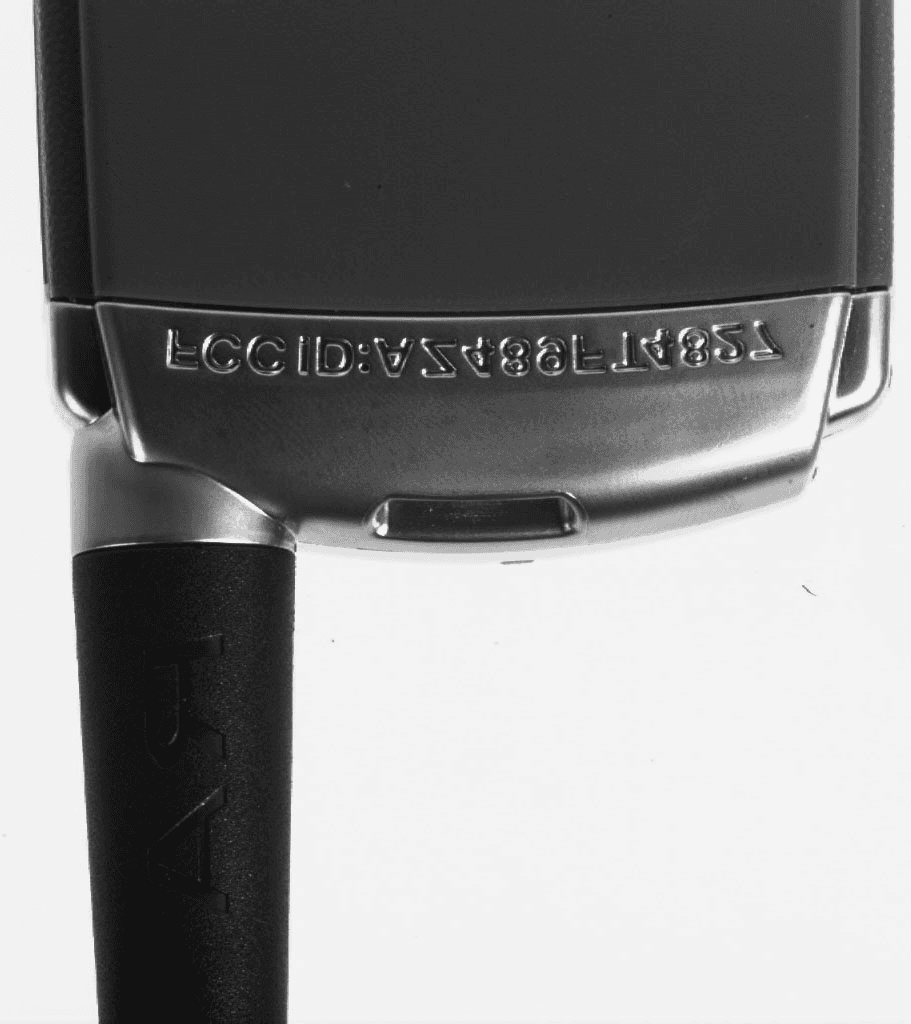
Click to zoom
Application Details
- Equipment Class
- FRF - Part 95 Family Radio Face Held Transmitter
- Date of Grant
- Sep 08, 1998
- Application Purpose
- Original Equipment
- Date of Application
- Jul 13, 1998
- Equipment Note
- HAND HELD PORTABLE RADIO TO BE USED IN THE FAMILY
- Frequency Range
- 462.56200000 - 467.71200000
- Company
- Motorola Solutions, Inc.
- Country
- United States
Documents & Files
Document Text
Text extracted from the exhibit documents filed with the FCC. Open a document above to read the original.
Users Manual
MOTOROLA INC FCC ID: AZ489FT4827 INSTRUCTION MANUAL X Preliminary Manual attached. Complete Manual attached. MOTOROLA INC FCC ID: AZ489FT4827 FP7 SLK Manual updates ver 0.1 TEXT REMOVALS: • Remove 3rd Note under To Set Channe l and Code regarding voice verification of settings. • Remove section on To Check Channel and Code . • Remove Be lt Clip FEATURE REVISIONS: After Let’s Talk About Your New Radio section, insert: Batteries Talk About SLK radios operate on either 3 AA alkaline batteries or a nickel metal hydride rechargeable battery pack, providing ???? • installation of both types to be noted Set The Channel And Code 1. Current channel is the large number on the LCD 2. P ress the Mode Button once, Channel indicator will appear on display. Use the Scroll Button to set new channel. 3. Press the Mode Button twice, current code (small number) will flash and radio beeps to indicate code change mode. 4. Use Scroll buttons to select a new code while number is flashing. Note: • To talk to other radios that do not have Interference Eliminator Codes, set your code to 0. • Radio automatically saves new code after 3 seconds. Lock Lock allows you to disable the radios primary settings so they can not be changed accidentally. To activate the Lock feature, press the Lock button. T he radio will beep and the Lock indicator will appear on the display. Only the P ush-T o-T alk (P T T ), Monitor, Light, and P ower buttons will remain active. • verify with software statement of work T he radio will beep if any disabled buttons are pressed. T o disable the Lock feature, press the Lock button again. The radio will beep and the Lock indicator will disappear. Light Talk About radios have a backlit display for usage in low-light conditions. To activate the Light, press the Light button. The light will turn on for five seconds. Pressing any other buttons on the radio will extend the period of time the display is backlit. Scan (TalkAbout SLK 200 only) MOTOROLA INC FCC ID: AZ489FT4827 Scan allows you to monitor the radio’s channels and code. When the radio detects channel activity on your radio’s code, it stops Scanning and locks in on the active channel. It allows you to listen and talk back automatically to the person transmitting without having to switch channels. The Scan function is user adjustable to monitor either selected Interference Eliminator Codes, all Interference Eliminator Codes, or all frequency usage. Note: • To communicate in selected Interference Eliminator Code Scan, your radio must be set to the same code as the other radio(s) in your group. If your radio is set to a different code, the Scan feature in this setting will not detect channel activity in your group. • When selected Scan type is all Interference Eliminator Codes, you will hear all channel activity except from radios without codes (CSQ). To hear uncoded radios, set the Scan type to setting 3 to hear all Interference Eliminator Codes and CSQ. To use Scan Feature 1. P ress the Scan button, radio will beep and flashing Scan indicator will appear on the display. 2. When the radio detects channel activity, you will hear the message. T he Scan indicator will stop flashing and the display will indicate the active channel. 3. Press Push-To-Talk button to talk back on the active channel. If channel activity ceases, the radio will return to Scan mode after three seconds. The display will return to the primary channel and the Scan indicator will begin to flash again. 4. In Scan, you will always transmit back to the channel visible on the display. 5. To turn off Scan, press the Scan button again. T he radio will beep and the Scan indicator will disappear. Notes: • In Scan, after you receive a message, the radio will remain on the active channel for three seconds before returning to Scan mode. T his will be indicated by the flashing Scan indicator. • In Scan, you will not be able to change the primary channel or code setting. To change the primary channel or code, first disable Scan operation by pressing the Scan button again. Call (TalkAbout SLK 200 only) The TalkAbout SLK 200 has 9 user-selectable call alert tones to alert other radio users to an incoming message and identify the transmitting radio. Other radio users will hear your call MOTOROLA INC FCC ID: AZ489FT4827 alert tone before receiving the incoming message. To use the call feature, press the Call Button before pressing the Push-To- Talk button. To change Call Tone 1. Press the Mode button four times, the call indicator will appear on the display and the call number will appear on the display. 2. Use the Scroll buttons to change the call tone. VOX REVISIONS: To Use VOX Feature: 1. Make sure the radio is off. 2. Open accessory jack cover and plug accessory’s connector into jack. 3. Turn radio on and lower volume before placing accessory on head or in ear. The VOX indicator will appear on the display to indicate that the VOX feature is active. 4. Press Monitor button while rotating Volume Dial to adjust volume to a comfortable listening level. 5. To transmit, speak into accessory microphone. To receive, stop talking. Note: T here will be a brief delay between when you start or stop talking and radio transmission. Reset to Push-To-Talk Mode: 1. Press Push-To-Talk button once. The VOX indicator will disappear. 2. To transmit, press Push-To-Talk button on radio. To receive, release the Push-To-Talk. 3. To return to VOX mode, turn the radio off, then on again. Note: The accessory jack cover is not detachable and should be closed when not in use. EXHIBIT 11
Attestation Statements
Motorola Inc FCC ID: AZ489FT4827 LIST OF EXHIBITS FCC DESCRIPTION EXHIBIT REFERENCE I. Certification of Data12.907 II. Identification label information22.983-(f) III. General Information3 1. Production Plans2.981-(c) 2. Application References2.1061 3. Data Submittal Procedure 4. Similar Applications IV. Description4 1. Technical Characteristics 2.983-(d)-1,2,3,4,5 2. Application V. Function of Semiconductor or52.983-(d)-6 other active devices VI. Circuit Diagrams62.983-(d)-7 VII. Tune-up Procedure72.983-(d)-9 VIII. Circuit Description2.983-(d)-10,11 1. Frequency Stabilizing8A 2. Modulation Limiting8B and Post Limiter Filter 3.Harmonic Suppression8C 4.Power Limiting8D IX. Measured Data2.983-(e) 1.Data Index9 2.RF Output-Data9A2.985 3.Modulation Characteristics2.987 a. Audio Response9B b. Low Pass Filter Response9C c. Modulation Limiting9D 4. Occupied Bandwidth9E2.989 5. Conducted Spurious Emissions 9F2.991 6. Radiated Spurious Emissions9G2.993 7. Frequency Stability (Temp & Supply Volt)9H2.995 X. Photograph(s)102.983-(g) XI. Instruction Manual112.983-D-8 XII. Measurement Procedure and Test Equip. Used122.999 Motorola Inc FCC ID: AZ489FT4827 STATEMENT OF CERTIFICATION The technical data supplied with this application, having been taken under my supervision is hereby duly certified. The following is a statement of my qualifications: 1) B.S.E.E. from the University of Miami. 2) M.S.E.E From Florida Atlantic University. 3) 1.5 years of Design and Development experience in the field of two-way radios. Name: Joe Zbib Date: July 13, 1998. Position: Electrical Dev. Engineer I hereby certify that the above application was prepared under my direction and that to the best of my knowledge and belief, the facts set forth in the application and accompanying technical data are true and correct: Name: Lorenzo Cruger Date: July 13, 1998. Position: Engineering Manager EXHIBIT 1 Motorola Inc FCC ID: AZ489FT4827 IDENTIFICATION LABEL LOCATION X See The Attached Photograph Or Sketch Back Of Radio Back Of Radio Under Belt Clip TYPE X The label is a paper polyester film laminate with a pressure sensitive adhesive backing. The adhesive is a permanent type acrylic with a minimum peel strength of 40 oz/ inch. The label is laser etched into the Urethane paint, exposing the Nickel plating on the Zamak casting substrate. Since no adhesive is required, the label is permanent and tamper-proof. (** - NOTE- The label attached below is a paper polyester film laminate, as described above. This is just for sample purposes, as the actual label is laser etched into the casting) MARKINGS (TEXT) X See The Attached Photograph Label Attached Below. See Attached Drawing. EXHIBIT 2 Motorola Inc FCC ID: AZ489FT4827 GENERAL INFORMATION I.Production Plans -- Pursuant 2.981 (c) Quantity production is planned II.Application References -- Pursuant 2.1061 Reference is made to the following Motorola "Application References" 1. Portable Products and their application. 2. Portable Products Transmitter Modulations Methods. 3. Boynton Beach Antenna Range. III.Data Submittal Procedure: Data is supplied in accordance with Part 2, Sub-part J of the Commissions’ rules. IV.Similar, currently Type Accepted Transmitter, FCC ID: ABZ99FT4070. EXHIBIT 3 Motorola Inc FCC ID: AZ489FT4827 DESCRIPTION I.Transmitter Technical Characteristics -- Pursuant 2.983 (d) A. RF Power Output0.5 Watt B. Frequency Range 462.5625 - 467.7125 MHz C. Frequency Stability 0.00025 % D. Emissions 11K0F3E (see General Info. ) E. Spurious Emissions 49.02 dBc F. DC Voltage and Current into 3.6 Nicad - 4.5 Alkaline Volts the RF amplifier 504 mAmp II.Transmitter Application This transmitter is primarily intended for use in a hand-held two-way portable radio. The radio is characterized by the following features, options and accessories. A. Power Supply Available 1. NiCad Battery X , Mercury Battery , Alkaline Battery X , AC , Lead Acid Battery , Nickel Metal Hydride . B. Antenna Available 1. Helical X , Telescopic , Whip X , Dipole . C. Squelch Types Available 1. Carrier Squelch X . 2. Tone "Private Line" X . 3. Digital "Private Line" . D. Microphone - Control 1. Handset/Palm Microphone X . 2. 600 Ohm wireline control . E. Maximum Transmit Channel Capability 14 . F. Housing The transmitter will be housed in the housing shown in the accompanying photographs. G. Other Options 1. Single Tone Encoder X 2. Multiple Single Tone Encoder N/A 3. Touch Code Encoder N/A 4. Unit ID Encoder N/A 5. EMS Telemetry Encoder N/A 6. Time out Timer X 7. Voice EncryptionN/A 8. Digital Signaling N/A 9. Sel-Call Decode N/A 10. Trunking N/A EXHIBIT 4
Block Diagram
MOTOROLA INC FCC ID: AZ489FT4827 CIRCUIT DESCRIPTION A general description of the overall circuit is not covered in an instruction manual. This section provides the description of circuits required by subpart 2.983 of the Commissions’ Rules. Circuits not described in the manual are covered in this exhibit. The following are included: 1. Means for Frequency Stabilization8A 2. Means for Modulation Limiting8B and Low Pass Filter* 3. Means for Harmonic Suppression8C 4. Means for Limiting Power*8D * From currently Type Accepted Transmitter FCC ID: ABZ99FT4070. EXHIBIT 8 MOTOROLA INC FCC ID: AZ489FT4827 CARRIER FREQUENCY GENERATION AND STABILIZATION CIRCUIT DESCRIPTION: The carrier frequency is generated using a fractional-N frequency synthesizer inside the ULTZif(U801). This consist of a phase-locked loop circuit with a voltage controlled oscillator (VCO) whose output is fed back to a programmable divider chain. The divide ratios are determined from information stored in the microcomputer and bussed to the synthesizer via a microcomputer. The microcomputer extracts the data for the division ratios as determined by the system select switch or by loading data stored in the memory ICs. Using a time averaged algorithm a combination of divide ratios are used so that the reference frequency can be a much higher value than the value of the frequency resolution. Modulation occurs by a combination of directly coupling the modulation signal to the low pass filter in the loop and by processing the digitized analog modulation signal to alter the divider values. A temperature compensated crystal oscillator at 16.8 MHz and stable to 2.5 parts per million over temperature extremes is used for the frequency reference. The 16.8 MHz reference is further divided into one of three reference frequencies which is compared to the divided down VCO output in a phase detector which in turn provides a DC steering voltage back to the VCO. EXHIBIT 8A MOTOROLA INC FCC ID: AZ489FT4827 MODULATION LIMITING AND LOW PASS FILTER CIRCUIT DESCRIPTION The pre-emphasis modulation limiting and low pass filtering of this transmitter are in integrated circuit form on the Audio/Signaling Filter section of the ULTZif(U801). Audio from the microphone initially enters the ULTZif(U801) where it is amplified, filtered and pre-emphasized. The limited, filtered audio is then fed through digitally programmable attenuators to the modulation port on the synthesizer module. EXHIBIT 8B MOTOROLA INC FCC ID: AZ489FT4827 HARMONIC SUPPRESSION CIRCUIT CIRCUIT DESCRIPTION: Attenuation for harmonics is provided by the Harmonic Filter after the Antenna Switch. The Harmonic Filter is a fifth order Low Pass Chebyshev with 0.1 dB of ripple composed of C104, L102, C105, L103, and C106. For Circuit Diagram refer to the Schematic in Exhibit 6. (100- Harmonic Filter) EXHIBIT 8C MOTOROLA INC FCC ID: AZ489FT4827 MEANS FOR LIMITING POWER CIRCUIT DESCRIPTION The transmit power Amplifier is an RF IC Chip amplifier with a specified maximum output of 0.5 Watts. An antenna switch(SW-391) controls the RF signal flow. In transmit mode, the RF signal flow is directed to the Harmonic filter. The output of the harmonic filter is connected to a helical antenna. The antenna is permanently attached to the radio and cannot be removed. For Circuit Diagram refer to the Schematic in Exhibit 6. (500- Tx PA) EXHIBIT 8D
Cover Letter(s)
FCC ID:AZ489FT4827 ______________________________________________________________________________ Radio Products Group 8000 West Sunrise Boulevard, Fort Lauderdale, Florida 33322. (954) 723-5000 Date: July 14 ,1998 Authorization & Evaluation Division. Federal Communications Commission Laboratory. 7435 Oakland Mills Road. Columbia, MD 21046. Att: George Tannahill, Frank Coperich Subject: Application for Type Acceptance of Transmitter with FCC ID: AZ489FT4827 Gentlemen: Motorola Inc. 8000 W Sunrise Boulevard, Fort Lauderdale, Florida, herein submits application for type acceptance of the subject transmitter. This transmitter is primarily intended for use in the Family Radio Service (FRS) with capabilities for clear communications with transmit power of 0.5Watt or 27 dBm output power. Per Exhibit 9C, Post Limiter Response vs. Frequency, the radio does not meet the FCC specifications. The response is limited to transmitter Hum and Noise performance. We cannot accurately measure the modulation limiting circuitry between the modulating limiter and the modulating stage because the circuitry is embedded in the U801-ULT Zif integrated circuit (IC) with no access for taking measurement data. The circuits in the FCC ID:ABZ99FT4070 are packaged in separate IC’s and are easily accessible for measurements. However, for this submission, these identical circuits were combined and embedded into the U801- ULT Zif IC where there is no access for data measurements. We are attaching a copy of the Low Pass Filter Response (see file attached) for FCC ID: ABZ99FT4070 to show that the response would be identical if we were able to measure it. The subject transmitter complies with Section 90.203 of the rules in that the operator cannot directly program transmit frequencies using only the unit's normally accessible external controls. Enclosed is a complete Type Acceptance Application. Contact me (954) 723-5793 or Fax me at (954) 723-4794, if you require any additional information. Sincerely, Mike Ramnath FCC Liaison
External Photos
MOTOROLA INC FCC ID: AZ489FT4827 PHOTOGRAPHS The following photographs are attached. 10-1.Front view of Radio. 10-2.Back view of Radio (FCC Label location). 10-3.Antenna Side View 10-4 Back View with no Battery Cover. 10-5.Back View with Nicad Battery. 10-6.Back View with Alkaline Batteries. 10-7.Circuit Board, Top View. (See Internal Photo File) 10-8.Circuit Board, Bottom View. (See Internal Photo File) EXHIBIT10 MOTOROLA INC FCC ID: AZ489FT4827 10-1 MOTOROLA INC FCC ID: AZ489FT4827 10-2 MOTOROLA INC FCC ID: AZ489FT4827 10-3 MOTOROLA INC FCC ID: AZ489FT4827 10-4 MOTOROLA INC FCC ID: AZ489FT4827 10-5 MOTOROLA INC FCC ID: AZ489FT4827 10-6
ID Label/Location Info
MOTOROLA INC FCC ID: AZ489FT4827 10-2
Internal Photos
MOTOROLA INC FCC ID: AZ489Ft4827 11 MOTOROLA INC FCC ID: AZ489Ft4827
Parts List/Tune Up Info
MOTOROLA INC FCC ID: AZ489FT4827 Function of RF Semiconductors & Other Active Devices SchematicDesignatorDevice Circuit Key Non/Motorola Type Application Source U101X974 SW-391Antenna SwitchMaCom U80157W78RF ICULTZIFMotorola U90114S84HC11E09MicroProcessor Motorola U1101LP2986DC RegulatorDC VoltageNational U301GauchoRF ICLNA/PAMotorola Q601NE68530NPNVCONEC ________________________________________________________________________________ COMMENTS: The Motorola designators are special code numbers for active devices used in Motorola radios. These devices are either identical or derived from the device family listed under Source, by the manufacturer or are proprietary to Motorola. Service people do not have access to any cross-references or given any information on proprietary devices and are prevented from making unauthorized substitutions. EXHIBIT 5 MOTOROLA INC FCC ID: AZ489FT4827 TUNE UP PROCEDURE The following tune-up procedure is for the factory only. There will be no customer tuning. Reference Oscillator Warp This application is used to tune the uPCLK line output to as close as possible to 8.4 MHz. 1. Assume that radio is ON and operates in test mode at the default frequency. 2. Send a serial command Read_data_REQ to read the ULTZIF’s byte 0 from the radio codeplug. 3. Modify bit 4 to 7 of that byte to {1110}to set the uPCLK Div ratio to 2 (assume that the radio uses 16.8Mhz crystal). 4. Send a WRITE_DATA_REQ command to radio to change the ULTZIF’s byte 0 of the radio codeplug to the value in step 3, and the ULTZIF’s byte 1 to all 0’s. 5. Measure the frequency of the signal clock on the uPCLK test point via the antenna port on HP8920B. 6. If the frequency is greater than 8.4 MHz, initialize a byte data x to 0, and repeatedly set byte 7 to bit 0 of that byte to 1. For each bit, send a WRITE_DATA-REQ command to change the ULTZIF’s byte 1 on the codeplug to the value x and measure the uPCLK. If the frequency is less 8,400,000 Hz, reset that bit to 0 before setting the next bit. If the frequency is equal to 8.4 MHz, go to step7. 7. Calculate the frequency error. VCO Tune This application is used to tune The LO VCO tank circuit for each channel to insure that the assigned frequency will be in the middle of the operating frequency range of the VCO at which the VCO control voltage is in between 1 to 2 volts. 1. Assume that radio is ON. 2. Send a serial command READ-DATA-REQ to read the ULTZIF’s byte 7 of the radio codeplug. 3. Binary And that byte with the hexadecimal byte “F8” to zero out the least significant three bits (bit 59 to bit 60 on the ULTZIF image). 4. Set the radio to receive at a given channel. 5. Measure the VCO control Voltage. 6. If the voltage reading is below 1 or greater than 0, change the setting of the three bits from step 3 from “000” to “111” until the reading is between 1 and 2. EXHIBIT 7
Schematics
MOTOROLA INC FCC ID : AZ489FT4827 SCHEMATIC DIAGRAMS The following schematic diagrams show circuit connectivity. There will be no service manual. Exhibit 6a—Block Diagram Exhibit 6b- Harmonic Filter and Antenna Switch Exhibit 6c - Transmit Power Amplifier. Exhibit 6d- Voltage Control Oscillator. Exhibit 6e- Reference Oscillator. Exhibit 6f-ULTZIF. EXHIBIT 6 MOTOROLA INC FCC ID : AZ489FT4827 Exhibit.6a Exhibit.6b MOTOROLA INC FCC ID : AZ489FT4827 Exhibit.6c Exhibit.6d MOTOROLA INC FCC ID : AZ489FT4827 Exhibit.6e Exhibit.6f
Test Report
MOTOROLA INC FCC ID :AZ489FT4827 SUBMITTED MEASURED DATA MEASUREMENT EXHIBIT # of PAGES I RF Power Output9A2 IIAudio Response9B1 IIILow Pass Filter Response9C2 IVModulation Limiting9D1 VOccupied Bandwidth9E3 VIConducted Spurious9F *2 Emissions * VIIRadiated Spurious Emissions C. Tx Vertical - 0.5 Watt9G2 D. Tx Horizontal - 0.5 Watt 9G2 VIII Frequency Stability A. Temperature9H1 B. Supply Voltage9H1 • Due to this product having an integral non-removable antenna, this data is not required but was taken and submitted to reassure the FCC that the device does not have any potential spurious emission problems. EXHIBIT 9 MOTOROLA INC FCC ID :AZ489FT4827 RF POWER OUTPUT DATA The RF power output was measured with the indicated voltage applied to and current into the final RF amplifying device. Measured RF output0.5Watt Normal DC Voltage4.5Volts Normal DC Current538mA Primary Supply Voltage4.50Volts EXHIBIT 9A-1 MOTOROLA INC FCC ID :AZ489FT4827 EXHIBIT 9A-2 MOTOROLA INC FCC ID :AZ489FT4827 EXHIBIT 9B MOTOROLA INC FCC ID :AZ489FT4827 EXHIBIT 9C-1 MOTOROLA INC FCC ID :AZ489FT4827 EXHIBIT 9C-2 MOTOROLA INC FCC ID :AZ489FT4827 Modlimiting Vs. Am plitude 0 500 1000 1500 2000 2500 3000 -2 0 -1 5 -10 -5 0 5 101520 Am plitud e(d B) De vi ati on(Hz) 300 Hz 1 KHz 3 KHz spec EXHIBIT 9D MOTOROLA INC FCC ID :AZ489FT4827 OCCUPIED BANDWIDTH DATA EXHIBIT 9E-1 2500 Hz Audio Modulation Emission Type: 11K0F3E Horizontal: 5 kHz/Div. Vertical: 10 dB/Div. Carrier Ref: 0 dB EXHIBIT 9E-2 2500 Hz & 77 Hz Tone "PL" Modulation Emission Type: 11K0F3E Horizontal: 5 kHz/Div. Vertical: 10 dB/Div. Carrier Ref: 0 dB CARSON'S RULE BW = 2(M + D) BW = 2 (3 kHz maximum modulation frequency + 2.5 kHz deviation) BW = 2 (5.5) BW = 11K0 EXHIBIT 9E MOTOROLA INC FCC ID :AZ489FT4827 EXHIBIT 9E-1 MOTOROLA INC FCC ID :AZ489FT4827 EXHIBIT 9E-2 MOTOROLA INC FCC ID :AZ489FT4827 EXHIBIT 9F-1 MOTOROLA INC FCC ID :AZ489FT4827 EXHIBIT 9F-2 MOTOROLA INC FCC ID :AZ489FT4827 …
Text truncated - open the document above for the full version.
Test Report
MOTOROLA INC FCC ID :AZ489FT4827 SUBMITTED MEASURED DATA MEASUREMENT EXHIBIT # of PAGES I RF Power Output9A2 IIAudio Response9B1 IIILow Pass Filter Response9C2 IVModulation Limiting9D1 VOccupied Bandwidth9E3 VIConducted Spurious9F *2 Emissions * VIIRadiated Spurious Emissions C. Tx Vertical - 0.5 Watt9G2 D. Tx Horizontal - 0.5 Watt 9G2 VIII Frequency Stability A. Temperature9H1 B. Supply Voltage9H1 *Due to this product having an integral non-removable antenna, this data is not required but was taken and submitted to reassure the FCC that the device does not have any potential spurious emission problems. EXHIBIT 9 MOTOROLA INC FCC ID :AZ489FT4827 RF POWER OUTPUT DATA The RF power output was measured with the indicated voltage applied to and current into the final RF amplifying device. Measured RF output0.5Watt Normal DC Voltage4.5Volts Normal DC Current538mA Primary Supply Voltage4.50Volts EXHIBIT 9A-1 MOTOROLA INC FCC ID :AZ489FT4827 EXHIBIT 9A-2 MOTOROLA INC FCC ID :AZ489FT4827 EXHIBIT 9B MOTOROLA INC FCC ID :AZ489FT4827 EXHIBIT 9C-1 MOTOROLA INC FCC ID :AZ489FT4827 EXHIBIT 9C-2 MOTOROLA INC FCC ID :AZ489FT4827 Modlimiting Vs. Am plitude 0 500 1000 1500 2000 2500 3000 -2 0 -1 5 -10 -5 0 5 101520 Am plitud e(d B) De vi ati on(Hz) 300 Hz 1 KHz 3 KHz spec EXHIBIT 9D MOTOROLA INC FCC ID :AZ489FT4827 OCCUPIED BANDWIDTH DATA EXHIBIT 9E-1 2500 Hz Audio Modulation Emission Type: 11K0F3E Horizontal: 5 kHz/Div. Vertical: 10 dB/Div. Carrier Ref: 0 dB EXHIBIT 9E-2 2500 Hz & 77 Hz Tone "PL" Modulation Emission Type: 11K0F3E Horizontal: 5 kHz/Div. Vertical: 10 dB/Div. Carrier Ref: 0 dB CARSON'S RULE BW = 2(M + D) BW = 2 (3 kHz maximum modulation frequency + 2.5 kHz deviation) BW = 2 (5.5) BW = 11K0 EXHIBIT 9E MOTOROLA INC FCC ID :AZ489FT4827 EXHIBIT 9E-1 MOTOROLA INC FCC ID :AZ489FT4827 EXHIBIT 9E-2 MOTOROLA INC FCC ID :AZ489FT4827 EXHIBIT 9F-1 MOTOROLA INC FCC ID :AZ489FT4827 EXHIBIT 9F-2 MOTOROLA INC FCC ID :AZ489FT4827 …
Text truncated - open the document above for the full version.
Contact Information
Applicant
Deanna Zakharia(Regulatory Compliance Manager)
Technical Contact
MOTOROLA INCMIKE RAMNATH
[email protected](954) 723-5793
8000 WEST SUNRISE BOULEVARD · FORT LAUDERDALE, Florida · United States
Non-Technical Contact
MOTOROLA INCMIKE RAMNATH
[email protected](954)723-5793
Technical Specifications
| # | Rule Parts | Frequency Range | Power Output | Emission | Tolerance |
|---|---|---|---|---|---|
| 1 | 95B | 462.562 MHz - 467.712 MHz | 500.00 mW | 11K0F3E | 2.5000000000 ppm |
Other Applications from Motorola Solutions, Inc.

AZ489FT4980
Sep 08, 2026Portable two way radio
Equipment Class
TNF - Licensed Non-Broadcast Transmitter Held to FaceAZ489FT4981
Aug 14, 2026Handheld Portable - TANAPA BPR 45 400-470 MHZ 4W NKP
Equipment Class
TNF - Licensed Non-Broadcast Transmitter Held to Face
AZ489FT7187
Jul 13, 2026Portable 2-Way Radio with Bluetooth, Bluetooth LE, WIFI 2.4GHz, WIFI 5GHz, LTE
Equipment Class
DSS - Part 15 Spread Spectrum TransmitterAZ499FT6031
May 11, 2026Operation Critical Wireless Earpiece PTT
Equipment Class
DSS - Part 15 Spread Spectrum Transmitter
AZ499FT5879
Dec 19, 20252-way Portable Radio with BT, BTLE, WIFI, NFC and LTE
Equipment Class
DSS - Part 15 Spread Spectrum Transmitter