AZ489FT4831Hand Held Portable Radio
Motorola Solutions, Inc.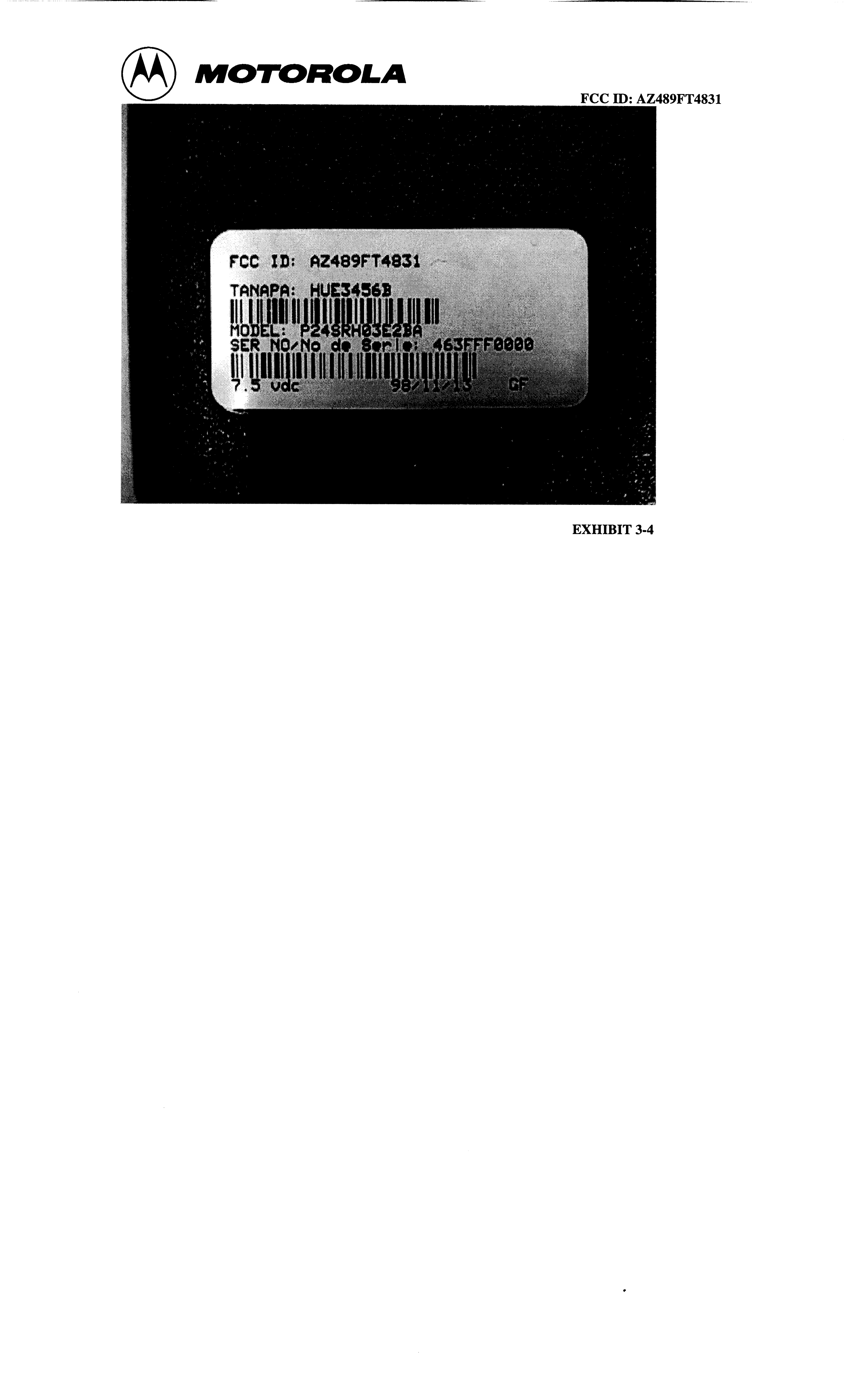
Click to zoom
Application Details
- Equipment Class
- TNF - Licensed Non-Broadcast Transmitter Held to Face
- Date of Grant
- Mar 07, 1999
- Application Purpose
- Original Equipment
- Date of Application
- Dec 21, 1998
- Equipment Note
- Hand Held Portable Radio
- Frequency Range
- 458.00000000 - 470.00000000
- Company
- Motorola Solutions, Inc.
- Country
- United States
Documents & Files
Document Text
Text extracted from the exhibit documents filed with the FCC. Open a document above to read the original.
Users Manual
FCC ID: AZ489FT4831 INSTRUCTION MANUAL X Preliminary Manual attached. Complete Manual attached. FCC ID: AZ489FT4831 EXHIBIT 8 FCC Licensing Information Your Motorola radio operates on FM radio communication frequencies and is subject to the Rules and Regulations of the Federal Communications Commission (FCC). The FCC requires that all operators using Private Land Mobile frequencies obtain a radio license before operating their equipment. Application for your FCC license is made on FCC Form 600 and schedules D, E, and G. To have the forms faxed to you by the FCC, call the FCC Fax-On-Demand system at 1-202-418-0177 from your fax machine and request document 000600 for all forms and instructions. To have the forms mailed to you, call the FCC forms hotline at : 1-800-418-FORM. For questions concerning the license application, contact the FCC at : 1-888-Call-FCC (or 1- 888-225-5322) Before filling out your application, you must first determine your radio frequency. Radio frequency can be determined by first identifying the frequency number the radio is set to and then matching the number to the corresponding frequency in the Frequency Tables. See page ... and ... of this manual for additional information. For questions on determining your radio frequency, please call : 1-800-448-6686 Copyright Information The Motorola products described in this manual may include copyrighted Motorola programs stored in semiconductor memories or other media. Laws in the United States and other countries preserve for Motorola, certain exclusive rights for copyrighted computer programs, including the exclusive right to copy or reproduce in any form, the copyrighted Motorola programs. Accordingly, any copyrighted Motorola computer programs contained in the Motorola products described in this manual may not be copied or reproduced in any manner without the express written permission of Motorola. Furthermore, the purchase of Motorola products shall not be deemed to grant either directly or by implication, estoppel, or otherwise, any license under the copyrights, patents or patent applications of Motorola, except for the normal non-exclusive royalty free license to use that arises by operation of law in the sale of a product. Getting Started Thank you for purchasing a Motorola Spirit radio. Your radio is a product of Motorola’s 50 years of experience as a world leader in the designing and manufacturing of communications equipment. With proper care and use, your Motorola radio should give you years of reliable communication . Contents of Package : • Radio • NiCd Battery Pack • Optional: Charger Tray • Belt Clip• 10 Hour Charger Adapter FCC ID: AZ489FT4831 • Antenna • Operator Manual FCC ID: AZ489FT4831 Batteries CAUTION Do not remove the plastic wrap from the battery pack. This may permanently damage the battery. The Ni-Cd battery ships uncharged, it must be fully charged for 16 hours before use (first charge only). It is recommended that only Motorola batteries and chargers are used with the radio. The Ni-Cd rechargeable battery pack will provide approximately 8 hours of use on a 2 watt radio and 10 hours on a 1 watt radio with normal use i.e. 5% sending messages, 5% receiving messages and 90% in standby mode. To Install/Remove battery : Note : Radio must be in OFF position before installing/removing battery. 1. Push back battery cover latches until you see the orange tabs. 2. Slide battery cover down and lift to remove. 3. To replace/install battery, insert the battery pack with arrows facing you and towards top of radio.. 4. Replace the battery cover and lock latches. 5. To remove battery: remove cover (steps 1 & 2), turn the radio over and tap the battery end of the radio against the palm of your hand. The battery will drop into your hand. Charging the Ni-Cd battery Pack Charging Adapter Instructions : 1. Turn the radio off. 2. Lift accessory cover and plug the Charger Adapter firmly into the small jack (lower hole). 3. Plug the Charger into an electric outlet. The red light on the charger will glow continuously if charging properly. 4. Allow 10 hours for the battery to fully charge. NOTE: For optimum battery life, the battery should not be left charging for prolonged periods after reaching full charge. Charging the battery over the weekend is acceptable. NOTE: Transmitting while radio is charging in the Wall Charger can cause the radio transmitter or the charger to operate improperly. Do not transmit while radio is charging. If radio is on while charging, at least twice as much time is required to charge the battery. Turn the radio off when charging. 10 Hour Desktop Charger Instructions : 1. Connect Desktop Charger and Charger Adapter. 2. Charge the battery while inside the radio by placing the radio in the Charger Tray with radio facing towards you. You can also charge the battery by removing battery from radio and placing it in Charger Tray with silver contacts facing down and arrow facing toward the front. FCC ID: AZ489FT4831 3. The LED light on top of the charger will glow red continuously when radio / battery is inserted in charger. If light does not come on, check radio / battery is properly inserted and check battery/ charger contacts to be sure they are clean. The red LED will continue to glow until the radio / battery is removed from Charger Tray. 4. Allow 10 hours for the battery to fully charge. Note: The Desktop Charger is optional and may not be included in your package. For more information, please contact your place of purchase or call 1-800-448-6686. Low Battery Alert: When the battery is low, the radio will beep 3 to 4 seconds after turning power on, every 10 minutes, and after release of the Push-To-Talk button. Recharge the battery pack immediately to avoid interrupted use. Note: Remove battery pack before storing your radio for extended periods. Batteries corrode over time and may cause permanent damage to your radio. Antenna To attach the antenna, rotate the antenna clockwise onto the top of…
Text truncated - open the document above for the full version.
Attestation Statements
FCC ID: AZ489FT4831 STATEMENT OF CERTIFICATION The technical data supplied with this application, having been taken under my supervision is hereby duly certified. The following is a statement of my qualifications: 1) B.S.E.E. from the University of Miami. 2) M.S.E.E from Florida Atlantic University. 3) 2 years of Design and Development experience in the field of two-way radio communications. Name: Joe Zbib Signature: Date: December 22, 1998 . Position: Electrical Dev. Engineer I hereby certify that the above application was prepared under my direction and that to the best of my knowledge and belief, the facts set forth in the application and accompanying technical data are true and correct: Name: Mark Bradford Signature: Date: December 22, 1998. Position: Senior Resource Manager EXHIBIT 2
Block Diagram
FCC ID: AZ489FT4831 BLOCK DIAGRAMS A general description of the overall circuit is not covered in an instruction manual. This section provides the description of circuits required by subpart 2.983 of the Commissions’ rules. Circuits not described in the manual are covered in this exhibit. The following are included: 1. Means for Frequency Stabilization*4A 2. Means for Modulation Limiting4B and Low Pass Filter* 3. Means for Harmonic Suppression4C 4. Means for Limiting Power*4D * From currently Type Accepted Transmitter FCC ID: AZ489FT3793. EXHIBIT 4 FCC ID: AZ489FT4831 CARRIER FREQUENCY GENERATION AND STABILIZATION BLOCK DIAGRAMS: The carrier frequency is generated using a fractional-N frequency synthesizer inside the ULTZif (U801). This consist of a phase-locked loop circuit with a voltage controlled oscillator (VCO) whose output is fed back to a programmable divider chain. The divide ratios are determined from information stored in the microcomputer and bussed to the synthesizer via a microcomputer. The microcomputer extracts the data for the division ratios as determined by the system select switch or by loading data stored in the memory ICs. Using a time averaged algorithm a combination of divide ratios are used so that the reference frequency can be a much higher value than the value of the frequency resolution. Modulation occurs by a combination of directly coupling the modulation signal to the low pass filter in the loop and by processing the digitized analog modulation signal to alter the divider values. A temperature compensated crystal oscillator at 16.8 MHz and stable to 2.5 parts per million over temperature extremes is used for the frequency reference. The 16.8 MHz reference is further divided into one of three reference frequencies which is compared to the divided down VCO output in a phase detector which in turn provides a DC steering voltage back to the VCO. EXHIBIT 4A FCC ID: AZ489FT4831 MODULATION LIMITING AND LOW PASS FILTER BLOCK DIAGRAMS : The pre-emphasis modulation limiting and low pass filtering of this transmitter are in integrated circuit form on the Audio/Signaling Filter section of the ULTZif (U801). Audio from the microphone initially enters the ULTZif (U801) where it is amplified, filter and pre- emphasized. The limited, filtered audio is then fed through digitally programmable attenuators to the modulation port on the synthesizer module. There is no access to the post limiter in the ULTZif (U801). EXHIBIT 4 B FCC ID: AZ489FT4831 HARMONIC SUPPRESSION CIRCUIT CIRCUIT DESCRIPTION: Attenuation for harmonics is provided by a low pass filter before the RF Power Amplifier and one after it, as well as, the Harmonic Filter after the Antenna Switch. The low pass filter in the RF PA is composed of C503,C504, and L501 on the input and L507 & C522 on the output. The Harmonic Filter is a fifth order Low Pass Chebyshev with 0.1 dB of ripple composed of C101, L101, C103, L102, C102 and C104. For Circuit Diagram refer to the Schematics in exhibit five. EXHIBIT 4C FCC ID: AZ489FT4831 MEANS FOR LIMITING POWER CIRCUIT DESCRIPTION The transmit power Amplifier is a three stage design. The first stage is an MMBR951 transistor with an input level of 3 dBm(2 mW)., and 10-15 dB gain. The second stage utilizes a MRF8372 device(NPN) with a specified maximum output of 0.5 Watts. The third and final stage is a MRF5003 FET with a maximum output of 3.0 Watts. The antenna switch controls the RF signal flow. In transmit mode, the RF signal flow is directed to the Harmonic filter. The output of the harmonic filter is connected to the antenna. For Circuit Diagram refer to the Schematics in Exhibit five. EXHIBIT 4D
Cover Letter(s)
FCC ID: AZ489FT4831 Radio Products Group 8000 West Sunrise Boulevard, Fort Lauderdale, Florida 33322. (954)723-5000 Date: December 22, 1998. Authorization and Evaluation Division Federal Communications Commission Laboratory 7435 Oakland Mills Road Columbia. MD 21046 Att: George Tannahill, Frank Coperich. Subject: Application for Certification of Transmitter with FCC ID: AZ489FT4831. Gentlemen: Motorola Inc, 8000 West Sunrise Boulevard, Fort Lauderdale, Florida, herein submits application for Certification of the subject transmitter. This transmitter is primarily intended for use in a portable radio application with capabilities for clear communications with transmit output power of 1.0 Watt or 30 dBm to 3.0 Watt or 34.75 dBm. The subject transmitter complies with Section 90.203 of the rules in that the operator cannot directly program transmit frequencies using only the unit’s normally accessible external controls. Enclosed is a complete Type Acceptance Application. Contact me (954) 723-5793 or Fax me at (954) 723-4794, if you require any additional information. Sincerely, Mike Ramnath. FCC Liaison.
External Photos
FCC ID: AZ489FT4831 EXTERNAL PHOTOGRAPHS The following photographs are attached. 1.Front view of Radio with Standard Antenna. 2.Front view of Radio with short version Antenna. 3.Front view of Radio with Extended Range Helical Antenna. 4.Back view of Radio (FCC Label location). (2). EXHIBIT 3 FCC ID: AZ489FT4831 1. FRONT VIEW OF UHF WITH STANDARD WHIP ANTENNA EXHIBIT 3-1 FCC ID: AZ489FT4831 2. FRONT VIEW WITH UHF STUBBY HELICAL ANTENNA EXHIBIT 3-2 FCC ID: AZ489FT4831 3. FRONT VIEW OF RADIO WITH EXTENDED RANGE HELICAL. EXHIBIT 3-3 FCC ID: AZ489FT4831 For Exhibit 3-4 see separate External Photo file.
ID Label/Location Info
FCC ID: AZ489FT4831 LIST OF EXHIBITS DESCRIPTION EXHIBIT REFERENCE I. Identification label information12.983-(f) & General Information1a 1. Production Plans2.981-(a) 2. Application References2.1061 3. Data Submittal Procedure 4. Similar Applications II. Certification of Data2 III. External Photographs32.983-(g) IV. Block Diagrams4 1. Frequency Stabilizing4A 2. Modulation Limiting4B and Post Limiter Filter 3.Harmonic Suppression 4C 4.Power Limiting4D V. Schematic Diagrams52.983-(d)-7 VI. Test Report6 1. Data Index6 2. RF Output Data6A2.985 3. Modulation Characteristics2.987 A. Audio Response & Low Pass Filter Response6B, 9C B. Modulation Limiting6D 4. Occupied Bandwidth6E2.989 5. Conducted Spurious Emissions 6F2.991 6. Radiated Spurious Emissions6G2.993 7. Frequency Stability (Temperature & Supply Voltage)6H-1, 9H-22.995 8. Transient Frequency Behavior6I90.214 VII. Test Set-up Procedures72.999 VIII. Instruction Manual8 2.983-(d)-8 IX. Internal Photographs.9 2.983-(g) X. Parts List and Tune-Up procedures102.983-(d)-6, 9 XI. RF Exposure Information112.1093 XII. Operational Description12 2.983- (d)1,2,3,4,5 1. Technical Characteristics 2. Application XIII. Cover Letter13 FCC ID: AZ489FT4831 IDENTIFICATION LABEL LOCATION X See The Attached Photograph Or Sketch Back Of Radio Back Of Radio Under Belt Clip TYPE X The label is a paper polyester film laminate with a pressure sensitive adhesive backing. The adhesive is a permanent type acrylic with a minimum peel strength of 40 oz/ inch. The label is laser etched into the Urethane paint, exposing the Nickel plating on the Zamak casting substrate. Since no adhesive is required, the label is permanent and tamper-proof. (** - NOTE- The label attached below is a paper polyester film laminate, as described above. This is just for sample purposes, as the actual label is laser etched into the casting) MARKINGS (TEXT) See the Attached Photograph, Exhibit 3-4. EXHIBIT 1 FCC ID: AZ489FT4831 GENERAL INFORMATION I.Production Plans—Pursuant 2.983 ( c ). Quantity production is planned. II.Application References -- Pursuant 2.1061 Reference is made to the following Motorola “Application References” 1. Portable Products and their application. 2. Portable Products Transmitter Modulations Methods. III.Data Submittal Procedure: Data is supplied in accordance with Part 2, Sub-part J of the Commissions’ Rules. IV.Similar, currently Type Accepted Transmitter, FCC ID: AZ489FT4824. EXHIBIT 1a
Operational Description
FCC ID: AZ489FT4831 OPERATIONAL DESCRIPTION I.Transmitter Technical Characteristics—Pursuant 2.983 (d) A. RF Power Output1.0 to 3.0 Watt B. Frequency Range 458-470 MHz C. Frequency Stability 0.00025 % D. Emissions 11K0F3E, 16K0F3E (see General Info. ) E. Spurious Emissions 49.02 dBc F. DC Voltage and Current into 7.50 Volts the final RF amplifier stage/stages 850 mAmps -1104 mAmps II.Transmitter Application This transmitter is primarily intended for use in a hand-held two-way portable radio. The radio is characterized by the following features, options and accessories. A.Power Supply Available 1. NiCad Battery X , Mercury Battery , Alkaline Battery , AC , Lead Acid Battery , Nickel Metal Hydride . B.Antenna Available 1. Helical X , Telescopic , Whip , Dipole , Dribble External _________, External __________. C.Squelch Types Available 1. Carrier Squelch X . 2. Tone “Private Line” X . 3. Digital “Private Line” . D.Microphone - Control 1. Handset/Palm Microphone X . 2. 600 Ohm wireline control . E. Maximum Transmit Channel Capability 16 . F.Housing The transmitter will be housed in the housing shown in the accompanying photographs. G.Other Options 1. Single Tone Encoder X 2. Multiple Single Tone Encoder N/A 3. Touch Code Encoder N/A 4. Unit ID Encoder N/A 5. EMS Telemetry Encoder N/A 6. Time out Timer X 7. Voice EncryptionN/A 8. Digital Signaling N/A 9. Sel-Call Decode N/A 10. Trunking N/A EXHIBIT 12
Parts List/Tune Up Info
FCC ID: AZ489FT4831 PARTS LIST AND TUNE-UP PROCEDURE SchematicDesignator Device Circuit Key Non/Motorola Type Application Source U701KXN1229ATCXOReference Motorola U80157W78RF ICULTZIF Motorola U90114S84HC11E09MicroProcessor Motorola U1101LP2951DC RegulatorDC Voltage National U1150LP2951DC RegulatorDC Voltage National Q350MUN511T1Self bias PNPBias voltage switch Motorola Q505 MMBR951NPNFirst stage Amp Motorola Q506MRF8372NPNSecond stage Amp Motorola Q508MRF5003FETFinal stage Amp Motorola Q601NE68530NPNVCONEC Q602NE68530NPNVCONEC Q301NE68530NPNLNA NEC Q302NE68530NPNLNANEC Q303NE68530NPNLNANEC Q501BCW60BNPNBias voltage switch Motorola Q503BCW60BNPNBias voltage switch Motorola Q502MMBT3906PNPBias voltage switch Motorola Q504BSR33PNPBias voltage switch Motorola D6011SV229VARACTORVCO Motorola D6021SV229VARACTORVCO Motorola D401MA4CP101ADIODEAntenna switch Motorola ____________________________________________________________________________ COMMENTS: The Motorola designators are special code numbers for active devices used in Motorola radios. These devices are either identical or derived from the device family listed under Source, by the manufacturer or are proprietary to Motorola. Service people do not have access to any cross-references or given any information on proprietary devices and are prevented from making unauthorized substitutions. EXHIBIT 10 FCC ID: AZ489FT4831 TUNE UP PROCEDURE The following tune-up procedure is for the factory only. There will be no customer tuning. Tuning Procedures There are a total of 5 tuning adjustments. All on-board tuning is performed automatically utilizing software commands. An SCI interface bus is provided for programming. D/A’s replace typical manually adjusted potentiometers. All tuning information is stored in the micro-controller’s internal EEPROM. The order of tuning should be followed as presented in this document. For more detailed information regarding the SCI bus and software protocols, refer to section 3.2. All tuning adjustments should be performed with DC voltage applied to the radio’s power terminals. It is preferable to use a DC Power Supply with voltage sense lines available and to use the sense connections at the radio supply input). Nominal battery voltage for the Model Series is 7.5 +/- 0.1 V. All RF signals from test equipment should be terminated at 50 ohms. “Standard RF input signal level” is defined as 1 mV into 50 ohms, or -47 dBm. “Standard test modulation” is defined as a 1 kHz tone @ +/- 1.5 kHz deviation. Whenever the radio’s codeplug information is changed (i.e., tuning squelch, warping the TCXO, etc.), the checksum byte must also be changed at the same time! If the checksum is not correct, the radio automatically uses a pre-defined set of codeplug values! Table 5.1 UHFVHFVHF FP8 New Channel Business Freqs. FP8 New Channel Business Freqs.FP8 New Channel Business Freqs. *1464.55001154.57001154.5700 *2467.76252154.60002154.6000 *3467.92503151.62503151.6250 *4467.85004151.95504151.9550 5464.5000 Itinerant. 5151.8200 6467.87505151.70006151.8800 7467.90006151.76007151.9400 8467.8125 Itinerant Freqs. 8151.7000 9151.7600 * these frequencies are also the default frequencies for positions/channels1-4 on the radio FCC ID: AZ489FT4831 5.1VCO Gross Adjustment Calculate the frequency error VCO Tune. This application is used to tune the LO VCO tank circuit for each channel to ensure that the assigned frequency will be in the middle of the operating frequency range of the VCO at which the VCO control voltage is in between 1 and 2 volt. • Assume that radio is on and in standby mode. • Send a serial command READ_DATA_REQ to read’s byte 7 of the ULTZIF image. Binary ANDed that byte with hexadecimal byte “F8” to zero out the least significant three bits (bit 59 to bit 60 on the ULTZIF). • Set the radio to receive a given channel. • Measure the VCO control voltage. If the voltage reading is not between specs (1 and 2), change the setting of the byte 7 by O, Ring it with hexadecimal byte “0x” where x is in between 1 to 7. 5.2 Reference Oscillator Adjustment The reference oscillator is a TCXO (Temperature Compensated Xtal Oscillator) with an external warp control. The warp signal is provided by an 8-bit DAC (Digital to Analog Convertor) located on the ULTZIF IC, and is fully programmable via the SCI bus. Ensure that the test equipment (especially the frequency measurement instrument) is on a 10 MHz reference line. Make sure that when this test is run that the codeplug in the test software “sets” the Power amplifier RF_VDAC voltage to its minimum bit setting (ie 00 bit setting). The default codeplug setting for the RF_VDAC (74) will be resumed once this tuning step is complete. A) Key the transmitter, and measure the carrier frequency relative to the radio frequency selected according to the tables in section 5.1. The measurement should be performed at 25 +/- 2 degrees C. Record the frequency error. B) Adjust the warp signal until the frequency error is within the specified limits. Spec limit: +/- 50 Hz 5.3 Modulating Limiting and Balancing Adjustment This application tunes the deviation for the low frequency port and the deviation of the high frequency port to make sure the over all deviation is within the spec limit. Like 5.2, the RF_VDAC tuning value needs to be set to 00 bit setting for this test. Once this tuning step is completed then the default codeplug value for the RF_VDAC (74) is to be reset • Assume the radio is in transmit mode without audio signal presence. Measure the deviation and make sure the reading must be less than 100. • Send a command to make radio operated with PL code of 1 or PL tone of 71.9 Hz. FCC ID: AZ489FT4831 • Set ULTZIF’s PL bit (bit 125) to 1, and ULTZIF’s LODEV bits (bit 116 to 118) to all 0. • Measure the deviation and change the bits 116 to 118 until the deviation is in between 200 and 300 Hz. • Inject the audio signal of 8 mVrms and change bits 119 to 124 until the deviation is between 1350 to 1550 Hz. • Increa…
Text truncated - open the document above for the full version.
RF Exposure Info
FCC ID: AZ489FT4831 RF EXPOSURE INFORMATION: In accordance with 47 CFR 2.1093 (c ), this transmitter has been subjected to routine environmental evaluation for RF exposure and found to be compliant with the limits specified in 47 CFR 2.1093 (d). EXHIBIT 11
Schematics
FCCID: AZ489FT4831 SCHEMATIC DIAGRAMS The following schematic diagrams show circuit connectivity. There will be no service manual. 000 - Schematic Block Diagram 100 - Harmonic Filter 200 - Pre-selector 300 - Automatic Gain Control/LNA 400 - TX PA 500 - VCO 600 - Ref Osc 700 - ULTZIF 800 - Controller EXHIBIT 5 FCCID: AZ489FT4831 EXHIBIT 5-000 FCCID: AZ489FT4831 EXHIBIT 5-100 FCCID: AZ489FT4831 EXHIBIT 5-200 FCCID: AZ489FT4831 EXHIBIT 5-300 FCCID: AZ489FT4831 EXHIBIT 5-400 FCCID: AZ489FT4831 EXHIBIT 5-500 FCCID: AZ489FT4831 EXHIBIT 5-600 FCCID: AZ489FT4831 EXHIBIT 5-700 FCCID: AZ489FT4831
Test Report
FCCID: AZ489FT4831 TEST REPORT MEASUREMENT EXHIBIT NUMBER OF PAGES I RF Power Output6A1 IIAudio Response*6B1 IIILow Pass Filter Response*6C1 IVModulation Limiting* A. 12.5 kHz channel spacing case6D-11 B. 25 kHz channel spacing case6D-21 VOccupied Bandwidth6E 1-45 VIConducted Spurious Emissions6F 1-22 VIIRadiated Spurious Emissions4 A. Tx Vertical - 1 Watt6G-1 B. Tx Vertical - 3 Watt6G-2 D. Tx Horizontal- 1 Watt6G-3 D. Tx Horizontal- 3 Watt6G-4 VIII Frequency Stability A. Temperature*6H-11 B. Supply Voltage *6H-21 IXTransient Frequency Behavior A. Transmitter - ON -1 W-12.5 kHz6I-11 B. Transmitter - OFF -1 W-12.5 kHz6I-21 C. Transmitter - ON -3 W-12.5 kHz6I-31 D. Transmitter - OFF -3 W-12.5 kHz6I-41 E. Transmitter - ON - 25 kHz*6I-51 F. Transmitter - OFF - 25 kHz*6I-61 *Data for 1 and 3 watt are identical so only one plot is provided. EXHIBIT 6 FCCID: AZ489FT4831 RF POWER OUTPUT DATA The RF power output was measured with the indicated voltage applied to and current into the final RF amplifying device. 1 Watt Measured RF output1.05Watt Normal DC Voltage7.50Volts Normal DC Current712mA Primary Supply Voltage7.50Volts 3 Watt Measured RF output2.98Watts Normal DC Voltage7.50Volts Normal DC Current1090mA Primary Supply Voltage7.50Volts EXHIBIT6A FCCID: AZ489FT4831 Audio Frequency Response -20-15-10 -5 05 1015 100 10000 Frequency( Hz ) audiohigh speclo w sp ec EXHIBIT 6B FCCID: AZ489FT4831 Post Limiter Response vs. Frequency -80-70-60-50-40-30-20-10 0 10 1 10 100 Freq(KHz) Respspec From 10K to 30Khz was in the noise floor of instrument. EXHIBIT 6C FCCID: AZ489FT4831 Modulation Limiting vs. Amplitude 0 500 10001500200025003000 -20 -15 -10 -5 0 5 10 15 20 Amplitude(dB) 300 Hz1KHz3KHzspec EXHIBIT 6D-1 FCCID: AZ489FT4831 Modulation Limiting vs. Amplitude 0 500 100015002000250030003500400045005000 -20 -15 -10 -5 0 5 10 15 20 Amplitude (dB ) Deviation (Hz) 300Hz1KHz3KHzSpec EXHIBIT 6D-2 FCCID: AZ489FT4831 OCCUPIED BANDWIDTH DATA 12.5 KHzEXHIBIT 9E-1 Channel Spacing2500 Hz Audio Modulation Emission Type: 11K0F3E Horizontal: 5 kHz /Div. Vertical: 10 dB/Div. Carrier Ref: 0 dB Specification Mask D, 90.210 EXHIBIT 9E-2 2500 Hz & 77 Hz Tone "PL" Modulation Emission Type: 11K0F3E Horizontal: 5 kHz /Div. Vertical: 10 dB/Div. Carrier Ref: 0 dB Specification Mask D, 90.210 25 KhzEXHIBIT 9E-3 Channel Spacing2500 Hz Audio Modulation Emission Type: 16K0F3E Horizontal: 5 kHz /Div. Vertical: 10 dB/Div. Carrier Ref: 0 dB Specification Mask B, 90.210 EXHIBIT 9E-4 2500 Hz & 77 Hz Tone "PL" Modulation Emission Type: 16K0F3E Horizontal: 5 kHz /Div. Vertical: 10 dB/Div. Carrier Ref: 0 dB Specification Mask B, 90.210 CARSON'S RULE 11K0F3E: BW = 2(M + D) BW = 2 (3 kHz maximum modulation frequency + 2.5 kHz deviation) BW = 2 (5.5) BW = 11 kHz 16K0F3E: BW=2(3+5)=16kHz EXHIBIT 6E FCC ID : AZ489FT4831 EXHIBIT 6E-1 FCC ID : AZ489FT4831 EXHIBIT 6E-2 FCC ID : AZ489FT4831 EXHIBIT 6E-3 FCC ID : AZ489FT4831 EXHIBIT 6E-4 FCC ID : AZ489FT4831 EXHIBIT 6F-1 FCC ID : AZ489FT4831 EXHIBIT 6F-2 FCC ID : AZ489FT4831 FC C _UHF_1WATT_Tra nsm it_458.025M Hz_Ve rtic a l Pola riza tion FCC ID: AZ489FT4831 -40-35-30-25-20-15-10 916.05 1374.03 1832.10 2290.13 2748.15 3206.18 3664.20 4122.23 4580.25 Fre que nc y (MHz) Emission Level(dBm) To t a l d BmFCC Maximum Emission Limit (dBm) EXHIBIT 6G-1 FCC ID : AZ489FT4831 FC C _UHF_1WATT_Tra nsm it_458.025M Hz_Horizonta l Pola riza tion FCC ID: AZ489FT4831 -45-40-35-30-25-20-15-10 916.05 1374.03 1832.10 2290.13 2748.15 3206.18 3664.20 4122.23 4580.25 Fre que nc y (MHz) Emission Level(dBm) M e a sure d Em ission Eq uiva le nt Powe r into id e a lDipole (dBm)FCC Maximum Emission Limit (dBm) EXHIBIT 6G-2 FCC ID : AZ489FT4831 EXHIBIT 6G-3 Tx Radiated Spurious Emissions(UHF_3Watt_Vertical) -100.00 -90.00-80.00-70.00-60.00-50.00-40.00-30.00-20.00-10.00 0.00 2*Fc 3*Fc 4*Fc 5*Fc 6*Fc 7*Fc 8*Fc 9*Fc 10*Fc Harmonics of Fc Amplitude (dBm dBmFCC limit FCC ID : AZ489FT4831 Tx Radiated Spurious Emissions(UHF_3Watt_Horizontal) -120.00-100.00 -80.00-60.00-40.00-20.00 0.00 2*Fc 3*Fc 4*Fc 5*Fc 6*Fc 7*Fc 8*Fc 9*Fc 10*Fc Harmonics of Fc Amplitude (dBm dB mFCC limit FCC ID : AZ489FT4831 Frequency Stability over Temperature -3.0-2.0-1.0 0.01.02.03.0 -30 -20 -10 0 10 20 30 40 50 60 Temperature(degrees C) Freq Error(ppm)upper speclower spec EXHIBIT 6H-1 FCC ID : AZ489FT4831 Frequency Error over Voltage (ppm) -3.00-2.00-1.00 0.001.002.003.00 6.00 6.50 7.00 7.50 8.00 8.50 9.00 Supply Voltage(V) Freq Error(ppm)upper speclower spe c EXHIBIT 6H-2 FCC ID : AZ489FT4831 EXHIBIT 6I-1 FCC ID : AZ489FT4831 EXHIBIT6I 2 FCC ID: AZ489FT4831 For Exhibits 6I 3, 4,5 6---See attachment.
Test Setup Photos
FCCID: AZ489FT4831 TEST REPORT MEASUREMENT EXHIBIT NUMBER OF PAGES I RF Power Output6A1 IIAudio Response*6B1 IIILow Pass Filter Response*6C1 IVModulation Limiting* A. 12.5 kHz channel spacing case6D-11 B. 25 kHz channel spacing case6D-21 VOccupied Bandwidth6E 1-45 VIConducted Spurious Emissions6F 1-22 VIIRadiated Spurious Emissions4 A. Tx Vertical - 1 Watt6G-1 B. Tx Vertical - 3 Watt6G-2 D. Tx Horizontal- 1 Watt6G-3 D. Tx Horizontal- 3 Watt6G-4 VIII Frequency Stability A. Temperature*6H-11 B. Supply Voltage *6H-21 IXTransient Frequency Behavior A. Transmitter - ON -1 W-12.5 kHz6I-11 B. Transmitter - OFF -1 W-12.5 kHz6I-21 C. Transmitter - ON -3 W-12.5 kHz6I-31 D. Transmitter - OFF -3 W-12.5 kHz6I-41 E. Transmitter - ON - 25 kHz*6I-51 F. Transmitter - OFF - 25 kHz*6I-61 *Data for 1 and 3 watt are identical so only one plot is provided. EXHIBIT 6 FCCID: AZ489FT4831 RF POWER OUTPUT DATA The RF power output was measured with the indicated voltage applied to and current into the final RF amplifying device. 1 Watt Measured RF output1.05Watt Normal DC Voltage7.50Volts Normal DC Current712mA Primary Supply Voltage7.50Volts 3 Watt Measured RF output2.98Watts Normal DC Voltage7.50Volts Normal DC Current1090mA Primary Supply Voltage7.50Volts EXHIBIT6A FCCID: AZ489FT4831 Audio Frequency Response -20-15-10 -5 05 1015 100 10000 Frequency( Hz ) audiohigh speclo w sp ec EXHIBIT 6B FCCID: AZ489FT4831 Post Limiter Response vs. Frequency -80-70-60-50-40-30-20-10 0 10 1 10 100 Freq(KHz) Respspec From 10K to 30Khz was in the noise floor of instrument. EXHIBIT 6C FCCID: AZ489FT4831 Modulation Limiting vs. Amplitude 0 500 10001500200025003000 -20 -15 -10 -5 0 5 10 15 20 Amplitude(dB) 300 Hz1KHz3KHzspec EXHIBIT 6D-1 FCCID: AZ489FT4831 Modulation Limiting vs. Amplitude 0 500 100015002000250030003500400045005000 -20 -15 -10 -5 0 5 10 15 20 Amplitude (dB ) Deviation (Hz) 300Hz1KHz3KHzSpec EXHIBIT 6D-2 FCCID: AZ489FT4831 OCCUPIED BANDWIDTH DATA 12.5 KHzEXHIBIT 9E-1 Channel Spacing2500 Hz Audio Modulation Emission Type: 11K0F3E Horizontal: 5 kHz /Div. Vertical: 10 dB/Div. Carrier Ref: 0 dB Specification Mask D, 90.210 EXHIBIT 9E-2 2500 Hz & 77 Hz Tone "PL" Modulation Emission Type: 11K0F3E Horizontal: 5 kHz /Div. Vertical: 10 dB/Div. Carrier Ref: 0 dB Specification Mask D, 90.210 25 KhzEXHIBIT 9E-3 Channel Spacing2500 Hz Audio Modulation Emission Type: 16K0F3E Horizontal: 5 kHz /Div. Vertical: 10 dB/Div. Carrier Ref: 0 dB Specification Mask B, 90.210 EXHIBI…
Text truncated - open the document above for the full version.
Contact Information
Applicant
Deanna Zakharia(Regulatory Compliance Manager)
Technical Contact
Motorola IncMike Ramnath
[email protected]954-723-5793
8000 West Sunrise Blvd · Fort Lauderdale, Florida · United States
Technical Specifications
| # | Rule Parts | Frequency Range | Power Output | Emission | Tolerance |
|---|---|---|---|---|---|
| 4 | 90.210,95A | 458 MHz - 470 MHz | 1 W | 11K0F3E | 2.5 ppm |
Other Applications from Motorola Solutions, Inc.

AZ489FT4980
Sep 08, 2026Portable two way radio
Equipment Class
TNF - Licensed Non-Broadcast Transmitter Held to FaceAZ489FT4981
Aug 14, 2026Handheld Portable - TANAPA BPR 45 400-470 MHZ 4W NKP
Equipment Class
TNF - Licensed Non-Broadcast Transmitter Held to Face
AZ489FT7187
Jul 13, 2026Portable 2-Way Radio with Bluetooth, Bluetooth LE, WIFI 2.4GHz, WIFI 5GHz, LTE
Equipment Class
DSS - Part 15 Spread Spectrum TransmitterAZ499FT6031
May 11, 2026Operation Critical Wireless Earpiece PTT
Equipment Class
DSS - Part 15 Spread Spectrum Transmitter
AZ499FT5879
Dec 19, 20252-way Portable Radio with BT, BTLE, WIFI, NFC and LTE
Equipment Class
DSS - Part 15 Spread Spectrum Transmitter