AZ489FT4838Hand Held Transmitter
Motorola Solutions, Inc.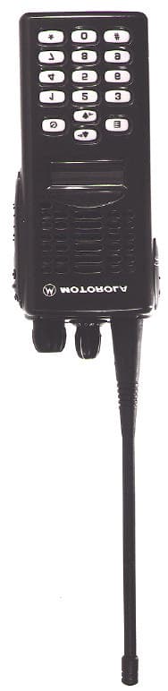
Click to zoom
Application Details
- Equipment Class
- TNF - Licensed Non-Broadcast Transmitter Held to Face
- Date of Grant
- Feb 14, 2000
- Application Purpose
- Original Equipment
- Date of Application
- Oct 21, 1999
- Equipment Note
- Hand Held Transmitter
- Frequency Range
- 450.00000000 - 512.00000000
- Company
- Motorola Solutions, Inc.
- Country
- United States
Documents & Files
Document Text
Text extracted from the exhibit documents filed with the FCC. Open a document above to read the original.
Users Manual
Copyright Information The Motorola products described in this manual may include copyrighted Motorola computer programs stored in semiconductor memories or other mediums. Laws in the United States and other countries preserve for Motorola certain exclusive rights for copyrighted computer programs, including the exclusive right to copy or reproduce in any form the copyrighted computer program. Accordingly, any copyrighted Motorola computer programs contained in the Motorola products described in this instruction manual may not be copied or reproduced in any manner without the express written permission of Motorola. Furthermore, the purchase of Motorola products shall not be deemed to grant either directly or by implication, estoppel, or otherwise, any license under the copyrights, patents, or patent applications of Motorola, except for the normal non-exclusive, royalty free license to use that arises by operation of law in the sale of a product.© 1999 by Motorola, Inc.All Rights Reserved.Motorola Technology Sdn. Bhd. (Company No. 455657-H),Bayan Lepas Free Industrial Zone, Phase 3,11900 Penang, Malaysia.Printed in Malaysia. , Motorola, trademark of Motorola, Inc. #ELP_Display.book Page 1 Friday, May 14, 1999 5:39 PM English LIMITED WARRANTY & LIABILITY MOTOROLA COMMUNICATION PRODUCTS I. WHAT THIS WARRANTY COVERS AND FOR HOW LONG: MOTOROLA ELECTRONICS PTE LTD ("MOTOROLA") warrants the MOTOROLA manufactured TWO-WAY RADIO Products listed below ("Product") against defects in material and workmanship under normal use and service for a period of time from the date of purchase as scheduled below:TWO-WAY RADIO Mobile and Portable Units Two (2) Years Product Accessories (including battery, antenna,charger, belt clip etc.) One (1) Year Motorola, at its option, will at no charge either repair the Product (with new or reconditioned parts), replace it (with a new or reconditioned Product), or refund the purchase price of the Product during the warranty period provided it is returned in accordance with the terms of this warranty. Replaced parts or boards are warranted for the balance of the original applicable warranty period. All replaced parts of Product shall become the property of MOTOROLA.This express limited warranty is extended by MOTOROLA to the original end user purchaser only and is not assignable or transferable to any other party. This is the complete warranty for the Product manufactured by MOTOROLA. MOTOROLA assumes no obligations or liability for additions or modifications to this warranty unless made in writing and signed by an officer of MOTOROLA. Unless made in a separate agreement between MOTOROLA and the original end user purchaser, MOTOROLA does not warrant the installation, maintenance or service of the Product.MOTOROLA cannot be responsible in any way for any ancillary equipment not furnished by MOTOROLA which is attached to or used in connection with the Product, or for operation of the Product with any ancillary equipment, and all such equipment is expressly excluded from this warranty. Because each system which may use the Product is unique, MOTOROLA disclaims liability for range, coverage, or operation of the system as a whole under this warranty. II. GENERAL PROVISIONS: This warranty sets forth the full extent of MOTOROLA'S responsibilities regarding the Product. Repair, replacement or refund of the purchase price, at MOTOROLA'S option, is the exclusive remedy. THIS WARRANTY IS GIVEN IN LIEU OF ALL OTHER EXPRESS WARRANTIES. IMPLIED WARRANTIES, INCLUDING WITHOUT LIMITATION, IMPLIED WARRANTIES OF MERCHANTABILITY AND FITNESS FOR A PARTICULAR PURPOSE, ARE LIMITED TO THE DURATION OF THIS LIMITED WARRANTY. IN NO EVENT SHALL MOTOROLA BE LIABLE FOR DAMAGES IN EXCESS OF THE PURCHASE PRICE OF THE PRODUCT, FOR ANY LOSS OF USE, LOSS OF TIME, INCONVENIENCE, COMMERCIAL LOSS, LOST PROFITS OR SAVINGS OR OTHER INCIDENTAL, SPECIAL OR CONSEQUENTIAL DAMAGES ARISING OUT OF THE USE OR INABILITY TO USE SUCH PRODUCT, TO THE FULL EXTENT SUCH MAY BE DISCLAIMED BY LAW. III. HOW TO GET WARRANTY SERVICE: You must provide proof of purchase (bearing the date of purchase and Product item serial number) in order to receive warranty service and, also, deliver or send the Product item, transportation and insurance prepaid, to an authorized warranty service location. Warranty service will be provided by Motorola through one of its authorized warranty service locations. If you first contact the company which sold you the Product (e.g., dealer or communication service provider), it can facilitate your obtaining warranty service. You can also call Motorola Service centres at65-4865560 (Singapore), 8610-68437222 ext. 3356(China),822-3440-7400(Korea), 9180-6657676/7/8/9(India),613-9425-3533(Australia), 852-2590-4800(Hong Kong), or Asia Pacific Help Desk 65-485-5333(Singapore),8610-68438231(China). #ELP_Display.book Page 1 Friday, May 14, 1999 5:39 PM English IV. WHAT THIS WARRANTY DOES NOT COVER: A) Defects or damage resulting from use of the Product in other than its normal and customary manner. B) Defects or damage from misuse, accident, water, or neglect. C) Defects or damage from improper testing, operation, maintenance, installation, alteration, modification, or adjustment. D) Breakage or damage to antennas unless caused directly by defects in material workmanship. E) A Product subjected to unauthorized Product modifica- tions, disassemblies or repairs (including, without limita-tion, the addition to the Product of non-Motorola supplied equipment) which adversely affect perfor-mance of the Product or interfere with Motorola's normal warranty inspection and testing of the Product to verify any warranty claim. F) Product which has had the serial number removed or made illegible. G) Rechargeable batteries if: 1) any of the seals on the battery enclosure of cells are broken or show evidence of tampering. 2) the damage or defect is caused by charging or using the battery in equipment or service other than the Produ…
Text truncated - open the document above for the full version.
Attestation Statements
MOTOROLA INC FCC ID: AZ489FT4838 EXHIBIT 3 STATEMENT OF CERTIFICATION The technical data supplied with this application, having been taken under my supervision is hereby duly certified. The following is a statement of my qualifications: I have received an Electrical & Electronics Engineering degree from the University of Canterbury, New Zealand in 1991. I have more than 5 years of Product Development experience in the field of two-way radio communication. NAME: YIP, Khai Biau SIGNATURE: YIP,Khai Biau DATE: 9 th . September. 1999 POSITION: Engineering Group Leader I hereby certify that the above application was prepared under my direction and that to the best of my knowledge and belief, the facts set forth in the application and accompanying technical data are true and correct: NAME: Ng Yong Kian SIGNATURE: YK Ng DATE: 9 th . September.1999 POSITION: Engineering Manager
Block Diagram
MOTOROLA INC.FCC ID: AZ489FT4838 EXHIBIT 5 CIRCUIT DESCRIPTION A general description of the overall circuit is covered in the instruction manual. This section provides the description of circuits required by subpart 2.983 of the Commissions’ rules. The following are included: 1) Means for Frequency Stabilization 2) Means for Modulation Limiting 3) Means for Attenuation of Higher Audio Frequencies 4) Means for Attenuation of Spurious Emissions 5) Means for Limiting Output Power 6) Means for Modulation Techniques 7) Means for Transient Frequency Behavior MOTOROLA INC.FCC ID: AZ489FT4838 EXHIBIT 5 1) Means For Frequency Stabilization Frequency stability is maintained by a reference oscillator/programmable temperature compensation circuit located in the frequency synthesizer IC U201. The oscillator is a Colpitts design with an amplifier in the IC. The 16.8 MHz crystal FL201, varactor and feedback capacitors are external circuitry. A control voltage applied to the varactor via the programmable compensation circuit maintains the frequency stability to within +/-2.5 ppm over temperature. Frequency tuning, also from the programmable compensation circuit, has 128 steps of resolution. Each 16.8 MHz crystal is numerically coded providing its unique characteristic over the temperature range. With the crystal temperature characteristic known, a computed compensation characteristic is programmed into the compensation algorithm. 2) Means for Limiting Modulation Modulation limiting is accomplished within the custom IC, U404. The limiting action itself occurs at the rails (i.e., 3.3V and ground). Using an opamp with feedback, very hard limiting is obtained. The limited modulation signal is then input through a low-pass splatter filter then to an electronic attenuator within U404 in order to adjust for variations in modulation sensitivities of the frequency synthesizer. The electronic attenuator is controlled by the radio’s micro-processor, U409. To keep the deviation constant over the RF frequency range & channel bandwidth, the microcomputer adds the proper correction factor to the attenuator. 3) Means for Attenuation Of Higher Audio Frequencies The output of the limiter is applied to a low-pass splatter filter. This filter is a fifth-order switched capacitor filter with the rolloff corner located at 3000 Hz. The output of the low-pass filter is input to the electronic attenuator before routing to the modulator. 4) Means For Attenuation Of Spurious Emissions The final stage of the RF power amplifier circuit feeds a low-pass filter in order to attenuate harmonics of the carrier frequency as well as any spurious signals. The filter is a Elliptic 7 element design using LC lump elements. 5) Means For Limiting Output Power The radio utilizes a current sense ALC IC U102 to regulate its output power. The current sensing resistor R102 provides a feedback signal to U102. This signal is then compared to the preprogrammed current reference and the error signal is amplified and used to generate a control voltage to control the bias for Driver U101 and final stage RF Power Amplifier, Q110. 6) Means Modulation Techniques The transmitter is capable of the following types of modulation: i) Modulation of PL (Private Line) - Direct FM tone modulation of 67 Hz to 250.3 Hz at 15% of full system deviation. ii) Modulation of DPL (Digital Private Line) - Direct FM modulation at 134 BPS at 15% of full system deviation. iii) Modulation of DTMF tones at nominally 60% of full system deviation Direct FM of PL or DPL is generated by a 6-bit D/A converter contained within U404. The frequency-determining clock signal is generated by the radio microcomputer. The modulation signal is processed through a five pole switched capacitor filter. The output of the filter is input to the electronic attenuator circuit. The microcomputer adjusts the attenuator to compensate for modulation sensitivity variations of the synthesizer & channel bandwidth ensuring 15% of full system deviation for PL and DPL. DTMF tones are generated by the audio processing IC, U404. The tones are routed and processed in the same manner as the voice signals. MOTOROLA INC.FCC ID: AZ489FT4838 EXHIBIT 5 7) Means of Transient Frequency Behavior RF power amplifier input impedance swings very wild during sudden turn on. The drastic impedance change can pull or shift the VCO frequency momentarily. This will cause interference to the adjacent channel user. It is very hard to eliminate the problem totally. But FCC has come up a certain requirement on how much power and frequency deviation is allowed to happen during a specific time. This radio is design in such away that the VCO and RF power amplifier are properly isolated. This is achieved by putting a three dB pad in the VCO buffer and the RF PA Pre-driver. Controlling the rate of power rise and down helps significantly in reducing the transients.
Cover Letter(s)
MOTOROLA INC.FCC ID: AZ489FT4838 LIST OF EXHIBITS DESCRIPTIONEXHIBITFCC REFERENCE l.Cover Letter12.1033 llIdentification label information22.983-(f) & General Information2A2.981-(c) & 2.1061 1. Production Plans 2. Application References 3. Data Submittal Procedures IIICertification Of Data32.907 IVExternal Photographs42.983-(g) VBlock Diagrams or Circuit Descriptions52.983-(d)-10,11 1. Frequency Stabilization 2. Modulation Limiting 3. Attenuation Of Higher Audio Frequencies 4. Attenuation Of Spurious Emissions 5. Limiting Output Power 6. Modulation Techniques 7. Transient Frequency Behavior VISchematic Diagrams62.983-(d)-7 VIITest Report7 1. Data Index7 2. RF Output Data7A2.985 (a) 3. Modulation Characteristics2.987 (a) a) Audio Response7B b) Low Pass Filter Response7C c) Modulation Limiting7D 4. Occupied Bandwidth7E2.989 5. Conducted Spurious Emissions7F2.991 6. Radiated Spurious Emissions7G2.993 7. Frequency Stability (Temp. & Supply Volt) 7H & 7I2.995 8. Transient Frequency Behavior7J2.2.19(EIA/TIA SP-2218) VIIITest Set-Up Procedures8 a) Test Equipment Used b) Method Of Measurements c) Emission Designator Information 1XInstruction Manual9 XInternal Photograph(s)102.983-(g) XIParts List & Tune-Up Procedures11 & 11A2.983-(d)-6 & 2.983-(d)-9 XIIRF Exposure Information12 XIIIOperational Description13 a) Technical Characteristics2.983-(d)-1,2,3,4,5 b) Application MOTOROLA INC.FCC ID: AZ489FT4838 EXHIBIT 1 Date:October 22, 1999. Authorization & Evaluation Division Federal Communications Commission Laboratory 7435 Oakland Mills Road Columbia, MD 21046 Subject: Application for Certification of Transmitter with FCC ID: AZ489FT4838. Attention: Frank Coperich. Gentlemen: Motorola Inc, 8000 West Sunrise Boulevard, Fort Lauderdale, Florida, herein submits it’s application for Certification of the subject transmitter. This transmitter is primarily intended for use in a portable radio application with capabilities for communications with a transmit power of 1 -- 4 Watt. The Power is variable 25% of the value listed (1— 4 Watt). The subject transmitter complies with Section 90.203 of the rules in that the operator cannot directly program transmit frequencies using only the unit's normally accessible external controls. Enclosed is a complete Certification application. Contact me at (954) 723-5793 if you require any additional information. Sincerely, Mike Ramnath FCC Liaison Email: [email protected] Fax (954) 723-4794
External Photos
MOTOROLA INC.FCC ID: AZ489FT4838 EXHIBIT 4 EXTERNAL PHOTOGRAPHS Index to Photographs This exhibit contains the photographs of this equipment as follows: 1EXHIBIT 4-AFront View (**Plain Model) 2EXHIBIT 4-BFront View (**Display Model) 3EXHIBIT 4-CBack View (**Plain & Display Model) 4EXHIBIT 4-DTop View (**Plain & Display Model) 5 EXHIBIT 4-ESide View (**Plain & Display Model) 6EXHIBIT 4-FSide View (**Plain & Display Model) 7EXHIBIT 4-GModel Description NOTE: ** Refer to Exhibit 4-G for model description. MOTOROLA INC.FCC ID: AZ489FT4838 EXHIBIT 4A Front View (**Plain Model) MOTOROLA INC.FCC ID: AZ489FT4838 EXHIBIT 4B Front View (**Display Model) MOTOROLA INC.FCC ID: AZ489FT4838 EXHIBIT 4C Back View (**Plain & Display Model) MOTOROLA INC.FCC ID: AZ489FT4838 EXHIBIT 4D Top View (**Plain & Display Model) MOTOROLA INC.FCC ID: AZ489FT4838 EXHIBIT 4E Side View (PTT Lever For **Plain & Display Model) MOTOROLA INC.FCC ID: AZ489FT4838 EXHIBIT 4F Side View (External Mic, Speaker & SCI Jacks for **Plain & Display Model) MOTOROLA INC.FCC ID: AZ489FT4838 EXHIBIT 4-G MODEL DESCRIPTION Plain Model NumberNameplate AZH34SDC9AA2--GP308 MDH34SDC9AA1--P040 LAH34SDC9AA1--PRO3150 AAH34SDC9AA1--CT250 AAH34SDC9AA2--CT250 Display Model NumberNameplate AZH34SDH9AA6--- MDH34SDH9AA6--P080 LAH34SDH9AA6--PRO3150 AAH34SDH9AA6--CT450 AAH34SDH9DU6--CT450.LS AAH34SDF9DU6--CT450.LS
ID Label/Location Info
MOTOROLA INC. FCC ID: AZ489FT4838 EXHIBIT 10 INTERNAL PHOTOGRAPHS Index To Photographs This exhibit contains, on the following ten pages, photographs of this equipment as follows: 1EXHIBIT 10-AView o Battery Contact & FCC Label Location (**Plain & Display Model) 2EXHIBIT 10-BView with The Front Housing Open Up (**Plain Model) 3EXHIBIT 10-CView with The Front Housing Open Up (**Display Model) 4EXHIBIT 10-DView with The Back Casting Open Up (**Plain & Display Model) 5EXHIBIT 10-ETop (Front Housing) Side Of RF/Controller Board With Shields Removed (**Plain & Display Model) 6EXHIBIT 10-FBottom (Casting) Side Of RF/Controller Board With Shields Removed (**Plain & Display Model) 7EXHIBIT 10-GTypes Of Antennas (**Plain & Display Model) 8EXHIBIT 10-HTypes Of Batteries - Ni-MH (**Plain & Display Model) 9EXHIBIT 10-ITypes Of Batteries - Ni-Cd (**Plain & Display Model) 10EXHIBIT 10-JView Of Batteries Charging Contact (**Plain & Display Model) NOTE: ** - Refer to Exhibit 4-G for Model Description MOTOROLA INC. FCC ID: AZ489FT4838 EXHIBIT 10A View Of Battery Contact & FCC Label Location (**Plain & Display Model) Exploded View Of FCC Label Battery Contact FCC Label Location MOTOROLA INC. FCC ID: AZ489FT4838 EXHIBIT 10B View With Front Housing Open up (**Plain Model) MOTOROLA INC. FCC ID: AZ489FT4838 EXHIBIT 10C View With Front Housing Open up (**Display Model) MOTOROLA INC. FCC ID: AZ489FT4838 EXHIBIT 10D View With Back Casting Open up (**Plain & Display Model)
Internal Photos
MOTOROLA INC. FCC ID: AZ489FT4838 EXHIBIT 10E Top (Front Housing) Side of RF/Controller Board with Shields Removed. (**Plain & Display Model) MOTOROLA INC. FCC ID: AZ489FT4838 EXHIBIT 10F Bottom (Casting) Side Of RF/Controller Board With Sheilds Removed. (**Plain & Display Model) MOTOROLA INC. FCC ID: AZ489FT4838 EXHIBIT 10G Types Of Antenna (**Plain & Display Model)
Internal Photos
MOTOROLA INC.FCC ID: AZ489FT4838 EXHIBIT 10H Types Of Batteries - Ni-MH (**Plain & Display Model) MOTOROLA INC.FCC ID: AZ489FT4838 EXHIBIT 10I Types Of Batteries Ni-Cd (**Plain & Display Model) MOTOROLA INC.FCC ID: AZ489FT4838 EXHIBIT 10I View Of Batteries Charging Contact (**Plain & Display Model)
Operational Description
MOTOROLA INC FCC ID: AZ489FT4838 EXHIBIT 14-1 OPERATIONAL DESCRIPTION A.Transmitter Technical Characteristics -- Pursuant 2.983 (d) a. RF Power Out:1W to 4W (Variable Power) b. Transmit Frequency Range:450 – 512 MHz c. Receive Frequency Range:450 – 512 MHz d. Frequency Stability:2.5 PPM e. Emissions16K0F3E & 11K0F3E (See Exhibit 8-5) f. Spurious Emissions25uW g. DC Voltage and Current into7.5 VDC the final RF amplifier stage/stages1.5 A B.Transmitter Application This transmitter is primarily intended for use in a portable environment. It is characterized by the following features, options, and accessories. a. Power Supply Available: i. NiCd AFAT Battery ii. NiCd Battery iii. NiMH AA Battery iv. NiMH AA FM Battery b. Antenna Available: i. Helical Antenna ii. Whip antenna c. Squelch Type Available: i. Carrier Squelch ii. Tone “Private Line” iii. Digital “Private Line” iv. DTMF v. Quick Call II d. Microphone - Control: i. Handset/Palm Microphone e. Maximum Transmit Channel Capability: i. 16 Channel f. Housing: i. The transmitter will be housed in the housing shown in the accompanying photographs g. Other Options: i. Time out Timer h. The minimum voltage for the micro-P to operate is 3.3V.
Parts List/Tune Up Info
MOTOROLA INC. FCC ID: AZ489FT4838 EXHIBIT 11 FUNCTION OF RF SEMICONDUCTORS AND OTHER ACTIVE DEVICES SCHEMATICPARTCIRCUITOPERATINGINDUSTRY KEYNUMBERAPPLICATIONFREQUENCYEQUIVALENT CR10148-80973Z02ANTENNA SWITCH450-512 MHzMA4PH261 CR10248-02245J41ANTENNA SWITCH450-512 MHzHSMP3820 CR10551-85963A15POWER AMPLIFIER 450-512 MHz LM50 CR201 48-02233J09SYNTHESIZER16.8 MHz IMN10 CR203 48-62824C03TX VCO FREQ430-470 MHz1SV232 CR24148-05649Q13RX. VCO355-425 MHz1SV228 CR242 & CR24348-62824C01RX. VCO355-425 MHz1SV229 CR25148-62824C01TX. VCO450-512 MHz1SV229 CR301 & CR30248-62824C01RX. SYSTEM450-512 MHz1SV229 CR30348-80154K03ESD PROTECTIONDCMMBD353 CR304 & CR30548-62824C01RX. SYSTEM450-512 MHz1SV229 CR30648-02245J42MIXERDCHSMP3820 CR31048-62824C012ND OSCILLATOR90.2 MHz1SV229 CR414, CR412 & CR41348-02245J47REVERSE CURRENT DCRB471E PROTECTION CR44048-13833C02REVERSE CURRENTDCMMBD6100 PROTECTION CR50148-80107R01REVERSE CURRENTDCBYD17D PROTECTION CR50348-05729G49LEDDCBRPY1204W Q11048-02245J55POWER AMPLIFIER450-512 MHzPRF1507 Q111, Q210, Q260, Q261 &48-02245J50DC SWITCHDCUMC5N Q417, Q418, Q506 Q24148-05218N63VCO OSCILLATOR450-512 MHzBFQ67W Q30148-02245J44RF AMPLIFIER450-512 MHzHP415 Q30248-02245J44IF AMPLIFIER45.1 MHzHP415 Q315, Q421 & Q50548-80214G02DC SWITCHDCMMBT3904 Q32048-05218N632ND OSCILLATOR90.2 MHzBFQ67W Q40048-09579E18DC SWITCHDCTP0101T Q403, Q43348-80214G02DC SWITCHDCMMBT3904 Q405 & Q41048-02245J54DC SWITCHDCUMG5 Q42048-05128M67AMPLIFIERDCMMBT3906 Q418 Q419, Q431 & Q50251-80159R01DC SWITCHDCLM50 U10151-055109Z67TRANSMITTER SYSTEM450-512 MHzCUSTOM U10251-85765B01TRANSMITTER SYSTEM450-512 MHzCUSTOM U20151-85963A27FGU16.8 MHzCUSTOM U21151-02463J61FGUDCTC7SET04FU U24151-05750U54FGU450-512 MHzCUSTOM U24751-05739X055V VOLTAGE REGULATORDCADP3300 U24851-02463J583.3V VOLTAGE REGULATORDCLP2980 U30151-09632D83RX. SYSTEMCUSTOM U40051-02463J403.3V VOLTAGE REGULATORDCAT49BV020 U40451-85963A53AUDIO SYSTEMAUDIOCUSTOM U40651-02463J59CONTROLLER SYSTEM1.83 MHzAT49HLV010 U40951-02463J56CONTROLLER SYSTEM1.83 MHzMC74HC4066 U41051-02463J573.3V VOLTAGE REGULATORDCTDA8547 U42051-02463J44AUDIO AMPLIFIERAUDIOTC7SET04FU VR440-VR444, VR431 &48-02245J51ESD PROTECTION DIODEDCBZX284_6V8 VR506 VR450 & VR45148-02245J53ESD PROTECTION DIODEDCBZX284_C10 VR439, VR432, VR43348-80140L15ESD PROTECTION DIODEDCMMBZ5240B VR50148-13830A18ESD PROTECTION DIODEDCMMBZ5235B U60251-02463J49KEYPAD BOARDLMC7211 MOTOROLA INC. FCC ID: AZ489FT4838 EXHIBIT 11A-1 TUNING PROCEDURES 1. Tuning frequencies These frequencies should be used for transmitter tuning. To avoid interference, the factory should use a frequency offset of 100KHz from these frequencies for an receiver tuning or testing. Test/Tune FreqUHF Band 2 F1450.025 F2462.850 F3475.675 F4488.500 F5501.325 F6514.150 F7526.975 Table 1.1 This procedure was written in the sequence that the radio is to be tuned. The following points should be noted: 1) Radio controller refers to the microprocessor in the radio. 2) Tester/test controller refers to external test system (hardware as well as software). 3) Values in tables may change to improve yield. 4) Disable LLE for all tuning and testing. 2. PRO -SCANNING PROGRAMMING 2.1 Flashing 2.2 Download default codeplug 2.3 Scan the 2D barcode of the Reference xtal 2.3.1 Decode of the barcode a)Decode the crystal code to get crystal maximum ppm, crystal inflection temperature (xtal_infl_temp) and crystal curve ppm(t)(crystal ppm at given temperature) and store them in xtal_max_ppm, xtal_infl_temp and xtal_curve_ppm(t). The following equations are used to calculate the above parameters q1=(dig1*10)+dig2 q2=(dig3*100)+(dig4*10)+dig5 q3=(dig6*10)+dig7 xtal_infl_temp=q1/10+22 a1=-q2/1000 a2=(q3+0.1*q2+410)/(5*10^6) delta_temp=temps(t)-ref_temp xtal_curve_ppm(t) =a1*delta_temp+a3*delta_temp^3 where q1: Digits 1 and 2 from xtal code q2: Digits 3,4,5 from xtal code q3: Digits 6 and 7 from xtal code ref_temp: temps(t): Array of temperature in steps of 5 deg c from -35deg C to 90 deg C MOTOROLA INC. FCC ID: AZ489FT4838 EXHIBIT 11A-2 2.4 Temperature compensation tuning 2.4.1Oscillator sensitivity measurement a)Use SBEP command to program synthesizer to receive frequency F7 of table 1.1 and also set the INFLECTION, COLD HOT AND LINEAR dacs to maximum to turn them off (INFLECTION dac=63, COLD dac=127, HOT dac=127, LINEAR dac=63) b)Use SBEP command to adjust warp dac to get frequency F7 within +/- 0.2 ppm Store warp dac value in warp_dac_center c)Indicate the PASS/FAIL status of the warp dac value If FAIL: ÏFailed set warp dac valueÓ warp_dac_center must fall within range of 122 to 390 d)Obtain warp_dac_high and warp_dac_low using the equations below: xtal_max_v=(xtal_max_ppm*2)/approx_sens warp_dac_range=ABS(xtal_max_v/warp_dac_step_v) warp_dac_high=INT(warp_dac_center+(warp_dac_range/2)) warp_dac_low=INT(warp_dac_center-(warp_dac_range/2)) where xtal_max_v=maximum required compensation voltage xtal_max_ppm=calculated in 2.3.1a constants: warp_dac_step_v=0.0065 v/step approx_sens=20 ppm/v e)Use SBEP command to program the radio to warp_dac_high f)Use DMM to get voltage reading. Store it in V H g)Use frequency counter to get frequency reading. Store it in F H h)Use SBEP command to program the radio to warp_dac_low i)Use DMM to get voltage reading. Store it in V L j)Use frequency counter to get frequency reading. Store it in F L k)Calculate the oscillator sensitivity using the equation below; comp_range_v=V L -V H ppm_range=[(F L -F H )/F H ]*10^6 osc_sens=ABS(ppm_range/ comp_range_v)+osc_sens_offset where osc_sens=The sensitivity of the oscillatorÌs frequency to the voltage applied to the varactor constants: osc_sens_offset= 0 2.4.2 Translate crystal’s ppm curve into voltage curve a)Convert the crystal ppm curve vs temperature to voltage vs temperature curve as follows; V(t)=[(xtal_curve-ppm(t)+osc_contrib(t)]/osc_sens where V(t)=voltage at given temperature osc_contrib(t)=determined by hardware team ! Currently equal to zero osc_sens=determined in m b)Invert the voltage vs tem…
Text truncated - open the document above for the full version.
RF Exposure Info
MOTOROLA INC FCC ID: AZ489FT4838 EXHIBIT 12 RF EXPOSURE INFORMATION In accordance with 47 CFR 2.1093 (c), this transmitter has been subjected to routine environmental evaluation for RF exposure and found to be compliant with the limits specified in 47 CFR 2.1093 (d).
RF Exposure Info
Applicant: Motorola Inc FCC ID: AZ489FT4838 Motorola Inc., 8000 West. Sunrise Blvd., Plantation, FL 33322 Date: January 11, 2000. Mr. Frank Coperich Authorization & Evaluation Division Federal Communications Commission Laboratory 7435 Oakland Mills Road Columbia, MD 21046 Dear Mr. Coperich; Motorola Inc., 8000 West Sunrise Boulevard, Fort Lauderdale, Florida 33322, herein submits it’s response to the January 04, 2000 request for information on FCC ID: AZ489FT4838, EA95751. In response to item 1 and 2 of your correspondence, we are enclosing the EME Report for the above application. Response to item 3 is as follows: The specific separation distance for PTT and body-worn operation included in the user manual is not necessary to meet RF exposure compliance limit. This portable radio was tested at the user configuration which included the combination of carrying accessories and audio accessory devices permitting the handheld transceiver to be operated while worn on the body. We trust that the above information meets your requirements. Please contact me at (954) 723- 5793 if you require any additional information. Sincerely, Mike Ramnath FCC Liaison Email: [email protected]
RF Exposure Info
Applicant: Motorola Inc FCC ID: AZ489FT4838 Page 1 of 29 COMMERCIAL, GOVERNMENT, AND INDUSTRIAL SOLUTION SECTOR (CGISS) ELECTROMAGNETIC EXPOSURE (EME) TESTING LABORATORY SAR TEST REPORT October 19, 1999 Prepared by Kim Uong, Lead Engineer Applicant: Motorola Inc FCC ID: AZ489FT4838 Page 2 of 29 1.0 Environmental Evaluation for Occupational RF Exposure -- Pursuant 47 CR2.1093(d)(2) 1.1 General Information FCC ID: AZ489FT4838 Device category: Portable radio RF exposure environment: Controlled Test method: Measurement The test results included herein demonstrate that the SAR levels are well within the FCC limit of 8.0 W/kg, per the requirements of 47 CFR 2.1093(d)(2). 1.2 Antenna Description Antenna type: monople (x) dipole ( ) Helix (x) Patch ( ) Other ( ) 1/4 wave whip1/4 wave Antenna Location on Device: Left ( ) Right ( x ) Top ( x ) Bottom ( ) Front ( Back ( ) Antenna Dimensions:Length (extended)16.6 cm Diameter (at tip of antenna) 0.76 cm Diameter (at middle of antenna) 0.57 cm Diameter (at base of antenna) 1.44 cm Antenna configuration: Fixed ( ) Retractable ( ) External ( x ) Other ( ) Antenna Gain: Antenna Gain: -3 to -1 (dBi) in the 403-520 MHz operating frequency range. 1.3 Test Signal Test signal source: Test mode ( x ) Base Station ( ) Simulator ( ) Other ( ) Signal Modulation: C.W. ( x ) TDMA ( ) Other ( ) Applicant: Motorola Inc FCC ID: AZ489FT4838 Page 3 of 29 1.4 Output Power Output power measurement conditions: Free Space radiated ( ) SAR test configuration ( ) Conducted ( x ) Output power measured with: Power meter (x ) Base Station Simulator ( ) Spectrum Analyzer ( ) Output power were measured with fully charged battery, and no battery changes made during SAR runs: Transmit Frequency (MHz) Initial Power (W) End Power Face490.0514.03.22 W @ 20 min. Abdomen490.0514.03.22 W @ 20 min. Shoulder490.0514.03.19 W @ 22 min. 1.5 Test Position The following describes the three test positions used to perform SAR measurements on the portable radio: 1. Face - The portable radio with affixed leather carry case is positioned the right hand of a full body phantom and the radio’s normal speaking area is aligned with the center of the phantom’s mouth. 2. Abdomen - The portable radio is positioned in a carry case accessory with belt clip beneath the abdomen of the full body phantom with the back of the radio facing the abdomen, the keypad/display facing the floor and the antenna is made to be as parallel as possible to the phantom. 3. Shoulder – The portable is positioned in a chest pack beneath the chest of the full body phantom with the back of the radio facing the chest, and the keypad/display facing the floor. Reference figures: 1, 2, and 3 for portable radio antenna orientation and distances relative to phantoms. Applicant: Motorola Inc FCC ID: AZ489FT4838 Page 4 of 29 1.6 Measurement Uncertainty The table below list an estimate of the possible errors that are associated with the measurement system. Error (%)DistributionDivisor Standard Uncertainty Measurement of the conductivity of tissue simulated +/- 3Normal21.5 Temperature rise calibration of probe+/- 5Rectangular1.7322.89 Measurement of thermal capacity of tissue simulated +/- 5Normal22.5 Accuracy of a repeatable radio position+/- 1Normal20.5 Probe isotropic response +/- 12Normal26 With a coverage factor of k=2, providing a level of confidence of approximately 95%, the Uncertainty for SAR testing is ±14.6%. 1.7 Measurement System and Phantom Description Description of Measurement System and Performance: The measurement system used to evaluate the portable radio SAR consist of a…
Text truncated - open the document above for the full version.
Contact Information
Applicant
Deanna Zakharia(Regulatory Compliance Manager)
Technical Contact
Motorola IncMike Ramnath
[email protected]954-723-5793
8000 West Sunrise Blvd · Ft. Lauderdale, Florida · United States
Technical Specifications
| # | Rule Parts | Frequency Range | Power Output | Emission | Tolerance |
|---|---|---|---|---|---|
| 2 | 90.21 | 450 MHz - 512 MHz | 4 W | 11K0F3E | 2.5 ppm |
Other Applications from Motorola Solutions, Inc.

AZ489FT4980
Sep 08, 2026Portable two way radio
Equipment Class
TNF - Licensed Non-Broadcast Transmitter Held to FaceAZ489FT4981
Aug 14, 2026Handheld Portable - TANAPA BPR 45 400-470 MHZ 4W NKP
Equipment Class
TNF - Licensed Non-Broadcast Transmitter Held to Face
AZ489FT7187
Jul 13, 2026Portable 2-Way Radio with Bluetooth, Bluetooth LE, WIFI 2.4GHz, WIFI 5GHz, LTE
Equipment Class
DSS - Part 15 Spread Spectrum TransmitterAZ499FT6031
May 11, 2026Operation Critical Wireless Earpiece PTT
Equipment Class
DSS - Part 15 Spread Spectrum Transmitter
AZ499FT5879
Dec 19, 20252-way Portable Radio with BT, BTLE, WIFI, NFC and LTE
Equipment Class
DSS - Part 15 Spread Spectrum Transmitter