AZ489FT4839Moscad-L P44-UHF FLN5923A, SCADA Terminal
Motorola Solutions, Inc.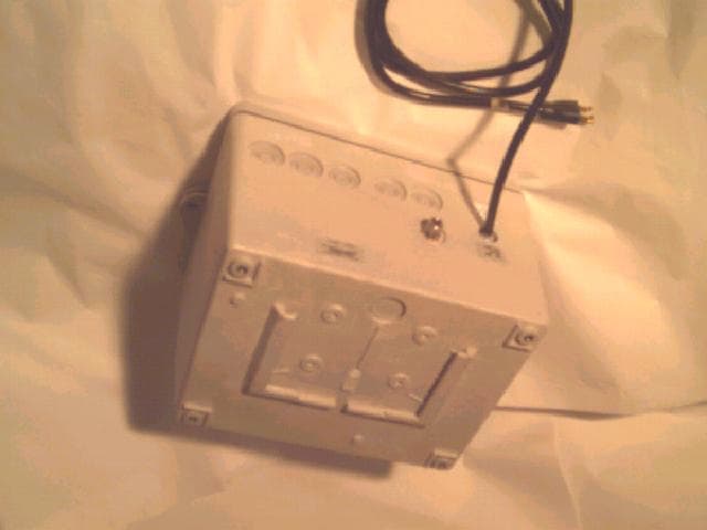
Click to zoom
Application Details
- Equipment Class
- TNB - Licensed Non-Broadcast Station Transmitter
- Date of Grant
- Oct 02, 2000
- Application Purpose
- Original Equipment
- Date of Application
- May 12, 2000
- Equipment Note
- Moscad-L P44-UHF FLN5923A, SCADA Terminal
- Frequency Range
- 403.00000000 - 433.00000000
- Company
- Motorola Solutions, Inc.
- Country
- United States
Documents & Files
Document Text
Text extracted from the exhibit documents filed with the FCC. Open a document above to read the original.
Users Manual
ToolBox for MOSCAD RTUs For Programming ToolBox Version 7.51 Motorola Inc.1999 All rights reserved System Overview 68P02956C45-A COMMERCIAL WARRANTY (STANDARD) Motorola radio communications products are warranted to be free from defects in material and workmanship for a period of ONE (1) YEAR, (except for crystals and channel elements which are warranted for a period of ten (10) years), from the date of shipment. Parts, including crystals and channel elements, will be replaced free of charge for the full warranty period but the labor to replace defective parts will only be provided for one Hundred-Twenty (120) days from the date of shipment. Thereafter purchaser must pay for the labor involved in repairing the product or replacing the parts at the prevailing rates together with any transportation charges to or from the place where warranty service is provided. This express warranty is extended by Motorola Communications and Electronics Inc., 1301 E. Algonquin Road, Schaumburg, Illinois 60196, to the original purchaser only, and only to those purchasing for purpose of leasing or solely for commercial, industrial, or governmental use. THIS WARRANTY IS GIVEN IN LIEU OF ALL OTHER WARRANTIES EXPRESS OR IMPLIED WHICH ARE SPECIFICALLY EXCLUDED, INCLUDING WARRANTIES OF MERCHANTABILITY OR FITNESS FOR A PARTICULAR PURPOSE. IN NO EVENT SHALL MOTOROLA BE LIABLE FOR INCIDENTAL OR CONSEQUENTIAL DAMAGES TO THE FULL EXTENT SUCH MAY BE DISCLAIMED BY LAW. In the event of a defect, malfunction or failure to conform to specifications established by seller, or if appropriate, to specifications accepted by Seller in writing, during the period shown, Motorola, at its option, will either repair or replace the product or refund the purchase price thereof, and such action on the part of Motorola shall be the full extent of Motorola’s liability hereunder. This warranty is void if: a.the product is used in other than its normal and customary manner; b.the product has been subject to misuse, accident neglect or damage; c.unauthorized alterations or repairs have been made, or unapproved parts used in the equipment. This warranty extends only to individual products, batteries are excluded, but carry their own separate limited warranty. Because each radio system is unique, Motorola disclaims liability for range, coverage, or operation of the system as a whole under this warranty except by a separate written agreement signed by an officer of Motorola. Non-Motorola manufactured products are excluded from this warranty, but subject to the warranty provided by their manufacturers, a copy of which will be supplied to you on specific written request. In order to obtain performance of this warranty, purchaser must contact its Motorola salesperson or Motorola at the address first above shown, attention Quality Assurance Department. This warranty applies only within the United States. COMPUTER SOFTWARE COPYRIGHTS The Motorola products described in this instruction manual may include copyrighted Motorola computer programs stored in semi conductor memories or other media. Laws in the United States and other countries preserve for Motorola certain exclusive rights for copyrighted computer programs including the exclusive right to copy or reproduce in any form the copyrighted computer program. Accordingly, any copyrighted Motorola computer programs contained in the Motorola products described in this instruction manual may not be copied or reproduced in any manner without the express written permission of Motorola. Furthermore, the purchase of Motorola products shall not be deemed to grant either directly or by implication, estoppel, or otherwise, any license under the copyrights, patents or patent applications of Motorola, except for the normal non-exclusive, royalty free license to use that arises by operation of law in the sale of a product. i Table of Contents GENERAL..............................................................................................................................................................III Glossary ...........................................................................................................................................................iii Terms and Conventions....................................................................................................................................vi MOSCAD RTU And ToolBox Software Version Policy ...................................................................................vii Applicable Documentation...............................................................................................................................viii Model Complements.........................................................................................................................................ix Options .............................................................................................................................................................x Accessories.......................................................................................................................................................xi T HEMOSCAD SYSTEM-OVERVIEW...................................................................................................................1 The MOSCAD System ......................................................................................................................................1 Control Center .............................................................................................................................................................. 1 Remote Terminal Unit (RTU)....................................................................................................................................... 2 Communication Processor/MODBUS (MCP-M) ......................................................................................................... 2 Communication Processor/TCP/IP (MCP-T)......…
Text truncated - open the document above for the full version.
Users Manual
MOTOROLA INC. FCC ID: AZ4FLN2583A Created by Ishay Kokavka 10/2/00 Page 1 of 6 Motorola confidential property EXHIBIT 8A 1 MOBAT RADIO (P44) 1 Radios spec (data sheet)....................................................................2-3 2 Pin configuration ...............................................................................4 3 Operating method ( siganls ....)...........................................................5-6 MOTOROLA INC. FCC ID: AZ4FLN2583A Created by Ishay Kokavka 10/2/00 Page 2 of 6 Motorola confidential property EXHIBIT 8A 2 1 Radios spec (data sheet ) 1.1 Introduction The P44 MOBAT radio is a mounted, stand alone, 7 channels UHF/VHF RF board which will be mounted on the MOSCAD_L (Or Moscad by a Sabonia) by means of an interface piggyback, for communication via port 3. 1.2 P44 Radio types. The P44 Types of Radios is shown in table 1.1 below. P44- UHF1 FLN2582A P44- UHF21 FLN2583A P44- VHF1 FLN2584A P44- VHF2 FLN2585A Channel BW 6.25,12.5,25 Khz 6.25,12.5,25 Khz 6.25,12.5,25 Khz 6.25,12.5,25 Khz Frequency 438-470 MHz403 – 433 MHz 136 - 155 MHz146 - 174 MHz Table 1.1 P44 Types of Radios. The marked radios are the radios that will be tested (UHF). 1.3 P44 Spec The P44 Spec is shown in table 1.2 below. GENERAL P44 UHF/VHF 12.5kHz Channel BW Synthesizer Reference 2.1,2.225,2.4 Mhz Channel Spacing 12.5Khz / 25Khz (6.25 capable) Operating Temperature - 30C to +60C Operating Mode Simplex / Half Duplex Supply Voltage -1 (Main) 7.5V +/-1.5V DO-13.8V+/-20% MOTOROLA INC. FCC ID: AZ4FLN2583A Created by Ishay Kokavka 10/2/00 Page 3 of 6 Motorola confidential property EXHIBIT 8A 3 Supply Voltage -2 5V +/-5% RF Connector RF Micro Jack Interface Connector 14-pin In-Line socket on 0.100 inch Synthesizer Data Load Time 98 bits in 48 microseconds minimum Dimensions 3.3"L x 2.25" W x 0.49" H Transmitter RF Power Out 1-5 Watt (Adjustable) Conducted Spurs - 38dbm Frequency Stability 2.5ppm (1.5ppm Optional) FM Hum and Noise 40dB Modulation Sensitivity 175 mV RMS/Khz 100 mV RMS/Khz Nominal Switching Bandwidth 32Mhz Audio Input DC Level 2.5 VDC Audio Distortion In what frequency response? <3% Attack Time What it means ? 12mSec (7mSec Typical) Typical Current Drain 2A @ 5Watt Max 1.4A @ 14V , 5Watt Max 2A @ 7.5V , 5Watt Receiver Sensitivity 0.38uV / 12dB SINAD Frequency Stability 2.5ppm (1.5ppm Optional) Selectivity 60 dB Intermodulation 60 dB Spurious Rejection 70 dB Image Rejection 70 dB FM Hum and Noise 48dB Frequency Response Flat +/- 2 dB from DC to 5kHz Audio Output :AC Level 70 mV RMS/Khz 100 mV RMS/Khz Nominal Audio Output :DC Level 2.5VDC Audio Response Flat Audio Distortion In what frequency response ? <5% Carrier Detect Attack Time Is it RSSI or CSQ ? 25 mSec Current Drain ~47 mA Turn Around Time 7 mSec Typical Switching Bandwidth 32 Mhz RSSI 0.5 to 1.9 V monotonically (20mV/dB) Conducted Spurs - 57dbm Group Delay Distortion <30uSec MOTOROLA INC. FCC ID: AZ4FLN2583A Created by Ishay Kokavka 10/2/00 Page 4 of 6 Motorola confidential property EXHIBIT 8A 4 < 20uSsc 2 Pin configuration of P44 radio is shown in table 2.1 below PIN No.Signal Name 1GNDReference node for all receive transmit and power signals. Proper grounding requires metal screws in the four corners mounted to a common chassis. 2SW_B+ Transmit - Max 2A @ 7.5VDC @ 5 Watt Receive - 47mA @ 7.5VDC 3XMIT_B+This signal is Asserted only during transmit time . 250 mA @ 7.5VDC 4RX_5VNot Connected 5TX_5VAsserted during Transmit - 40Ma @ 5VDC 6MODE_INAnalog data in to the radio to be transmitted. DC coupled with a nominal bias of 2.5VDC. 7SQ_DETOutput signal from the radio indicating that there is a valid RF signal on the channel 8ResetThis pin in pulled up in the radio. In normal mode must kept up. Used when programming the radio. 9RSSIOutput signal from the radio. The Volt level of this pin is according to the RF level of the received signal. 10Audio_OutReceived analog data is transferred to the CPU via this pin. 11CH_SEL_BChannel select pin (1 out of 7) 12CH_SEL_AChannel select pin (1 out of 7) 13CH_SEL_CChannel select pin (1 out of 7) 14CH_SEL_DChannel select pin (1 out of 7) Table 2.1 pin configuration of P44 radio. MOTOROLA INC. FCC ID: AZ4FLN2583A Created by Ishay Kokavka 10/2/00 Page 5 of 6 Motorola confidential property EXHIBIT 8A 5 3 Operating method ( siganls ....) 3.1 TIMING DIAGRAMS Figure 3 shows the timing diagrams of the MOBAT radio in transients between transmit and receive modes as it will be used with the MOSCAD_L. Timing Diagram Receive Transmit Receive Xmit_B+ Tx_5V FIGURE 3.1 TIMMING DIAGRAM 3.2 Channel Change The radio can operate in multi channel mode and single channel mode and is programmable via the RSS software of Mobat. 3.2.1 Single Channel In this mode only channels 1, and 2 are operational. CH_SEL_A is 0VDC Channel 1 is selected CH_SEL_A is 5VDC Channel 2 is selected When this signal is changed an interrupt is generated on the radio and the channel is changed. MOTOROLA INC. FCC ID: AZ4FLN2583A Created by Ishay Kokavka 10/2/00 Page 6 of 6 Motorola confidential property EXHIBIT 8A 6 3.2.2 Multi channel The channel of the radio is determined by the three channel select bits CH_SEL_BCH_SEL_CCH_SEL_DChannel selected 0001 1002 0103 1104 0015 1016 0117 Changing a channel could be done only in receive mode. After setting CH_SEL_B – CH-SEL_D reset CH_SEL_A for 5mS and assert it again. Channel select Timing Valid CH_SEL_B - CH_SEL_D Xmit_B+ Tx_5V 5 Ms CH_SEL A
Attestation Statements
MOTOROLA INC. FCC ID: AZ4FLN2583A EXHIBIT 2 SHEET 1 OF 1 CERTIFICATION OF DATA The technical data supplied with this application, having been taken under my supervision and is hereby duly certified. The following is a statement of my qualifications: 1) I have received a BASc degree in Electrical Engineering from University of British Columbia, Canada, in 1986. 2) I have 10 years experience in developing, testing and certifying electronics and communication products. NAME: Robert E. Stirling, P.Eng. SIGNATURE: Robert E. Stirling DATE: April 8, 2000 POSITION: Director, Senior Engineer, Protocol Labs FCC Registration number: 96437
Attestation Statements
MOTOROLA INC. FCC ID: AZ4FLN2583A EXHIBIT 11 SHEET 1 OF 1 RF EXPOSURE INFORMATION This base station is a fixed transmitter, and is exempt from routine environmental evaluation for RF exposure in accordance with 47 CFR 2.1091 and 47 CFR 2.1093.
Block Diagram
MOTOROLA INC. FCC ID: AZ4FLN2583A EXHIBIT 4 SHEET 1 OF 2 CIRCUIT DESCRIPTIONS EXHIBIT 4A – MEANS FOR FREQUENCY STABILIZATION Frequency stabilization is achieved with a temperature compensated crystal oscillator ,u712. Temperature stabilization is accomplished with a compensating network included in an integrated circuit. The resistors in the compensating network are lasers trimmed to the value determined by the specific value required in the temperature run. The reference oscillator frequency is 16.8Mhz. EXHIBIT 4B – MEANS FOR LIMITING MODULATION Electronic attenuator that located in the synthesizer IC u251 is controlled by the radio microprocessor, u717, To limit the deviation and to keep the deviation constant over the RF frequency range & channel bandwidth, the microcomputer adds the proper correction factor to the attenuator. EXHIBIT 4C – MEANS FOR ATTENUATION OF HIGHER AUDIO FREQUENCIES The output of the limiter is applied to a low-pass filter. This filter corner located at 6000 Hz. The output of the low-pass filter is applied to the modulator located in the synthesizer VCO and driving a varactor cr255. EXHIBIT 4D – MEANS FOR ATTENUATION OF SPURIOUS EMISSIONS The final stage of the RF power amplifier circuit feeds a low-pass filter in order to attenuate Harmonics of the carrier frequency as well as any spurious signals. The filter is a seven-pole Elliptic design using LC elements. A cast metal compartmentalized shielded enclosure is placed over the main circuit RF board and secured to the chassis with screws. This technique provides very effective and reliable shielding of the various circuits on the main board from each other and from the external environment, minimizing spurious RF radiated emissions. EXHIBIT 4E – MEANS FOR LIMITING OUTPUT POWER Output power is regulated through the use of a current sensing ALC loop. The voltage across voltage sensing coupler u714 provides a feedback signal to the Power Control IC U715. This signal is then compared to the preprogrammed voltage reference and the error Signal is amplified and used to generate a control voltage to control the bias of the PA Stage U713. EXHIBIT 4F – MODULATION TECHNIQUES The transmitter is capable of the following types of modulation: 1. DPSK 1200 BPS 2. FSK 2400 BPS 3. DFM 4800 BPS 4. Dual Binary (COS) 9600 BPS The modulation signal is processed through the limited attenuator and low pass filter. The The microcomputer adjusts the attenuator to compensate for modulation sensitivity variations of the synthesizer. MOTOROLA INC. FCC ID: AZ4FLN2583A EXHIBIT 4 SHEET 2 OF 2 EXHIBIT 4G – MEANS FOR CONTROLLING TRANSIENT FREQUENCY BEHAVIOR The effects of VCO frequency shifts due to transmitter key-up and de-key impedance variations are minimized through the use of a multiple-stage transmitter lineup with resistive isolation pads between various stages, including a pad between the output of the VCO buffer amplifier circuit and the input of the transmitter circuit. Additionally, the value of the reference voltage which controls output power is gradually raised during transmitter key-up and lowered during de-key, shaping the transmitter attack and decay characteristics by gradually changing the power control voltage.
Cover Letter(s)
MOTOROLA INC.FCC ID: AZ4FLN2583A Radio Products Group EXHIBIT 13 8000 West Sunrise Boulevard, Fort Lauderdale, Florida 33322. (954) 723-5000 SHEET 1 OF 1 May 12, 2000 Authorization & Evaluation Di vision Federal Communications Commission Laboratory 7435 Oakland Mills Road Columbia, MD 21046 Subject: Application for Certification of Transmitter with FCC ID: AZ4FLN2583A Attention: Mr. Frank Coperich, Mr. George Tannahill. Gentlemen: Motorola Communication, Kerminitzki 3 TelAviv, Israel, herein submits this application for Certification of the subject transmitter. This transmitter is intended for use in a base station environment with capabilities for data communications with a variable transmit power of 0.25 to 4Watt. The subject transmitter complies with Section 90.203 of the Rules in that the operator cannot directly program transmit frequencies using the unit's normally accessible external controls. A complete Certification application is enclosed, contact Rob Stirling at (604) 218 1762 for testing details, or Mr. Mike Ramnath at (954)723-793 or Fax (954)723-4794 if you require any informat ion about the submission. Sincerely, Rob Stirling, P.Eng EMAIL [email protected]
Cover Letter(s)
MOTOROLA INC.FCC ID: AZ4FLN2583A Radio Products Group EXHIBIT 13 8000 West Sunrise Boulevard, Fort Lauderdale, Florida 33322. (954) 723-5000 SHEET 1 OF 1 May 31, 2000 Authorization & Evaluation Division Federal Communications Commission Laboratory 7435 Oakland Mills Road Columbia, MD 21046 Subject: Part Number and FCC ID Changes for Certification of our base station transmitter, Model P44-UHF2 FLN2583A with FCC ID: AZ4FLN2583A Attention: Mr. Frank Coperich, Mr. George Tannahill. Gentlemen: We would hereby like to request a change to the noted transmitter model number, part number and FCC ID in the pending application. The unit Model Number is F6838A, The radio module part number is FRN5923A, and the new requested FCC ID would be AZ489FT4839 . Label artwork and placement photos are enclosed in the submission, please feel free to contact me at (604) 218 1762 or the following EMAIL address. Sincerely, Rob Stirling, P.Eng EMAIL [email protected]
Cover Letter(s)
EXHIBIT 13b September 26, 2000 Mr. Frank Coperich Authorization & Evaluation Division Federal Communications Commission Laboratory 7435 Oakland Mills Road Columbia, MD 21046 Subject: Response to Correspondence Number 16221 for Pending Certification application with FCC ID: AZ4FLN2583A and Confirmation Number EA97579. Dear Mr. Coperich: Protocol Labs on behalf of Motorola, Inc. is responding to the correspondence number 16221. We are also requesting, per our telephone discussion, a change in the FCC identifier from FCC ID: AZ4FLN2583A to FCC ID: AZ489FT4839 and a modification to the transmitter model number information that would be listed in the “notes” section of the Grant for Equipment Authorization. The model number information should be listed as follows: “Moscad-L P44-UHF FLN5923A, SCADA Terminal” We respectfully agree with the Commission’s recommendations and are dropping our request for an F2D Emission Designator. In addition, we ask the Commission to add the following Emission Designators to the application: 11K2F3D, 11K2F1D and 11K2DXW. We trust that the above information satisfies your requirements. If you have any questions, you may contact me at (604) 218-1762. Sincerely, Rob Stirling, P.Eng EMAIL [email protected]
External Photos
MOTOROLA INC. FCC ID: AZ4FLN2583A EXHIBIT 3 SHEET 1 OF 2 EXHIBIT 3: EXTERNAL PHOTOS MOSCAD-L FRONT VIEW MOTOROLA INC. FCC ID: AZ4FLN2583A EXHIBIT 3 SHEET 2 OF 2 MOSCAD-L REAR-BOTTOM VIEW
ID Label/Location Info
MOTOROLA INC. FCC ID: AZ4FLN2583A EXHIBIT 1 Page 1 of 3 LIST OF EXHIBITS DESCRIPTION EXHIBIT REFERENCE I. Identification label information1 & General Information1a 1. Production Plans 2. Data Submittal Procedure2.1061 II. Certification of Data2 III. External Photographs32.1033 IV. Circuit Descriptions4 V. Schematic Diagrams52.1033 VI. Test Report6 1. Data Index6 2. RF Output Data6A2.1046 3. Occupied Bandwidth6B2.1049(i) 4. Conducted Spurious Emissions6C2.1051 6. Powerline Conducted Spurious Emissions6D15.208 6. Radiated Spurious Emissions6E2.1053, 15.209 7. Frequency Stability, Transient Behavior6F2.1047, 90.213, 90214 (Temperature & Supply Voltage) VII. Test Set-up Procedures7 VIII. Instruction Manual8 IX. Internal Photographs.9 2.1033 X. Parts List and Tune-Up procedures10 XI. RF Exposure Information112.1091, 2.1093 XII. Operational Description12 1. Technical Characteristics 2. Application XIII. Cover Letter13 MOTOROLA INC. FCC ID: AZ4FLN2583A EXHIBIT 1 Page 2 of 3 LOCATION A nameplate of the type presented below will be affixed to every transmitter. It will be placed on the outside of the housing at the bottom back of the transmitter. TYPE The label is a paper polyester film laminate with a pressure sensitive adhesive backing. The adhesive is a permanent type acrylic with a minimum peel strength of 40 oz/inch. Label Text Model: P44- UHF2 FLN2583A FCC ID: AZ4FLN2583A Made in Israel by MOTOROLA INC. MOTOROLA INC. FCC ID: AZ4FLN2583A EXHIBIT 1 Page 3 of 3 EXHIBIT 1A - GENERAL INFORMATION 1. Production Plans Quantity production is planned. 2. Data Submittal Procedure: Data is supplied in accordance with Part 2, Sub-part J of the Commissions’ rules. The intended use of this transceiver includes applications covered in the Code of Federal Regulations Title 47, Parts 15 and 90. Transmitter power shall not exceed 4 watts and this power level shall not be adjustable by the user.
ID Label/Location Info
MOTOROLA INC.FCC ID: AZ489FT4839 Radio Products Group EXHIBIT 1 8000 West Sunrise Boulevard, Fort Lauderdale, Florida 33322. (954) 723-5000 SHEET 1 of 3 Sample Label Artwork MOTOROLA INC.FCC ID: AZ489FT4839 Radio Products Group EXHIBIT 1 8000 West Sunrise Boulevard, Fort Lauderdale, Florida 33322. (954) 723-5000 SHEET 2 of 3 FCC ID Label location MOTOROLA INC.FCC ID: AZ489FT4839 Radio Products Group EXHIBIT 1 8000 West Sunrise Boulevard, Fort Lauderdale, Florida 33322. (954) 723-5000 SHEET 3 of 3 FCC Warning Label location
Internal Photos
MOTOROLA INC. FCC ID: AZ4FLN2583A EXHIBIT 9 SHEET 1 OF 5 EXHIBIT 9: INTERNAL PHOTOS MOSCAD-L INTERIOR VIEW MOTOROLA INC. FCC ID: AZ4FLN2583A EXHIBIT 9 SHEET 2 OF 5 MOSCAD-L COMMUNICATION MODULE REAR VIEW MOTOROLA INC. FCC ID: AZ4FLN2583A EXHIBIT 9 SHEET 3 OF 5 MOSCAD-L COMMUNICATION MODULE FRONT VIEW MOTOROLA INC. FCC ID: AZ4FLN2583A EXHIBIT 9 SHEET 4 OF 5 MOSCAD-L COMMUNICATION MODULE REAR VIEW MOTOROLA INC. FCC ID: AZ4FLN2583A EXHIBIT 9 SHEET 5 OF 5 MOSCAD-L RF MODULE CONSTRUCTION
Operational Description
MOTOROLA INC.FCC ID: AZ4FLN2583A EXHIBIT 12 SHEET 1 OF 2 OPERATIONAL DESCRIPTION P44- UHF2 FLN2583A I. Transmitter Technical Characteristics A. Specific Operating Power Levels: RATED: 0.25 to 4 Watts, variable, not user adjustable MEASURED: Refer to Exhibit 6A Maximum Power Rating: 4 Watts Means provided for variation of operating power: Factory set or performed by authorized personnel using published Tune-up Procedure B. Frequency Range: 403-433 MHz C. Frequency Stability: RATED: ± 0.00025% (± 2.5 ppm) MEASURED: Refer to Exhibits 6F-1 and 6F-2. D. Types of Emissions: F2D Data Radio E. Spurious Emissions: RATED: 1.39 uW (-58.6 dBm) maximum, which corresponds to –54.9 dBc at 4.0 Watt setting. Refer to Exhibit 6E. F. DC Operating Voltages and Currents: Refer to Exhibit 6A. II. Transmitter Application The following features, options, accessories, and installations characterize the transmitter. A. Power Supply: 115 Vac (Nominal) or 12 Vdc battery (backup) B. Antenna External 50-ohm antenna, Type-N Connector provided MOTOROLA INC.FCC ID: AZ4FLN2583A EXHIBIT 12 SHEET 2 OF 2 C. Transmission Modes DPSK 1200 BPS FSK 2400 BPS DFM 4800 BPS Dual Binary (COS) 9600 BPS D. Maximum Transmit Channel Capability: 1 Channel, 12.5 Channel Bandwidth, Full Duplex E. Housing Style: The transmitter assembly is shielded with a metal can and is mounted on the communication module of the MOSCAD-L can as shown in the accompanying photographs. The communication module is housed in the MOSCAD-L Plastic Chassis. The transmitter circuitry is contained on a single printed circuit board that is mounted inside the metal can on a carrier board, and secured to it with screws. A fitted cover completes the shielding enclosure, as shown in the accompanying photographs. F. Programmability: Programming is accomplished by the use of an IBM PC computer or through a link with another terminal, using the MOSCAD-L Toolbox Software. This provides means for adjustment of the transmitter, including programming of the channel frequencies, communication protocols and data rates. NOTE: The transmitter power is NOT programmable by the operator.
Parts List/Tune Up Info
MOTOROLA INC.FCC ID: AZ4FLN2583A EXHIBIT 10 PAGE 1 of 21 MoBat Wireless application Proceed. No: 12MB000004 Issue:O Date:07/99 MATERIAL or METHODS SPECIFICATION Assembly name : P42/44 UHF For customer use Kits : FRN5916/17 P42 FRN5922/23 P44 O Rev.ECN No.Apvrd byQ.A.Date Page123456789101112131415161718192021 IssueOOOOOOOOOOOOOOOOOOOO Page222324252627282930313233343536373839404142 Issue00 Approvals : Written by Yehuda Eder signature :Date ______ Approved by signature :Date :______ Quality Assurance Sofersignature :Date :______ MOTOROLA INC.FCC ID: AZ4FLN2583A EXHIBIT 10 PAGE 2 of 21 TABLE OF CONTENTS 1. SPECIFICATIONS ...................................... 3 1.1 Introduction .................................. 3 1.2 Detailed Technical Specification .............. 3 1.2.1 General ................................ 3 1.2.2 Transmitter ............................ 4 1.2.3 Receiver ............................... 4 1.2.4 Power Supply ........................... 6 1.2.5 Environmental .......................... 7 2.TEST EQUIPMENT & PROGRAMS ............................ 8 RADIO ADJUSTMENTS - GENERAL ......................... 10 2.1.TRANSMITTER CALIBRATION ....................... 10 2.2.RECEIVER CALIBRATION .......................... 12 3.RECEIVE FINAL TEST SPECIFICATIONS .................... 15 3.1. Sensitivity/Selectivity .................... 15 3.1.1.12 dB Sinad ............................ 15 3.1.2. Adjacent channel selectivity .......... 16 3.1.3. spurious response rejection 3.1.4. Intermodulation response rej. ....... 16 3.2.DISC Output and Distortion .................... 16 3.3.RX Hum and Noise .............................. 17 3.4.Receiver Audio Frequency Response ............. 17 3.5.RSSI .......................................... 18 3.6.Standby Current Drain ......................... 18 4.TRANSMIT FINAL TEST SPECIFICATIONS ................... 19 4.1.Transmitter Frequency Accuracy ................ 19 4.2.RF Power Output ............................... 19 4.3.Transmitter Current Drain ..................... 20 4.4.Modulation Sensitivity (Deviation) ............ 20 4.5.Transmitter Distortion ........................ 21 4.6.Tx Hum and Noise .............................. 21 4.7.Transmitter Audio Frequency Response .......... 22 4.8.Transmitter attack time. . . . 4.9.Transmitter Spurious emissions 5. P44/P42 INTERFACE ................................... 23 MOTOROLA INC.FCC ID: AZ4FLN2583A EXHIBIT 10 PAGE 3 of 21 1. SPECIFICATIONS 1.1 Introduction The P42/44 UHF are a radio tranceivers module that is intended to be a subassembly in terminals products. The radio covers the tranceivers frequency ranges of 403-433Mhz and 438-470Mhz the at 12.5KHz channel spacing. It includes no voice processing circuitry and is optimized for dataoperation. The purpose of this document is to define the performance requirements for the UHF radios. 1.2 Detailed Technical Specification All specifications will be met over the temperature range of -30 to +60 degree C at the supply 7.5 volt DC. 1.2.1 General Frequency rangeFRN5916/7 p42 403-433Mhz/438-470Mhz FRN5922/23 p44 403-433Mhz/438-470Mhz ModulationFM Antenna Impedance50 ohms Frequency stability2.5 ppm Duty Cycle Normal opration : Maximum Rating : 20% Tx 80% Rx - 10 Sec Tx., 40 Sec Rx. Continuous transmission should not exceed 25 seconds. MOTOROLA INC.FCC ID: AZ4FLN2583A EXHIBIT 10 PAGE 4 of 21 1.2.2 Transmitter RF Output - High power:4W min. at room temperature and 7.5 VDC +2/-3 dB from -30 to 70 degree C 6 to 9 VDC Measured per EIA RS-152-B section 3 Conducted Spourious:-60dBc non-harmonic -60 dBc harmonic Measured per EIA RS-152-B section 4 Radiated Spourious:500uV/m at 3 m Measured per FCC Part 15. Audio Frequency Response:3Hz to 5KHz ; +/- 2dB Measured per Section 5.7 in this spec. Distortion:5% Measured per Section 5.5 in this spec. Hum and Noise25 dB Measured per Section 5.6 in this spec. MOD Input sensitivity350mVrms/ +/-2khz dev +/-0.5dB Measured per Section in this spec. Modulation Stability+/-10% Measured per Section 5.4 in this spec. Tx Turn-on Time:10 msec. MOTOROLA INC.FCC ID: AZ4FLN2583A EXHIBIT 10 PAGE 5 of 21 Transmit Current2.5A Frequency Stability2.5ppm MOTOROLA INC.FCC ID: AZ4FLN2583A EXHIBIT 10 PAGE 6 of 21 1.2.3 Receiver Receiver Sensitivity 12 dB Sinad-113dBm Measured per RS-204-C Paragraph 7.0 with external de-emphasis network. Adjacent Channel Selectivity 60dB Measured per RS-204-C Paragraph 12.0 with external de-emphasis Spurious and Image60dB Measured per RS-204-C Paragraph Intermodulation 60dB Measured per RS-204-C Paragraph 14.0 with external de-emphasis network. Conducted Spurious Emission-57dBm Measured per RS-204-C Paragraph 16.0 . Audio Frequency Response3 Hz to 5 KHz +/-2dB Measured per Section 4.4 in this spec. Distortion5% Measured per Section 4.2 in this spec. Hum and Noise25dB Measured per Section 4.3 in this spec. DISC Output Stability +/- 10% Measured per Section 4.2 in this spec. RSSI OutputSee Figure 7.1 Measured per Section 4.5 in this spec. Receiver settling Time10 msec. Measured per APPENDIX I, Section 4 Receiver Settling Time From Battery Save Mode to fully operation10 msec Measured per APPENDIX I, Section 5 1.2.4 Power Supply ... Nominal Voltage7.5 volts DC Operational Voltage Range6 to 9 volts DC PolarityNegative Ground Current Drain : Battery Save Mode:10mA Receiver :50mA MOTOROLA INC.FCC ID: AZ4FLN2583A EXHIBIT 10 PAGE 7 of 21 Transmit : 2.5A@4watt MOTOROLA INC.FCC ID: AZ4FLN2583A EXHIBIT 10 PAGE 8 of 21 1.2.5 Enviromental Temperature : The radio will operate and meet the stated specifications from -30 to +60 degree C. Storage temperature -40 to +80 degree C. Humidity : 95% humidity at +50 degree C, 63.5 hrs exposed. Vibrations and Shock : Per EIA RS152B MDI doc #910,0436, Survival four foot drop on concrete when i…
Text truncated - open the document above for the full version.
Contact Information
Applicant
Deanna Zakharia(Regulatory Compliance Manager)
Technical Contact
Protocol LabsRobert E Stirling
[email protected]604 218 1762
28945 McTavish Rd. · Abbotsford, BC · Canada
Non-Technical Contact
Motorola Radio Products GroupMike Ramnath
[email protected](954)723-793
Test Firm
Protocol LabsRobert Stirling
Technical Specifications
| # | Rule Parts | Frequency Range | Power Output | Emission | Tolerance |
|---|---|---|---|---|---|
| 3 | 9 | 403 MHz - 433 MHz | 4 W | 11K2DXW | 1.5 ppm |
Other Applications from Motorola Solutions, Inc.

AZ489FT4980
Sep 08, 2026Portable two way radio
Equipment Class
TNF - Licensed Non-Broadcast Transmitter Held to FaceAZ489FT4981
Aug 14, 2026Handheld Portable - TANAPA BPR 45 400-470 MHZ 4W NKP
Equipment Class
TNF - Licensed Non-Broadcast Transmitter Held to Face
AZ489FT7187
Jul 13, 2026Portable 2-Way Radio with Bluetooth, Bluetooth LE, WIFI 2.4GHz, WIFI 5GHz, LTE
Equipment Class
DSS - Part 15 Spread Spectrum TransmitterAZ499FT6031
May 11, 2026Operation Critical Wireless Earpiece PTT
Equipment Class
DSS - Part 15 Spread Spectrum Transmitter
AZ499FT5879
Dec 19, 20252-way Portable Radio with BT, BTLE, WIFI, NFC and LTE
Equipment Class
DSS - Part 15 Spread Spectrum Transmitter