AZ489FT4840MOSCAD-L P44-UHF1 FLN2582A , SCADA Terminal
Motorola Solutions, Inc.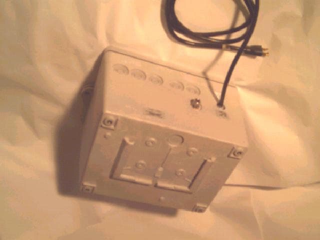
Click to zoom
Application Details
- Equipment Class
- TNB - Licensed Non-Broadcast Station Transmitter
- Date of Grant
- Jul 16, 2000
- Application Purpose
- Original Equipment
- Date of Application
- May 12, 2000
- Equipment Note
- MOSCAD-L P44-UHF1 FLN2582A , SCADA Terminal
- Frequency Range
- 438.00000000 - 470.00000000
- Company
- Motorola Solutions, Inc.
- Country
- United States
Documents & Files
Document Text
Text extracted from the exhibit documents filed with the FCC. Open a document above to read the original.
Users Manual
ToolBox for MOSCAD RTUs For Programming ToolBox Version 7.51 Motorola Inc.1999 All rights reserved System Overview 68P02956C45-A COMMERCIAL WARRANTY (STANDARD) Motorola radio communications products are warranted to be free from defects in material and workmanship for a period of ONE (1) YEAR, (except for crystals and channel elements which are warranted for a period of ten (10) years), from the date of shipment. Parts, including crystals and channel elements, will be replaced free of charge for the full warranty period but the labor to replace defective parts will only be provided for one Hundred-Twenty (120) days from the date of shipment. Thereafter purchaser must pay for the labor involved in repairing the product or replacing the parts at the prevailing rates together with any transportation charges to or from the place where warranty service is provided. This express warranty is extended by Motorola Communications and Electronics Inc., 1301 E. Algonquin Road, Schaumburg, Illinois 60196, to the original purchaser only, and only to those purchasing for purpose of leasing or solely for commercial, industrial, or governmental use. THIS WARRANTY IS GIVEN IN LIEU OF ALL OTHER WARRANTIES EXPRESS OR IMPLIED WHICH ARE SPECIFICALLY EXCLUDED, INCLUDING WARRANTIES OF MERCHANTABILITY OR FITNESS FOR A PARTICULAR PURPOSE. IN NO EVENT SHALL MOTOROLA BE LIABLE FOR INCIDENTAL OR CONSEQUENTIAL DAMAGES TO THE FULL EXTENT SUCH MAY BE DISCLAIMED BY LAW. In the event of a defect, malfunction or failure to conform to specifications established by seller, or if appropriate, to specifications accepted by Seller in writing, during the period shown, Motorola, at its option, will either repair or replace the product or refund the purchase price thereof, and such action on the part of Motorola shall be the full extent of Motorola’s liability hereunder. This warranty is void if: a.the product is used in other than its normal and customary manner; b.the product has been subject to misuse, accident neglect or damage; c.unauthorized alterations or repairs have been made, or unapproved parts used in the equipment. This warranty extends only to individual products, batteries are excluded, but carry their own separate limited warranty. Because each radio system is unique, Motorola disclaims liability for range, coverage, or operation of the system as a whole under this warranty except by a separate written agreement signed by an officer of Motorola. Non-Motorola manufactured products are excluded from this warranty, but subject to the warranty provided by their manufacturers, a copy of which will be supplied to you on specific written request. In order to obtain performance of this warranty, purchaser must contact its Motorola salesperson or Motorola at the address first above shown, attention Quality Assurance Department. This warranty applies only within the United States. COMPUTER SOFTWARE COPYRIGHTS The Motorola products described in this instruction manual may include copyrighted Motorola computer programs stored in semi conductor memories or other media. Laws in the United States and other countries preserve for Motorola certain exclusive rights for copyrighted computer programs including the exclusive right to copy or reproduce in any form the copyrighted computer program. Accordingly, any copyrighted Motorola computer programs contained in the Motorola products described in this instruction manual may not be copied or reproduced in any manner without the express written permission of Motorola. Furthermore, the purchase of Motorola products shall not be deemed to grant either directly or by implication, estoppel, or otherwise, any license under the copyrights, patents or patent applications of Motorola, except for the normal non-exclusive, royalty free license to use that arises by operation of law in the sale of a product. i Table of Contents GENERAL..............................................................................................................................................................III Glossary ...........................................................................................................................................................iii Terms and Conventions....................................................................................................................................vi MOSCAD RTU And ToolBox Software Version Policy ...................................................................................vii Applicable Documentation...............................................................................................................................viii Model Complements.........................................................................................................................................ix Options .............................................................................................................................................................x Accessories.......................................................................................................................................................xi T HEMOSCAD SYSTEM-OVERVIEW...................................................................................................................1 The MOSCAD System ......................................................................................................................................1 Control Center .............................................................................................................................................................. 1 Remote Terminal Unit (RTU)....................................................................................................................................... 2 Communication Processor/MODBUS (MCP-M) ......................................................................................................... 2 Communication Processor/TCP/IP (MCP-T)......…
Text truncated - open the document above for the full version.
Attestation Statements
MOTOROLA INC.FCC ID: AZ4FLN2582A EXHIBIT 2 SHEET 1 OF 1 CERTIFICATION OF DATA The technical data supplied with this application, having been taken under my supervision and is hereby duly certified. The following is a statement of my qualifications: 1) I have received a BASc degree in Electrical Engineering from University of British Columbia, Canada, in 1986. 2) I have 10 years experience in developing, testing and certifying electronics and communication products. NAME: Robert E. Stirling, P.Eng. SIGNATURE: Robert E. Stirling DATE: April 8, 2000 POSITION: Director, Senior Engineer, Protocol Labs FCC Registration number: 96437
Attestation Statements
MOTOROLA INC.FCC ID: AZ4FLN2582A EXHIBIT 11 SHEET 1 OF 1 RF EXPOSURE INFORMATION This base station is a fixed transmitter, and is exempt from routine environmental evaluation for RF exposure in accordance with 47 CFR 2.1091 and 47 CFR 2.1093.
Block Diagram
MOTOROLA INC.FCC ID: AZ4FLN2582A EXHIBIT 4 SHEET 1 OF 2 CIRCUIT DESCRIPTIONS EXHIBIT 4A – MEANS FOR FREQUENCY STABILIZATION Frequency stabilization is achieved with a temperature compensated crystal oscillator ,u712. Temperature stabilization is accomplished with a compensating network included in an integrated circuit. The resistors in the compensating network are lasers trimmed to the value determined by the specific value required in the temperature run. The reference oscillator frequency is 16.8Mhz. EXHIBIT 4B – MEANS FOR LIMITING MODULATION Electronic attenuator that located in the synthesizer IC u251 is controlled by the radio microprocessor, u717, To limit the deviation and to keep the deviation constant over the RF frequency range & channel bandwidth, the microcomputer adds the proper correction factor to the attenuator. EXHIBIT 4C – MEANS FOR ATTENUATION OF HIGHER AUDIO FREQUENCIES The output of the limiter is applied to a low-pass filter. This filter corner located at 6000 Hz. The output of the low-pass filter is applied to the modulator located in the synthesizer VCO and driving a varactor cr255. EXHIBIT 4D – MEANS FOR ATTENUATION OF SPURIOUS EMISSIONS The final stage of the RF power amplifier circuit feeds a low-pass filter in order to attenuate Harmonics of the carrier frequency as well as any spurious signals. The filter is a seven-pole Elliptic design using LC elements. A cast metal compartmentalized shielded enclosure is placed over the main circuit RF board and secured to the chassis with screws. This technique provides very effective and reliable shielding of the various circuits on the main board from each other and from the external environment, minimizing spurious RF radiated emissions. EXHIBIT 4E – MEANS FOR LIMITING OUTPUT POWER Output power is regulated through the use of a current sensing ALC loop. The voltage across voltage sensing coupler u714 provides a feedback signal to the Power Control IC U715. This signal is then compared to the preprogrammed voltage reference and the error Signal is amplified and used to generate a control voltage to control the bias of the PA Stage U713. EXHIBIT 4F – MODULATION TECHNIQUES The transmitter is capable of the following types of modulation: 1. DPSK 1200 BPS 2. FSK 2400 BPS 3. DFM 4800 BPS 4. Dual Binary (COS) 9600 BPS The modulation signal is processed through the limited attenuator and low pass filter. The The microcomputer adjusts the attenuator to compensate for modulation sensitivity variations of the synthesizer. MOTOROLA INC.FCC ID: AZ4FLN2582A EXHIBIT 4 SHEET 2 OF 2 EXHIBIT 4G – MEANS FOR CONTROLLING TRANSIENT FREQUENCY BEHAVIOR The effects of VCO frequency shifts due to transmitter key-up and de-key impedance variations are minimized through the use of a multiple-stage transmitter lineup with resistive isolation pads between various stages, including a pad between the output of the VCO buffer amplifier circuit and the input of the transmitter circuit. Additionally, the value of the reference voltage which controls output power is gradually raised during transmitter key-up and lowered during de-key, shaping the transmitter attack and decay characteristics by gradually changing the power control voltage.
Cover Letter(s)
MOTOROLA INC.FCC ID: AZ4FLN2583A Radio Products Group EXHIBIT 13 8000 West Sunrise Boulevard, Fort Lauderdale, Florida 33322. (954) 723-5000 SHEET 1 OF 1 April 12, 2000 Authorization & Evaluation Division Federal Communications Commission Laboratory 7435 Oakland Mills Road Columbia, MD 21046 Subject: Application for Certification of our base station transmitter, Model P44-UHF2 FLN2583A with FCC ID: AZ4FLN2583A Attention: Mr. Frank Coperich, Mr. George Tannahill. Gentlemen: Motorola Communication, Kerminitzki 3 TelAviv, Israel, herein submits this application for Certification of the subject transmitter. This transmitter is intended for use in a base station environment with capabilities for data communications with a variable transmit power of 0.25 to 4 Watt . The subject transmitter complies with Section 90.203 of the Rules in that the operator cannot directly program transmit frequencies using the unit's normally accessible external controls. A complete Certification application is enclosed, contact Rob Stirling at (604) 218 1762 for testing details, or Mr. Mike Ramnath at (954)723-793 or Fax (954)723-4794 if you require any informat ion about the submission. Sincerely, Rob Stirling, P.Eng EMAIL [email protected]
Cover Letter(s)
MOTOROLA INC.FCC ID: AZ4FLN2582A Radio Products Group EXHIBIT 13 8000 West Sunrise Boulevard, Fort Lauderdale, Florida 33322. (954) 723-5000 SHEET 1 OF 1 May 31, 2000 Authorization & Evaluation Division Federal Communications Commission Laboratory 7435 Oakland Mills Road Columbia, MD 21046 Subject: Part Number and FCC ID Changes for Certification of our base station transmitter, Model P44-UHF2 FLN2582A with FCC ID: AZ4FLN2582A Attention: Mr. Frank Coperich, Mr. George Tannahill. Gentlemen: We would hereby like to request a change to the noted transmitter model number, part number and FCC ID in the pending application. The unit Model Number is F6839A, The radio module part number is FRN5922A, and the new requested FCC ID would be AZ489FT4840. Label artwork and placement photos are enclosed in the submission, please feel free to contact me at (604) 218 1762 or the following EMAIL address. Sincerely, Rob Stirling, P.Eng EMAIL [email protected]
External Photos
MOTOROLA INC. FCC ID: AZ4FLN2582A EXHIBIT 3 SHEET 1 OF 2 EXHIBIT 3: EXTERNAL PHOTOS MOSCAD-L FRONT VIEW MOTOROLA INC. FCC ID: AZ4FLN2582A EXHIBIT 3 SHEET 2 OF 2 MOSCAD-L REAR-BOTTOM VIEW
ID Label/Location Info
MOTOROLA INC.FCC ID: AZ4FLN2582A EXHIBIT 1 Page 1 of 3 LIST OF EXHIBITS DESCRIPTION EXHIBIT REFERENCE I. Identification label information1 & General Information1a 1. Production Plans 2. Data Submittal Procedure2.1061 II. Certification of Data2 III. External Photographs32.1033 IV. Circuit Descriptions4 V. Schematic Diagrams52.1033 VI. Test Report6 1. Data Index6 2. RF Output Data6A2.1046 3. Occupied Bandwidth6B2.1049(i) 4. Conducted Spurious Emissions6C2.1051 6. Powerline Conducted Spurious Emissions6D15.208 6. Radiated Spurious Emissions6E2.1053, 15.209 7. Frequency Stability, Transient Behavior6F2.1047, 90.213, 90214 (Temperature & Supply Voltage) VII. Test Set-up Procedures7 VIII. Instruction Manual8 IX. Internal Photographs.9 2.1033 X. Parts List and Tune-Up procedures10 XI. RF Exposure Information112.1091, 2.1093 XII. Operational Description12 1. Technical Characteristics 2. Application XIII. Cover Letter13 MOTOROLA INC.FCC ID: AZ4FLN2582A EXHIBIT 1 Page 2 of 3 LOCATION A nameplate of the type presented below will be affixed to every transmitter. It will be placed on the outside of the housing at the bottom back of the transmitter. TYPE The label is a paper polyester film laminate with a pressure sensitive adhesive backing. The adhesive is a permanent type acrylic with a minimum peel strength of 40 oz/inch. Label Text Model: P44- UHF2 FLN2582A FCC ID: AZ4FLN2582A Made in Israel by MOTOROLA INC. MOTOROLA INC.FCC ID: AZ4FLN2582A EXHIBIT 1 Page 3 of 3 EXHIBIT 1A - GENERAL INFORMATION 1. Production Plans Quantity production is planned. 2. Data Submittal Procedure: Data is supplied in accordance with Part 2, Sub-part J of the Commissions’ rules. The intended use of this transceiver includes applications covered in the Code of Federal Regulations Title 47, Parts 15 and 90. Transmitter power shall not exceed 4 watts and this power level shall not be adjustable by the user.
ID Label/Location Info
MOTOROLA INC.FCC ID: AZ489FT4840 Radio Products Group EXHIBIT 1 8000 West Sunrise Boulevard, Fort Lauderdale, Florida 33322. (954) 723-5000 SHEET 1 of 3 Sample Label Artwork MOTOROLA INC.FCC ID: AZ489FT4840 Radio Products Group EXHIBIT 1 8000 West Sunrise Boulevard, Fort Lauderdale, Florida 33322. (954) 723-5000 SHEET 2 of 3 FCC ID Label location MOTOROLA INC.FCC ID: AZ489FT4840 Radio Products Group EXHIBIT 1 8000 West Sunrise Boulevard, Fort Lauderdale, Florida 33322. (954) 723-5000 SHEET 3 of 3 FCC Warning Label location
Internal Photos
MOTOROLA INC.FCC ID: AZ4FLN2582A EXHIBIT 9 SHEET 1 OF 5 EXHIBIT 9: INTERNAL PHOTOS MOSCAD-L INTERIOR VIEW MOTOROLA INC.FCC ID: AZ4FLN2582A EXHIBIT 9 SHEET 2 OF 5 MOSCAD-L COMMUNICATION MODULE REAR VIEW MOTOROLA INC.FCC ID: AZ4FLN2582A EXHIBIT 9 SHEET 3 OF 5 MOSCAD-L COMMUNICATION MODULE FRONT VIEW MOTOROLA INC.FCC ID: AZ4FLN2582A EXHIBIT 9 SHEET 4 OF 5 MOSCAD-L COMMUNICATION MODULE REAR VIEW MOTOROLA INC.FCC ID: AZ4FLN2582A EXHIBIT 9 SHEET 5 OF 5 MOSCAD-L RF MODULE CONSTRUCTION
Operational Description
MOTOROLA INC.FCC ID: AZ4FLN2582A EXHIBIT 12 SHEET 1 OF 2 OPERATIONAL DESCRIPTION P44- UHF1 FLN2582A I. Transmitter Technical Characteristics A. Specific Operating Power Levels: RATED: 0.25 to 4 Watts, variable, not user adjustable MEASURED: Refer to Exhibit 6A Maximum Power Rating: 4 Watts Means provided for variation of operating power: Factory set or performed by authorized personnel using published Tune-up Procedure B. Frequency Range: 438-470 MHz C. Frequency Stability: RATED: ± 0.00025% (± 2.5 ppm) MEASURED: Refer to Exhibits 6F-1 and 6F-2. D. Types of Emissions: F2D Data radio E. Spurious Emissions: RATED: 1.567 uW (-58.05 dBm) maximum, which corresponds to –57.6dBc at the 4.0 Watt setting. Refer to Exhibit 6E. F. DC Operating Voltages and Currents: Refer to Exhibit 6A. II. Transmitter Application The following features, options, accessories, and installations characterize the transmitter. A. Power Supply: 115 Vac (Nominal) or 12 Vdc battery (backup) B. Antenna External 50-ohm antenna, Type-N Connector provided MOTOROLA INC.FCC ID: AZ4FLN2582A EXHIBIT 12 SHEET 2 OF 2 C. Transmission Modes DPSK 1200 BPS FSK 2400 BPS DFM 4800 BPS Dual Binary (COS) 9600 BPS D. Maximum Transmit Channel Capability: 1 Channel, 12.5 Channel Bandwidth, Full Duplex E. Housing Style: The transmitter assembly is shielded with a metal can and is mounted on the communication module of the MOSCAD-L can as shown in the accompanying photographs. The communication module is housed in the MOSCAD-L Plastic Chassis. The transmitter circuitry is contained on a single printed circuit board that is mounted inside the metal can on a carrier board, and secured to it with screws. A fitted cover completes the shielding enclosure, as shown in the accompanying photographs. F. Programmability: Programming is accomplished by the use of an IBM PC computer or through a link with another terminal, using the MOSCAD-L Toolbox Software. This provides means for adjustment of the transmitter, including programming of the channel frequencies, communication protocols and data rates. NOTE: The transmitter power is NOT programmable by the operator.
Parts List/Tune Up Info
MOTOROLA INC.FCC ID: AZ4FLN2582A EXHIBIT 10 PAGE 1 of 21 MoBat Wireless application Proceed. No: 12MB000004 Issue:O Date:07/99 MATERIAL or METHODS SPECIFICATION Assembly name : P42/44 UHF For customer use Kits : FRN5916/17 P42 FRN5922/23 P44 O Rev.ECN No.Apvrd byQ.A.Date Page123456789101112131415161718192021 IssueOOOOOOOOOOOOOOOOOOOO Page222324252627282930313233343536373839404142 Issue00 Approvals : Written by Yehuda Eder signature :Date ______ Approved by signature :Date :______ Quality Assurance Sofersignature :Date :______ MOTOROLA INC.FCC ID: AZ4FLN2582A EXHIBIT 10 PAGE 2 of 21 TABLE OF CONTENTS 1. SPECIFICATIONS ...................................... 3 1.1 Introduction .................................. 3 1.2 Detailed Technical Specification .............. 3 1.2.1 General ................................ 3 1.2.2 Transmitter ............................ 4 1.2.3 Receiver ............................... 4 1.2.4 Power Supply ........................... 6 1.2.5 Environmental .......................... 7 2.TEST EQUIPMENT & PROGRAMS ............................ 8 RADIO ADJUSTMENTS - GENERAL ......................... 10 2.1.TRANSMITTER CALIBRATION ....................... 10 2.2.RECEIVER CALIBRATION .......................... 12 3.RECEIVE FINAL TEST SPECIFICATIONS .................... 15 3.1. Sensitivity/Selectivity .................... 15 3.1.1.12 dB Sinad ............................ 15 3.1.2. Adjacent channel selectivity .......... 16 3.1.3. spurious response rejection 3.1.4. Intermodulation response rej. ....... 16 3.2.DISC Output and Distortion .................... 16 3.3.RX Hum and Noise .............................. 17 3.4.Receiver Audio Frequency Response ............. 17 3.5.RSSI .......................................... 18 3.6.Standby Current Drain ......................... 18 4.TRANSMIT FINAL TEST SPECIFICATIONS ................... 19 4.1.Transmitter Frequency Accuracy ................ 19 4.2.RF Power Output ............................... 19 4.3.Transmitter Current Drain ..................... 20 4.4.Modulation Sensitivity (Deviation) ............ 20 4.5.Transmitter Distortion ........................ 21 4.6.Tx Hum and Noise .............................. 21 4.7.Transmitter Audio Frequency Response .......... 22 4.8.Transmitter attack time. . . . 4.9.Transmitter Spurious emissions 5. P44/P42 INTERFACE ................................... 23 MOTOROLA INC.FCC ID: AZ4FLN2582A EXHIBIT 10 PAGE 3 of 21 1. SPECIFICATIONS 1.1 Introduction The P42/44 UHF are a radio tranceivers module that is intended to be a subassembly in terminals products. The radio covers the tranceivers frequency ranges of 403-433Mhz and 438-470Mhz the at 12.5KHz channel spacing. It includes no voice processing circuitry and is optimized for dataoperation. The purpose of this document is to define the performance requirements for the UHF radios. 1.2 Detailed Technical Specification All specifications will be met over the temperature range of -30 to +60 degree C at the supply 7.5 volt DC. 1.2.1 General Frequency rangeFRN5916/7 p42 403-433Mhz/438-470Mhz FRN5922/23 p44 403-433Mhz/438-470Mhz ModulationFM Antenna Impedance50 ohms Frequency stability2.5 ppm Duty Cycle Normal opration : Maximum Rating : 20% Tx 80% Rx - 10 Sec Tx., 40 Sec Rx. Continuous transmission should not exceed 25 seconds. MOTOROLA INC.FCC ID: AZ4FLN2582A EXHIBIT 10 PAGE 4 of 21 1.2.2 Transmitter RF Output - High power:4W min. at room temperature and 7.5 VDC +2/-3 dB from -30 to 70 degree C 6 to 9 VDC Measured per EIA RS-152-B section 3 Conducted Spourious:-60dBc non-harmonic -60 dBc harmonic Measured per EIA RS-152-B section 4 Radiated Spourious:500uV/m at 3 m Measured per FCC Part 15. Audio Frequency Response:3Hz to 5KHz ; +/- 2dB Measured per Section 5.7 in this spec. Distortion:5% Measured per Section 5.5 in this spec. Hum and Noise25 dB Measured per Section 5.6 in this spec. MOD Input sensitivity350mVrms/ +/-2khz dev +/-0.5dB Measured per Section in this spec. Modulation Stability+/-10% Measured per Section 5.4 in this spec. Tx Turn-on Time:10 msec. MOTOROLA INC.FCC ID: AZ4FLN2582A EXHIBIT 10 PAGE 5 of 21 Transmit Current2.5A Frequency Stability2.5ppm MOTOROLA INC.FCC ID: AZ4FLN2582A EXHIBIT 10 PAGE 6 of 21 1.2.3 Receiver Receiver Sensitivity 12 dB Sinad-113dBm Measured per RS-204-C Paragraph 7.0 with external de-emphasis network. Adjacent Channel Selectivity 60dB Measured per RS-204-C Paragraph 12.0 with external de-emphasis Spurious and Image60dB Measured per RS-204-C Paragraph Intermodulation 60dB Measured per RS-204-C Paragraph 14.0 with external de-emphasis network. Conducted Spurious Emission-57dBm Measured per RS-204-C Paragraph 16.0 . Audio Frequency Response3 Hz to 5 KHz +/-2dB Measured per Section 4.4 in this spec. Distortion5% Measured per Section 4.2 in this spec. Hum and Noise25dB Measured per Section 4.3 in this spec. DISC Output Stability +/- 10% Measured per Section 4.2 in this spec. RSSI OutputSee Figure 7.1 Measured per Section 4.5 in this spec. Receiver settling Time10 msec. Measured per APPENDIX I, Section 4 Receiver Settling Time From Battery Save Mode to fully operation10 msec Measured per APPENDIX I, Section 5 1.2.4 Power Supply ... Nominal Voltage7.5 volts DC Operational Voltage Range6 to 9 volts DC PolarityNegative Ground Current Drain : Battery Save Mode:10mA Receiver :50mA MOTOROLA INC.FCC ID: AZ4FLN2582A EXHIBIT 10 PAGE 7 of 21 Transmit : 2.5A@4watt MOTOROLA INC.FCC ID: AZ4FLN2582A EXHIBIT 10 PAGE 8 of 21 1.2.5 Enviromental Temperature : The radio will operate and meet the stated specifications from -30 to +60 degree C. Storage temperature -40 to +80 degree C. Humidity : 95% humidity at +50 degree C, 63.5 hrs exposed. Vibrations and Shock : Per EIA RS152B MDI doc #910,0436, Survival four foot drop on concrete when installed inside host product. MOTOROLA INC.FCC ID: AZ4FLN2582A EXHIBIT 10 PAGE 9 of 21 2.TEST EQUIPMENT &PROGRAMS DC Power Supply, 0-10v, 0-5a Digital Multimeter (Fluke 87 Or Eq.) Oscilloscope (0 .. 100 MHz)…
Text truncated - open the document above for the full version.
Schematics
MOTOROLA INC FCC ID: AZ4FLN2582A. EXHIBIT 5 SHEET 1 OF 7 SCHEMATIC DIAGRAMS This exhibit contains the schematic diagrams of all MOSCAD-L circuits. EXHIBIT 5A Receiver EXHIBIT 5B Transmitter EXHIBIT 5C Frequency Synthesizer EXHIBIT 5D Internal Radio Interface EXHIBIT 5E Mobat Interface EXHIBIT 5F Power Supply RNET-P44-UHF 12.5K - p2 + 1.ALL CAPACITORS MARKED "NO PLACE" ARE NOT ASSEMBLED 1.ALL RESISTORS MARKED "NO PLACE" ARE NOT ASSEMBLED RECEIVER 18NH 33NH 10 27p 5R R602 R598 no place 10_000K 0_000 10_000K 3904L NPN_3904L Q420 R605 R601 5 LO 1 RF 4 4_700K U716 RMS_1LH GND1 2 GND2 3 GND3 6 IF 9.1pf L9 C29 27n L11 27n 10_000K R582 51p C966 C957 100_000n C956 100_000n 100 R589 100K R593 13p C30 150p C28 C33 1.5p C932 4_300p 3 GND 1 IN 2 OUT 3 GND 1 IN 2 OUT BW_9KHZ FL1 4_700K BW_12KHZ FL2 68_000K R526 Q412 1 3 2 R512 3906L C906 10_000n C922 510_000p R511 68_000K R521 7_500K C13 150_000p R5 150_000 5R 5R SWB+ 5R 5V 3 GND 1 GND1 4 GND2 67 GND3 IN 2 OUT 5 VALUE R6 U252 MODULE 10_000n 2 13 C34 FILTER_45.1M Y51B 2 13 FILTER_45.1M Y51A R67 6_800K Q51 NPN_MMBR941 MMBR941 1 3 2 MMBD353LT 1 3 2 C56 20PF CR51 1.5UH R52 33_000K L55 R55 100_000 L52 470NH 27p C53 C59 100_000n 0_000 R78 C55 100_000n R54 2_000K C82 100_000n R53 12_000K C54 15PF C77 3PF 1.2UH L53 30 SQ_OUT 15 SQ_RECT_IN 20 SQ_TAIL_TC 16 T_R 27 44.6450M Y53 MIXER_OUT 4 OSC_FB 9 OSC_OUT 10 PREAMP_IN 6 PREAMP_OUT 5 RIPPLE_FILT 19 25 RSSI_BYP RSSI_OUT 11 SQ_LIM_IN 24 SQ_LIM_OUT 23 SQ_NOISE 33 DEMOD_FILT 32 DEMOD_OUT 31 DRIVE 14 GND 1 ICO_TUNE 26 IF_AMP_IN 3 IF_AMP_OUT 36 LIM_IN 35 LO_IN 7 MIXER_IN 8 2.5V_REG 21 5V_REG 2 5V_REG1 12 5V_REG2 17 5V_REG3 34 ADAPT 22 AUDIO_IN 29 AUDIO_OUT 28 B+ 13 CHAN_DET 18 DEMODE_FILT C69 U51 IFIC 3.3UF C80 470p C60 100_000n C62 C61 1_500n 0.47UF 150_000p C85 C87 150_000p C86 150_000p 13_000K R58 C66 100_000n 4.7UF C67 R57 130_000K 39_000n C68 C81 100_000n C70 100_000n 10UF C71 3_900p 5_600K C75 R64 C74 36_000p C73 13_000p L58 1.2UH 16_000p 820_000 C79 RX_5V RX_IN RSSI ADAPT CARRIER_DETECT R66 AUDIO_OUT RX_INJ MOTOROLA INC. EXHIBIT 5A RNET-P44-UHF MATCHING NETWORK FOR ANTENNA HARMONIC FILTER Place Near P.A Module place near bead TRANSMITTER orginal=390k no_place no_place no_place no_place no_place LSB MSB PLACE ONLY ON 8 CHANNELS MODELS no_place K1 0_000 0_000 K2 0_000 R599 no place SYNTH_5V R603 R60410_000K 10_000K 1 3 2 R600 22K Q419 3906L R606 VALUE L106 NULL C976 470p C975 470p 300 R597 10K R596 C973 C974 470p 470p C971 C972 470p 470p 1p R594 C969 100K R59547_000K L112 NULL 150_000p C965 100_000n 10_000K R588 C959 R587 R581 10_000K 0_000 R580 0_000 0_000 R579 10_000K R586R585 10_000K 10_000K R584 C967 4.7UF 10_000n C960 C958 100_000n 10_000K R583 PD3 7 PD4 8 PD5 9 PD6 11 RESET_ 1 VCC 20 XTAL1 5 XTAL2 4 PB3 15 PB4 16 PB5 17 PB6 18 PB7 19 PD0 2 PD1 3 PD2 6 U717 AT90S2313 GND 10 PB0 12 PB1 13 PB2 14 5 ERROR 7 FEEDBACK 4 GND 8 INPUT 1 OUTPUT 2 SENSE 3 SHUTDOWN U718 LP2951C 6 5V_TAP NULL L111 150_000p C118 NULL L109L108 C964 NULL 150_000p C963 150_000p 47_000K R592 1n C955 150_000p C962 47_000K R591 L271 3 C931 4.3PF 8 10 LM2902DR U715 2 1 6 7 5 LM2902DR U715 9 LM2902DR U715 C937 150_000p C952 100_000n 10_000K 22K R562 R576 R578 6_200K C945 10_000n R545 50K 150_000p 6_800K C936 39_000K R547R574 R572 47_000K R571 47_000K R570 47_000K 150_000p 47_000K C940 560_000 R569 CR259 3 2 1 R558 MMBD6100L C939 150_000p 390 R552 300 R559 R568 47_000K PNP_2SA1314 Q417 2SA1314 NPN_3904L Q418 3904L C947 510p C946 1.5n 150K 560_000K R549 R551 SWB+ R548 5_600K C954 100_000n C953 1n C938 150_000p C944 150_000p 68K R567 R573 47_000K 14 12 4 C943 150_000p LM2902DR_PWR U715 13 R563 82_000K VALUE R561 51_000K 150_000p R566 C942 2 C941 150_000p 1SS315TPH3 CR262 1 R550 4_700K R557 1_000K 3_300K 270_000p R555 C949 C948 270_000p 12 R556 1_000K 12 CR261 1SS315TPH3 CR260 1SS315TPH3 10 2 34 5 6 7 89 ANTENNA CLIP J4 1 U714 STRIPLINE_COUPLER 1 C926 1_000n 1_000n 1_000n C925 1_000n C924 C2 2 3 GND C923 J3-14 CH_SEL_D 14 J2 C1 1 CH_SEL_A 12 CH_SEL_C J3-13 13 AUDIO_OUT 10 CH_SEL_B J3-11 11 J3-12 8 RSSI J3-9 9 J3-10 6 SQ_DET J3-7 7 J3-8 RESET 4 TX_5V_PTT J3-5 5 J3-6 MOD_IN 2 XMIT_B+ J3-3 3 J3-4 RX_5V GND J3-1 1 J3-2 SW_B+ U713 7 GND RAWB+ 5 1 RF_IN 6 RF_OUT SWB2+ 3 15UF C801 C110 22_000n 1UF SWB+ C102 C116 L104 100.0n R104 150 R105 150 0 SWB+ R106 C101 4.7UF C111 150_000p NO_PLACE C117 MA4PH262 CR102 C120 150_000p R102 330_000 0.1UF C121 10p4.3p C114 MA4PH262 C113 CR101 C103 470p 150_000p CH_SEL_B TX_5V 2.1MHz TX_5V TX_5V RX_5V C961 AUDIO_OUT CH_SEL_B CH_SEL_A CH_SEL_C SYNTH_5V CH_SEL_D SW_B+ WARP TX_5V LOCK_DETECT SW_B+ SYNTH_CLK SYNTH_LE SYNTH_DATA CH_SEL_A RESET TX_5V_PTT ADAPT CH_SEL_D CH_SEL_C LOCK_DETECT XMIT_B+ RX_IN TX_INJ SW_B+ XMIT_B+ XMIT_B+ RX_5V TX_5V_PTT MOD_IN CARRIER_DETECT RESET RSSI SYNTHESIZER 3-10V 2.5 TURNS 1.5 TURNS SOURCE QFP PACKAGE U201 RNET-P44-UHF SYNTHESIZER 56nH 33nH MMBR941 2.5 TURNS FERRITE 1.5 TURNS FERRITE no_place no_place put jumper 0 ohm no_place SH114 SHIELD 1 SHIELD SH113 1 470p C970 L262 NEG 3 POS 1 TP2 15n GND GND NEG 3 POS 1 IND_79.4NH L269 GND GND Q251 NPN_3904L 3904L IND_66.8NH L270 1 SHIELD SH112 1 L10 390n SHIELD SH110 1 SH111 SHIELD 33p C935 C934 4.3p R565 62_000K R577 10_000K C217 10UF R507 0_000 2_200K R532 100K R531 C844 22_000n C843 22_000n C819 39_000p C818 39_000p 3 GND 4 OUT 1 VCC 2 Vwarp C791 1UF 14 XTAL1 15 XTAL2 SYNTH_5V SYNTH_5V VCO_16.8MHZ U712 4 31 I_ADAPT 29 I_OUT 2 LOCK 8 MOD_IN 28 MOD_OUT 20 PREIN 19 SIN 18 SOUT 17 SUPF_CAP 24 TST1 25 TST2 32 VCP 10 VMULT1 9 VMULT2 16 WARP 7 C.E. 6 CLK 27 CPBAIS1 26 CPBAIS2 5 DATA 12 DC_5V DC_5V 22 DC_5V 23 DC_5V 3 11 FREF_OUT 13 GND GND 21 GND 30 GND U710 FRACTONAL_NIC 1 AUX3 R252 10_000K R255 10_000K R262 330 150_000p C283 C282 470_000p R256 1_500K C267 150_000p 150PF R264 100 FILT5V C285 SYNTH_5V TP1 FILT5V FILT5V FILT5V SYNTH_5V SYNTH_5V VCC 3 NC1 6 NC2 8 NC3 18 NC4 22 NC5 24 PS 23 RBY 21 RX 2 TRB 5 4 TX VC 13 15 BI1 12 14 BI2 E1B 9 E2A 16 E2B 17 EIA 10 GND 1 GND1 20 7 LA1 LA2 19 2 3 1 SYNTH_5V SYNTH_5V U251 VCOBIC B1 11 B2 CR201 2 3 1 MMBD7000LT1 CR20…
Text truncated - open the document above for the full version.
Test Report
MOTOROLA INC.FCC ID: AZ4FLN2582A Exhibit 6 Page 1 of 26 INDEX OF SUBMITTED MEASURED DATA This exhibit contains the measured data for this equipment as follows: EXHIBIT 6A RF Power Output (Table) EXHIBIT 6B Occupied Bandwidth (5 Spectrum Analyzer Plots) 6B-1 Unmodulated Carrier 6B-2 DPSK 1200 BPS 6B-3 FSK 2400 BPS 6B-4 DFM 4800 BPS 6B-5 Dual Binary (COS) 9600 BPS EXHIBIT 6C Conducted Spurious Emissions (12 Graphs) 6C-1 4 Watts, 438 MHz 6C-2 0.5 Watts, 43…
Text truncated - open the document above for the full version.
Contact Information
Applicant
Deanna Zakharia(Regulatory Compliance Manager)
Technical Contact
Non-Technical Contact
Motorola, Radio Products GroupMike Ramnath
[email protected](954)723-793
Technical Specifications
| # | Rule Parts | Frequency Range | Power Output | Emission | Tolerance |
|---|---|---|---|---|---|
| 1 | 90.210 | 438 MHz - 470 MHz | 4 W | 11K2DXW | 1.5000000000 ppm |
Other Applications from Motorola Solutions, Inc.

AZ489FT4980
Sep 08, 2026Portable two way radio
Equipment Class
TNF - Licensed Non-Broadcast Transmitter Held to FaceAZ489FT4981
Aug 14, 2026Handheld Portable - TANAPA BPR 45 400-470 MHZ 4W NKP
Equipment Class
TNF - Licensed Non-Broadcast Transmitter Held to Face
AZ489FT7187
Jul 13, 2026Portable 2-Way Radio with Bluetooth, Bluetooth LE, WIFI 2.4GHz, WIFI 5GHz, LTE
Equipment Class
DSS - Part 15 Spread Spectrum TransmitterAZ499FT6031
May 11, 2026Operation Critical Wireless Earpiece PTT
Equipment Class
DSS - Part 15 Spread Spectrum Transmitter
AZ499FT5879
Dec 19, 20252-way Portable Radio with BT, BTLE, WIFI, NFC and LTE
Equipment Class
DSS - Part 15 Spread Spectrum Transmitter