AZ489FT4844UHF Two-Way Radio
Motorola Solutions, Inc.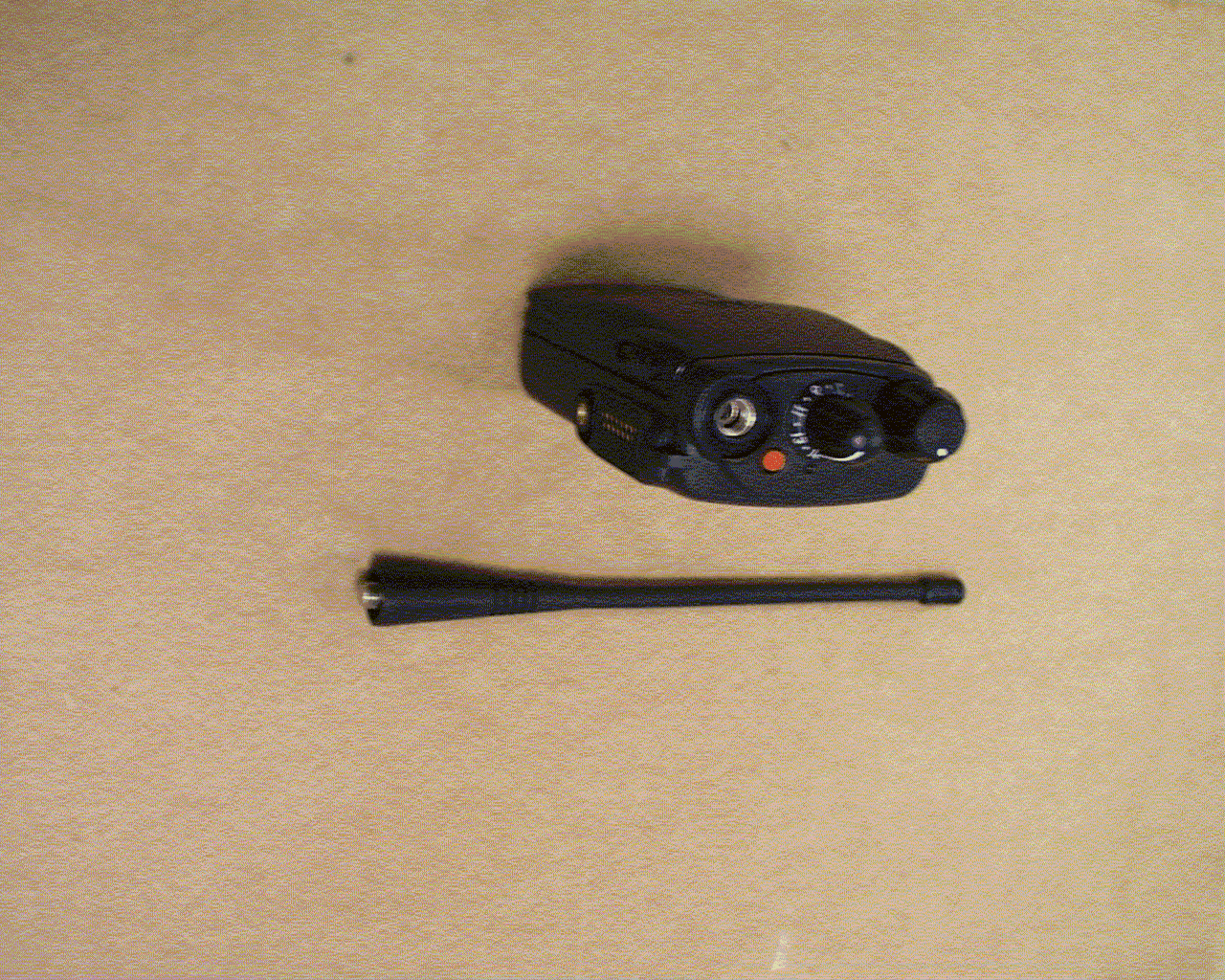
Click to zoom
Application Details
- Equipment Class
- TNF - Licensed Non-Broadcast Transmitter Held to Face
- Date of Grant
- Jun 27, 2001
- Application Purpose
- Original Equipment
- Date of Application
- Mar 26, 2001
- Equipment Note
- UHF Two-Way Radio
- Frequency Range
- 403.00000000 - 470.00000000
- Company
- Motorola Solutions, Inc.
- Country
- United States
Documents & Files
Document Text
Text extracted from the exhibit documents filed with the FCC. Open a document above to read the original.
Users Manual
1 English CONTENTS Computer Software Copyrights . . . . . . . . . . 3 Safety . . . . . . . . . . . . . . . . . . . . . . . . . . . . . 5 Safety and General Information . . . . . . . . . 5 RF Operational Characteristics . . . . . . . 5Exposure To Radio Frequency Energy . 5 Portable Radio Operation and EME Exposure . . . . . . . . . . . . . . . . . . . 6 Antenna Care . . . . . . . . . . . . . . . . . . . . . 6Two-Way Radio Operation. . . . . . . . . . . 6Body-Worn Operation . . . . . . . . . . . . . . 6Data Operation. . . . . . . . . . . . . . . . . . . . 6Approved Accessories . . . . . . . . . . . . . . 7 Electromagnetic Interference/Compatibility . . . . . . . . . . . . . . . . . . . . . . . . 7Safety and General . . . . . . . . . . . . . . . . . . . 8Operational Warnings . . . . . . . . . . . . . . . . . 8Operational Cautions . . . . . . . . . . . . . . . . . 9Intrinsically Safe Radio Information. . . . . . 10 FMRC Approved Equipment . . . . . . . . 10Repair of FMRC Approved Products . . 11 Radio Overview . . . . . . . . . . . . . . . . . . . . 15 Parts of the Radio . . . . . . . . . . . . . . . . . . . 15 On/Off/Volume Knob . . . . . . . . . . . . . . 16Channel Selector Knob . . . . . . . . . . . . 16Push-to-Talk (PTT) Button . . . . . . . . . 16Microphone . . . . . . . . . . . . . . . . . . . . . 16LED Indicator. . . . . . . . . . . . . . . . . . . . 16Programmable Buttons . . . . . . . . . . . . 16 Indicator Tones. . . . . . . . . . . . . . . . . . . . . 18Audio Indicators for ProgrammableButtons . . . . . . . . . . . . . . . . . . . . . . . . . . . 18Improved Audio Features . . . . . . . . . . . . . 19 Low Level Expansion (LLE). . . . . . . . . 19Companding . . . . . . . . . . . . . . . . . . . . 19 Getting Started . . . . . . . . . . . . . . . . . . . . 21 Battery Information . . . . . . . . . . . . . . . . . . 21 Battery Care and Tips . . . . . . . . . . . . . 21Charging your Battery . . . . . . . . . . . . . 22Battery Status . . . . . . . . . . . . . . . . . . . 22 Accessory Information . . . . . . . . . . . . . . . 24 Attaching the Battery . . . . . . . . . . . . . . 24Removing the Battery . . . . . . . . . . . . . 24Attaching the Antenna . . . . . . . . . . . . . 25Removing the Antenna . . . . . . . . . . . . 25Attaching the Side Connector Cover . . 26 Turning The Radio On or Off . . . . . . . . . . 26Adjusting the Radio’s Volume. . . . . . . . . . 27Selecting a Radio Channel . . . . . . . . . . . . 27 CONTENTS User Guide Guide de l ́usager *6881093C98* 68P81093C98-O Motorola, the stylized M logo are trademarks of Motorola, Inc.® Reg. U.S. Patent & Trademark Office. All other product orservice names are the property of their respective owners.© 2001 Motorola, Inc. All rights reserved. Printed in U.S.A.Motorola, le logo stylisé M sont des marques de commerce deMotorola, Inc. MD Marque déposée. U.S. Patent & TrademarkOffice. Tous les autres noms de produits ou servicesappartiennent à leurs propriétaires respectifs.© 2001 Motorola, Inc. Tous droits réservés. Imprimé aux États-Unis. EX500 2 English CONTENTS Sending a Call . . . . . . . . . . . . . . . . . . . . . 27Receiving a Call . . . . . . . . . . . . . . . . . . . . 27 Radio Call Information . . . . . . . . . . . . . . 29 Receiving a Selective Call . . . . . . . . . . . . 29Receiving a Call Alert™ Page . . . . . . . . . 29Emergency Alarms . . . . . . . . . . . . . . . . . . 29Talkaround . . . . . . . . . . . . . . . . . . . . . . . . 30Squelch. . . . . . . . . . . . . . . . . . . . . . . . . . . 30Power Level . . . . . . . . . . . . . . . . . . . . . . . 31 Scan . . . . . . . . . . . . . . . . . . . . . . . . . . . . . 33 Starting or Stopping a Scan Operation . . . 33Talkback . . . . . . . . . . . . . . . . . . . . . . . . . . 33Deleting a Nuisance Channel . . . . . . . . . . 33Adding a Deleted Nuisance Channel back to the Scan List . . . . . . . . . . . . . . . . . . . . . . . 34Scan Channel Discovery Alert . . . . . . . . . 34Scan List Member Priority . . . . . . . . . . . . 34 Warranty . . . . . . . . . . . . . . . . . . . . . . . . . 37 Limited Warranty . . . . . . . . . . . . . . . . . . . 37 Accessories . . . . . . . . . . . . . . . . . . . . . . 41 Carry Cases . . . . . . . . . . . . . . . . . . . . . . . 41Remote Speaker Microphones . . . . . . . . . 41Earpieces . . . . . . . . . . . . . . . . . . . . . . . . . 41 Batteries . . . . . . . . . . . . . . . . . . . . . . . . . . 41Chargers . . . . . . . . . . . . . . . . . . . . . . . . . 41Antennas . . . . . . . . . . . . . . . . . . . . . . . . . 42 3 English CONTENTS COMPUTER SOFTWARE COPYRIGHTS The Motorola products described in this manual may include copyrighted Motorola computer programs stored in semiconductor memories or other media. Laws in the United States and other countries preserve for Motorola certain exclusive rights for copyrighted computer programs, including, but not limited to, the exclusive right to copy or reproduce in any form the copyrighted computer program. Accordingly, any copyrighted Motorola computer programs contained in the Motorola products described in this manual may not be copied, reproduced, modified, reverse-engineered, or distributed in any manner without the express written permission of Motorola. Furthermore, the purchase of Motorola products shall not be deemed to grant either directly or by implication, estoppel, or otherwise, any license under the copyrights, patents or patent applications of Motorola, except for the normal non-exclusive license to use that arises by operation of law in the sale of a product. 4 English CONTENTS NOTES 5 English SAFETY SAFETY AND GENERAL INFORMATION IMPORTANT INFORMATION ON SAFE AND EFFICIENT OPERATIONREAD THIS INFORMATION BEFORE USING YOUR MOTOROLA TWO-WAY RADIO The information provided in this document supersedes the general safety information contained in user guides published prior to October 2000. For information regarding radio use in a hazardous atmosphere refer to the Factory Mutual (FM) ma…
Text truncated - open the document above for the full version.
Attestation Statements
Intertek Testing Services FCC ID: AZ489FT4844 Applicant: Motorola Inc. Page 1 of 1 EXHIBIT 2 FCC Part 90 Certification Test and Measurement Report Certification of Data Statement of Certification The technical data supplied with this application, having been taken under my supervision is hereby duly certified. The following is a statement of my qualifications: I have received a Masters of Electrical Engineering from Syracuse University, Syracuse, NY in 1989. I have more than 13 years experience in the field of EMC. Name:Grace Lin Signature:Grace Lin (signed) Date:March 27, 2001 Position:Sr. Project Engineer I hereby certify that the above application was prepared under my direction and that to the best of my knowledge and belief, the facts set forth in the application and accompanying technical data are true and correct: Name:David Schramm Signature:David J. Schramm (signed) Date:March 27, 2001 Position:EMC Team Leader
Block Diagram
Intertek Testing Services FCC ID: AZ489FT4844 Application for Motorola Inc. Page 1 of 2 Exhibit 4 FCC Part 90 Certification Test and Measurement Report 1.0MEANS FOR FREQUENCY STABILIZATION Frequency stability is maintained by a referenced oscillator/programmable temperature compensation circuit located in the frequency synthesizer IC U201. The oscillator is a Colpitts design with an amplifier in the IC. The 68.8 MHz crystal FL201. varactor and feedback capacitors are external circuitry. A control voltage applied to the varactor via the programmable compensation circuit maintains the frequency stability to within +/- 2.5ppm over temperature. Frequency tuning, also from the programmable compensation circuit, has 128 steps of resolution. 2.0MEANS FOR LIMITING MODULATION Modulation limiting is accomplished within the custom IC, U404. The limiting action itself occurs at the rails (i.e., 3.3V and ground). Using an opamp with feedback, very hard limiting is obtained. The limited modulation signal is then input through a low-pass splatter filter then to an electronic attenuator within U404 in order to adjust for variations in modulation sensitivities of the frequency synthesizer. The electronic attenuator is controlled by the radio's micro-processor, U409. To keep the deviation constant over the RF frequency range & channel bandwidth, the microcomputer adds the proper correction factor to the attenuator. 3.0MEANS FOR ATTENUATION OF HIGHER AUDIO FREQUENCIES The output of the limiter is applied to a low-pass splatter filter. The filter is a fifth-order switched capacitor filter with the roll off corner located at 3000 Hz. The output of the low- pass filter is input to the electronic attenuator before routing to the modulator. 4.0MEANS FOR ATTENUATION OF SPURIOUS EMISSIONS The final stage of the RF power amplifier circuit feeds a low-pass filter in order to attenuate harmonics of the carrier frequency as well as any spurious signals. The filter is a seven elements Elliptic design using LC lump elements. Harmonic Filter The harmonic filter consists of C104, L102, C103, L101 and C102. The design of the harmonic filter for UHF is that of a modified Zolotarev design. It has been optimized for efficiency of the power module. This type of filter has the advantage that it can give a greater attenuation in the stop-band for a given ripple level. The harmonic filter insertion loss is typically less than 1.2dB. 5.0MEANS FOR LIMITING POWER The transmitter uses the Power Control IC (PCIC), U102 to regulate the power output of the radio. The current to the final stage of the power module is supplied through R101, which provides a voltage proportional to the current drain. This voltage is then fedback to the Automatic Level Control (ALC) within the PCIC to regulate the output power of the transmitter. The PCIC has internal digital to analog converters (DACs) which provide the reference voltage of the control loop. The reference voltage level is programmable through the SPI line of the PCIC. Intertek Testing Services FCC ID: AZ489FT4844 Application for Motorola Inc. Page 2 of 2 Exhibit 4 FCC Part 90 Certification Test and Measurement Report There are resistors and integrators within the PCIC, and external capacitors (C133, C134 and C135) in controlling the transmitter rising and falling time. These are necessary in reducing the power splatter into adjacent channels. CR105 and its associated components are part of the temperature cut back circuitry. It senses the printed circuit board temperature around the transmitter circuits and output a DC voltage to the PCIC. If the DC voltage produced exceeds the set threshold in the PCIC, the transmitter output power will be reduced so as to reduce the transmitter temperature. 6.0MODULATION TECHNIQUES. The transmitter is capable of the following types of modulation: i) Voice 300Hz to 3KHz ii) Modulation of PL (Private Line) - Direct FM tone modulation of 67 Hz to 250.3 Hz at 15% of full system deviation. iii) Modulation of DPL (Digital Private Line) - Direct FM modulation at 134 BPS at 15% of full system deviation. iv) Modulation of DTMF tones at nominally 60% of full system deviation. Direct FM of PL or DPL is generated by a 6-bit D/A converter contained within U404. The frequency-determining clock signal is generated by the radio microcomputer. The modulation signal is processed through a five pole switched capacitor filter. The output of the filter is input to the electronic attenuator circuit. The microcomputer adjusts the attenuator to compensate for modulation sensitivity variations of the synthesizer & channel bandwidth ensuring 15% of full system deviation for PL and DPL. DTMF tones are generated by the audio processing IC, U404. The tones are routed and processing IC, U404. The tones are routed and processed in the same manner as the voice signals.
Cover Letter(s)
FCC ID: AZ489FT4844 Global Technology Development Group 8000 West Sunrise Boulevard, Fort Lauderdale, Florida 33322. (954) 723-5000 Date:March 27, 2001 Authorization & Evaluation Division Federal Communications Commission Laboratory 7435 Oakland Mills Road Columbia, MD 21046 Subject: Application for Certification of Transmitter with FCC ID: AZ489FT4844. Gentlemen: Motorola Inc, 8000 West Sunrise Boulevard, Fort Lauderdale, Florida, herein submits its’ application for Certification of the subject transmitter. This transmitter is primarily intended for use in a portable radio application with capabilities for clear communications with a transmit power of 1.0—4.0 Watt. The Power is variable 20% of the value listed. The subject transmitter complies with Section 90.203 of the rules in that the operator cannot directly program transmit frequencies using only the unit's normally accessible external controls. Enclosed is a complete Certification application. Contact me at (954) 723-5793 if you require any additional information. Sincerely, Mike Ramnath(signed) FCC Liaison Email: [email protected] Fax (954) 723-4794
External Photos
Intertek Testing Services FCC ID: AZ489FT4844 Applicant: Motorola Inc. Page 1 of 7 Exhibit 3 FCC Part 90 Certification Test and Measurement Report EXHIBIT 3 External Photographs 1. Back Side of Radio 2. Back Side 3D 3. Front of Radio 3D 4. Front of Radio 5. Top of Radio 6. Antenna 7. Radio without Antenna Top View Intertek Testing Services FCC ID: AZ489FT4844 Applicant: Motorola Inc. Page 2 of 7 Exhibit 3 FCC Part 90 Certification Test and Measurement Report Intertek Testing Services FCC ID: AZ489FT4844 Applicant: Motorola Inc. Page 3 of 7 Exhibit 3 FCC Part 90 Certification Test and Measurement Report Intertek Testing Services FCC ID: AZ489FT4844 Applicant: Motorola Inc. Page 4 of 7 Exhibit 3 FCC Part 90 Certification Test and Measurement Report Intertek Testing Services FCC ID: AZ489FT4844 Applicant: Motorola Inc. Page 5 of 7 Exhibit 3 FCC Part 90 Certification Test and Measurement Report Intertek Testing Services FCC ID: AZ489FT4844 Applicant: Motorola Inc. Page 6 of 7 Exhibit 3 FCC Part 90 Certification Test and Measurement Report Intertek Testing Services FCC ID: AZ489FT4844 Applicant: Motorola Inc. Page 7 of 7 Exhibit 3 FCC Part 90 Certification Test and Measurement Report
ID Label/Location Info
Intertek Testing Services FCC ID: AZ489FT4844Page 1 of 3 Exhibit 1 FCC Part 90 Certification Test and Measurement Report LIST OF EXHIBITS DESCRIPTIONEXHIBITFCC REFERENCE IIdentification label information &1A2.1033 (c) (11) General Information2.1031 & 2.1061 .1. Production Plans1B 2. Application References 3. Data Submittal Procedures ll.Certification Of Data22.907 IIIExternal Photographs32.1033 (c) (12) IVBlock Diagrams or Circuit Descriptions42.1033 (c) 1. Frequency Stabilization 2. Modulation Limiting 3. Attenuation Of Higher Audio Frequencies 4. Attenuation Of Spurious Emissions 5. Limiting Output Power 6. Modulation Techniques VSchematic Diagrams52.1033 (c) (10) VITest Report6 1. Data Index6Test report 2. RF Output Data6A2.1046 3. Modulation Characteristics2.1047 a) Audio Response6BTest Report b) Low Pass Filter Response6C c) Modulation Limiting6D 4. Occupied Bandwidth6E2.1049 5. Conducted Spurious Emissions6F2.1051 6. Radiated Spurious Emissions6G2.1053 7. Frequency Stability (Temp. & Supply Voltage)6H & 6I2.1055 8. Transient Frequency Behavior6 J90.214 VIITest Set-Up Procedures7 a) Test Equipment Used b) Method Of Measurements c) Emission Designator Information VIIIInstruction Manual82.1033 (c) (3) IXInternal Photographs92.1033 (c) (12) XParts List & Tune-Up Procedures10A & 10B2.1033 (c) (9) XIRF Exposure Information112.1093 (c) and (d) XIIOperation Description122.1033(c) 10 a) Technical Characteristics2.1033 (c) b) Application XIIICover Letter132.1033(c) 10 Intertek Testing Services FCC ID: AZ489FT4844Page 2 of 3 Exhibit 1 FCC Part 90 Certification Test and Measurement Report Applicant: Motorola Inc. FCC ID: AZ489FT4844 Location:See attached photograph Type:The label is a paper polyester firm laminate with a pressure sensitive adhesive backing. The adhesive is a permanent type acrylic with a minimum peel strength of 40 inches/oz. Markings:Label attached below Exhibit 1a: FCC ID Label Format Intertek Testing Services FCC ID: AZ489FT4844Page 3 of 3 Exhibit 1 FCC Part 90 Certification Test and Measurement Report General Information IProduction Plans – Pursuant 2.1033 Quantity production is planned IIApplication References – Pursuant 2.1061 Application is made to the following Motorola “Application References” 1. Portable Products and their application 2. Portable Products Transmitter Modulation Methods 3. Motorola Plantation Antenna Range IIIData submittal procedure: Data is supplied in accordance with Part 2, Sub-part J of the Commissions’ rules.
Internal Photos
Intertek Testing Services FCC ID: AZ489FT4844 Applicant: Motorola Inc. Page 1 of 7 Exhibit 9 FCC Part 90 Certification Test and Measurement Report EXHIBIT 9 INTERNAL PHOTOGRAPHS 1. Side 1 RF Board connected to Top Open 2. Inside of Front Cover 3. RF Board Side 2 4. Back Cover Inside 5. Controller connected to RF Board via Flex 6. RF Board Side 1 7. Controller Side 2 Intertek Testing Services FCC ID: AZ489FT4844 Applicant: Motorola Inc. Page 2 of 7 Exhibit 9 FCC Part 90 Certification Test and Measurement Report Intertek Testing Services FCC ID: AZ489FT4844 Applicant: Motorola Inc. Page 3 of 7 Exhibit 9 FCC Part 90 Certification Test and Measurement Report Intertek Testing Services FCC ID: AZ489FT4844 Applicant: Motorola Inc. Page 4 of 7 Exhibit 9 FCC Part 90 Certification Test and Measurement Report Intertek Testing Services FCC ID: AZ489FT4844 Applicant: Motorola Inc. Page 5 of 7 Exhibit 9 FCC Part 90 Certification Test and Measurement Report Intertek Testing Services FCC ID: AZ489FT4844 Applicant: Motorola Inc. Page 6 of 7 Exhibit 9 FCC Part 90 Certification Test and Measurement Report Intertek Testing Services FCC ID: AZ489FT4844 Applicant: Motorola Inc. Page 7 of 7 Exhibit 9 FCC Part 90 Certification Test and Measurement Report
Operational Description
Intertek Testing Services FCC ID: AZ489FT4844Page 1 of 1 Exhibit 12 FCC Part 90 Certification Test and Measurement Report OPERATIONAL DESCRIPTION 1.Transmitter Technical Characteristics -- Pursuant 2.983 (d) a. RF Power Out: 1W to 4.0 Watt Variable Power b. Transmit Frequency Range:403-470 MHz c. Receive Frequency Range:403-470 MHz d. Frequency Stability:2.5 PPM e. Emissions11K0F3E, 16K0F3E f. DC Voltage and Current into7.5 VDC the final RF amplifier stage/stages1.18 Amps 2.Transmitter Application This transmitter is primarily intended for use in a portable environment. The following features, options, and accessories characterize the Transmitter: a. Power Supply Available: i. LiIon Rechargeable Low Capacity Battery ii. LiIon Rechargeable High Capacity Battery iii NiMH Rechargeable Battery b. Antenna Available: i. Helical Antenna ii. Whip antenna c. Squelch Type Available: i. Carrier Squelch ii. Tone “Private Line” iii. Digital “Private Line” iv. DTMF v. MDC vi. Quick Call II d. Microphone - Control: I. Handset/Palm Microphone e. Maximum Transmit Channel Capability: i. 16 Channel f. Housing: i. The transmitter will be housed in the housing shown in the accompanying photographs g. Other Options: i. Time out Timer
Parts List/Tune Up Info
Intertek Testing Services FCC ID: AZ489FT3801Page 1 of 3 Exhibit 10a FCC Part 90 Certification Test and Measurement Report EXHIBIT 10A Transmit Power Tuning Power tuning is performed using Motorala Professional Radio Tuning Software available to Motorola Technical Field Representatives. There are 2 variations of Transmit Power Tuning; they are High Power and Low Power Tuning. Note : When checking the RF power output of the radio with a test set, always use a pad of at least 30dB attached to the radio end of the RF cable. This will avoid an RF mismatch and ensure a stable RF reading that will not change with varying lengths of connecting cable. Transmit High Power level for Professional portable radios RF Band (MHz)High Power (W) VHF (136-174)5.2 - 5.7 UHF Band 1 (403-470)4.2 - 4.6 UHF Band 2 (450-527)4.2 - 4.5 To perform Transmit High Power Tuning, do the following:- 1.Under the Tx Align menu, select Transmit Power, then select High. 2.Press PTT Toggle. This will key the radio up at F1. 3.Adjust the high power level to be as defined by country power level specifications by moving the slider/spin control or keying in values in the edit control (press ENTER to confirm your selection after typing in the softpot value). 4.Press PTT Toggle to dekey the radio, go to the next frequency point by selecting the slider, typing in the edit control box (press ENTER to confirm selection after typing in the softpot value) or toggling the softpot value using the spin control. 5.Press PTT Toggle again to key up the radio at the selected frequency point. 6.Repeat steps 3-5 for (F2-F7). 7.Press Program to store the softpot values into the radio’s codeplug. 8.Exit the Transmit High Power function. Intertek Testing Services FCC ID: AZ489FT3801Page 2 of 3 Exhibit 10a FCC Part 90 Certification Test and Measurement Report 9.If the radio uses only high power channels, proceed to adjust modulation. If low power channels are used, perform Transmit Low Power Tuning as defined below. Transmit Low Power level for Professional portable radios RF Band (MHz)Low Power (W) VHF (136-174)1.1 - 1.3 UHF Band 1 (403-470)1.1 - 1.45 UHF Band 2 (450-527)1.1 - 1.45 To perform Transmit Low Power Tuning, do the following:- 1.Under the Tx Align menu, select Transmit Power, then select Low. 2.Press PTT Toggle. This will key the radio up at F1. 3.Adjust the power level to be as defined by country power level specifications by moving the slider/spin control or keying in values in the edit control (press ENTER to confirm your selection after typing in the softpot value). 4.Press PTT Toggle to dekey the radio, go to the next frequency point by selecting the slider, typing in the edit control box (press ENTER to confirm your selection) or toggling the softpot value using the spin control. 5.Press PTT Toggle again to key up the radio at the selected frequency point. 6.Repeat steps 3-5 for (F2-F7). 7.Press Program to store the softpot values into the radio’s codeplug. 8.Exit the Transmit Low Power function PA Bias Tuning IMPORTANT: Tuning must be performed for both High and Low power for UHF and VHF radios. 1. Ensure that the radio’s antenna output is terminated in a 50 Ohm load. This is to prevent self destruction of the PA. 2. Under Tx Align, select PA Bias, select High Power. 3. Measure/read the dc current drawn by the radio (specifications will vary from radio to radio). Call this X. This value should typically range from 70-100mA or 0.07-0.1A. 4. Press Toggle Voltage to enable the PA control voltage edit box/spin control. Intertek Testing Services FCC ID: AZ489FT3801Page 3 of 3 Exhibit 10a FCC Part 90 Certification Test and Measurement Report 5. Increase the Voltage softpot value and measure/read the current from the meter. Call the new value Y. 6. Increase Y until Y - X is within the range given for PA current in table below. 7. Press Toggle Voltage again to disable the PA control voltage edit box/spin control. 8. Press Toggle Bias 1 in order to enable the PA Bias softpot. 9. Increase the softpot value to obtain Z until Z - Y is within the range for Bias Current as indicated in the table below.. 10. Press Toggle Bias 1 again to disable the PA Bias softpot. 11. Program the Bias softpot into the radio’s codeplug by pressing Program. 12. Exit the PA Bias High Power function. 13. Under Tx Align, select PA Bias, Low Power. 14. Repeat steps 3-11. 15. Exit the PA Bias Low Power function. VHFPA CurrentBias Current 136-17490mA – 110mA90mA – 110mA
Parts List/Tune Up Info
UHF Band 1, Circuit Board/Schematic Diagrams and Parts List 4-39 UHF Band 1 Radio Parts List Circuit Ref Motorola Part No. Description B501 0986237A02 Battery Contact Module C101 2113740F51 100 C102 2113740F22 6.2 C103 2113740F27 10 C104 2113740F22 6.2 C105 2113743N50 100PF C106 2113740F19 4.7PF C107 2113740F15 3.3 C108 2113743N50 100PF C109 2113740F51 100 C110 2113743N50 100PF C111 2113740F30 13 C112 2180605Z32 47PF C113 2180605Z16 10PF C114 2113743N50 100PF C115 2113743N30 15.0PF C116 2113743N38 33.0PF C117 2113743N37 30.0PF C118 2113743N50 100PF C119 2113743N50 100PF C120 2113743N26 10.0PF C121 2113743N50 100PF C122 2113743N50 100PF C123 2311049A18 10UF C125 2113743N50 100PF C126 2113743M24 0.1UF,+80%/-20% C127 2113743L17 1000PF,10% C128 2113743M08 22000PF C129 2113743N23 7.5PF C130 2113743N50 100PF C131 2113743M08 22000PF C132 2113743N50 100PF C133 2113743L17 1000PF,10% C134 2113743L29 3300PF C135 2113743M08 22000PF C138 2113743N50 100PF C150 2113743M08 22000PF C151 2113743N50 100PF C152 2113743M08 22000PF C160 2113743N50 100PF C161 2113743M24 0.1UF,+80%/-20% C165 2113743N50 100PF C166 2113743N50 100PF C169 2113743N20 5.6PF C170 2113743N50 100PF C171 2113743N50 100PF C172 2113743E20 10UF C173 2113743M08 22000PF C174 2113743N50 100PF C175 2113740L25 20PF C201 2113743N50 100PF C202 2113743L17 1000PF,10% C203 2311049A56 4.7UF C204 2104993J02 2.2UF C206 2113740F63 330 C207 2113743N40 39.0PF C208 2113743N08 1.6PF C210 2113743N50 100PF C211 2113743N50 100PF C212 2113743N50 100PF C213 2113743N50 100PF C214 2113743N50 100PF C217 2104993J02 2.2UF C218 2113743M24 0.1UF,+80%/-20% C219 2113743K16 0.220UF,+80%/-20% C220 2113743N50 100PF C223 2113743M24 0.1UF,+80%/-20% C224 2113743M24 0.1UF,+80%/-20% C228 2311049J11 4.7UF C229 2113743L17 1000PF,10% C230 2113743N50 100PF C231 2113743M24 0.1UF,+80%/-20% C232 2113743E12 0.047UF C233 2311049A01 0.1UF C234 2311049A05 0.47UF C235 2104993J02 2.2UF C238 2113741F17 470 C241 2113743N50 100PF C242 2113743N23 7.5PF C243 2113743N23 7.5PF C244 2113740F10 2 C245 2113743N11 2.4PF C246 2113743N50 100PF C247 2113743N50 100PF C248 2113743M24 0.1UF,+80%/-20% C250 2113743N23 7.5PF C251 2113743N50 100PF C252 2113743N26 10.0PF C253 2113740F09 1.8 C254 2113743N15 3.6PF C255 2113743N50 100PF C257 2113743N50 100PF C258 2113743L41 1000PF C259 2113743L41 1000PF C260 2113743N50 100PF C263 2113743N02 0.75PF C264 2113743N50 100PF C273 2113743M24 0.1UF,+80%/-20% C276 2104993J02 2.2UF C277 2113743N50 100PF Circuit Ref Motorola Part No. Description C278 2311049A09 2.2UF C279 2104993J02 2.2UF C281 2113743N50 100PF C285 2113743N50 100PF C286 2113743M24 0.1UF,+80%/-20% C289 2113743N50 100PF C291 2311049A69 10.0UF C292 2113743M24 0.1UF,+80%/-20% C293 2113743A27 0.470UF C294 2113743N50 100PF C295 2113743N50 100PF C296 2113743M24 0.1UF,+80%/-20% C297 2113743L41 1000PF C298 2113743M24 0.1UF,+80%/-20% C301 2113743N15 3.6PF C302 2113743N26 10.0PF C303 2113740L08 3.9PF C304 2113743N26 10.0PF C305 2113743N33 20.0PF C307 2113743M24 0.1UF,+80%/-20% C308 2113743N50 100PF C309 2113743N50 100PF C310 2113743M24 0.1UF,+80%/-20% C312 2113743N25 9.1PF C313 2113743N26 10.0PF C314 2113743M24 0.1UF,+80%/-20% C315 2113743N50 100PF C316 2113740L08 1200PF C317 2113743N25 9.1PF C318 2113743N23 7.5PF C319 2113743N69 1.8PF C320 2113743N23 7.5PF C321 2113743N50 100PF C322 2113743N48 82.0PF C323 2113743N54 150PF C324 2113743N33 20.0PF C325 2113743L41 1000PF C326 2113743L41 1000PF C327 2113743N50 100PF C328 2113743M24 0.1UF,+80%/-20% C329 2113743M24 0.1UF,+80%/-20% C330 2113743N26 10.0PF C331 2113743N50 100PF C334 2113743M08 22000PF C336 2113743M24 0.1UF,+80%/-20% C337 2113743N50 100PF C338 2113743N30 15.0PF C339 2180478Z20 1.0UF C340 2180478Z20 1.0UF C341 2180478Z20 1.0UF C342 2180478Z20 1.0UF Circuit Ref Motorola Part No. Description C343 2113743A23 0.220UF,10% C344 2113743M24 0.1UF,+80%/-20% C345 2113743M24 0.1UF,+80%/-20% C346 2113743M24 0.1UF,+80%/-20% C347 2113743M24 0.1UF,+80%/-20% C348 2113743M24 0.1UF,+80%/-20% C349 2113743E07 0.022UF,10% C350 2113743L05 330PF,10% C351 2113743N33 20.0PF C352 2113743N28 12.0PF C353 2113743N41 43.0PF C354 2113743N42 47.0PF C355 2113743A24 0.330UF C356 2113743M08 22000PF C357 2113743A23 0.220UF,10% C358 2113741A23 1200PF C359 2109720D14 0.1UF C360 2113743E07 0.022UF,10% C361 2113741F49 10NF C362 2113743M08 22000PF C363 2311049A40 2.2UF C364 2113743L41 1000PF C370 2113743N50 100PF C374 2113743N50 100PF C375 2113743N50 100PF C380 2113743L41 1000PF C381 2113743N21 6.2PF C382 2311049A59 10UF C383 2113743N50 100PF C384 2113743N44 56.0PF C385 2113743N44 56.0PF C386 2113743N50 100PF C390 2113743N50 100PF C395 2113743N50 100PF C397 2311049A05 0.47UF C400 2113743L41 0.01uF,10% C401 2113743M24 100000 PF +80-20% C402 2113743M24 100000 PF +80-20% C403 2113928D08 10.0UF C408 2113743N50 100 PF 5% C409 2113743M24 100000 PF +80-20% C410 2113928N01 0.1UF 10% C411 2113743M24 100000 PF +80-20% C414 2113743M24 100000 PF +80-20% C415 2185895Z01 0.1uF C416 2113928N01 0.1UF 10% C420 2113743L41 0.01uF,10% C421 2113928N01 0.1UF 10% C422 2113743M24 100000 PF +80-20% C423 2113743N50 100PF 5% C424 2311049A59 10UF 10% Circuit Ref Motorola Part No. Description 4-40 UHF Band 1, Circuit Board/Schematic Diagrams and Parts List C425 2113743M24 100000 PF +80-20% C426 2113743N50 100PF 5% C427 2113743N50 100PF 5% C428 2113743M24 100000 PF +80-20% C429 2113743M24 100000 PF +80-20% C430 2113928N01 0.1UF 10% C431 2113743N50 100PF 5% C433 2113743L41 0.01uF,10% C435 2113743M24 100000 PF +80-20% C440 2113743G26 4.7uF C441 2113743N50 100PF 5% C442 2113743E20 10uF C443 2113928N01 0.1UF 10% C444 2113743N50 100PF 5% C445 2113743N50 100PF 5% C447 2113928N01 0.1UF 10% C448 2113928N01 0.1UF 10% C449 2113743N50 100PF 5% C451 2113743M08 22000PF +80-20% C452 2113743B29 1.00 μf C453 2113743N50 100PF 5% C456 2113743N50 100PF 5% C471 2113743N50 100PF 5% C472 2113743N50 100PF 5% C473 2113743N50 100PF 5% C475 2113743H14 10.0uF C476 2113928D08 10.0UF C479 2113928N01 0.1UF 10% C480 2113928D08 10.0UF C481 2113928N01 0.1UF 10% C490 2…
Text truncated - open the document above for the full version.
RF Exposure Info
Intertek Testing Services FCC ID: AZ489FT4844 Application for Motorola Inc. Page 1 of 1 EXHIBIT 11 FCC Part 90 Certification Test and Measurement Report RF Exposure Information In accordance with 47 CFR 2.1093 (c), this transmitter is categorically exempted from routine environmental evaluation for RF Exposure prior to equipment authorization or use.
RF Exposure Info
Form SAR-Rpt-B Page 1 of 1 Certificate Number 1449-02 ELECTROMAGNETIC EXPOSURE (EM…
Text truncated - open the document above for the full version.
Contact Information
Applicant
Deanna Zakharia(Regulatory Compliance Manager)
Technical Contact
Intertek Testing ServicesDavid J Schramm
[email protected](678) 775-2400
1950 Evergreen Blvd · Duluth, Georgia · United States
Non-Technical Contact
Intertek Testing ServicesDavid J Schramm
[email protected](678) 775-2400
Test Firm
Intertek Testing ServicesDavid Schramm
Technical Specifications
| # | Rule Parts | Frequency Range | Power Output | Emission | Tolerance |
|---|---|---|---|---|---|
| 2 | 9 | 403 MHz - 470 MHz | 4.4 W | 16K0F3E | 2.5 ppm |
Other Applications from Motorola Solutions, Inc.

AZ489FT4980
Sep 08, 2026Portable two way radio
Equipment Class
TNF - Licensed Non-Broadcast Transmitter Held to FaceAZ489FT4981
Aug 14, 2026Handheld Portable - TANAPA BPR 45 400-470 MHZ 4W NKP
Equipment Class
TNF - Licensed Non-Broadcast Transmitter Held to Face
AZ489FT7187
Jul 13, 2026Portable 2-Way Radio with Bluetooth, Bluetooth LE, WIFI 2.4GHz, WIFI 5GHz, LTE
Equipment Class
DSS - Part 15 Spread Spectrum TransmitterAZ499FT6031
May 11, 2026Operation Critical Wireless Earpiece PTT
Equipment Class
DSS - Part 15 Spread Spectrum Transmitter
AZ499FT5879
Dec 19, 20252-way Portable Radio with BT, BTLE, WIFI, NFC and LTE
Equipment Class
DSS - Part 15 Spread Spectrum Transmitter