AZ489FT4850T6400
Motorola Solutions, Inc.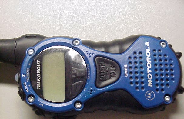
Click to zoom
Application Details
- Equipment Class
- FRF - Part 95 Family Radio Face Held Transmitter
- Date of Grant
- Oct 09, 2001
- Application Purpose
- Original Equipment
- Date of Application
- Aug 02, 2001
- Equipment Note
- T6400
- Frequency Range
- 467.56250000 - 467.71250000
- Company
- Motorola Solutions, Inc.
- Country
- United States
Documents & Files
Document Text
Text extracted from the exhibit documents filed with the FCC. Open a document above to read the original.
Users Manual
6864110R05-O @6864110R05@ Model T6400 2 Contents PRELIMINARY Safety General Information . . . iFCC License . . . . . . . . . . . . . . 1Getting Started . . . . . . . . . . . . 2Installing Batteries . . . . . . . . . . . 3CommPort™ Charging Dock . . 6Basic Operation of Radio . . . . 9Belt Clip . . . . . . . . . . . . . . . . 10Backlight . . . . . . . . . . . . . . . . . 14Talking . . . . . . . . . . . . . . . . . . 15Before You Can Talk . . . . . . . . 15To Talk . . . . . . . . . . . . . . . . . . 17Call Tone and Call Display . . . 19Alerts . . . . . . . . . . . . . . . . . . . 20VibraCall® Alert . . . . . . . . . . . 20Keeping Time . . . . . . . . . . . . . 21Setting the Time . . . . . . . . . . . 21 Setting the Alarm . . . . . . . . . . . 22Stopwatch . . . . . . . . . . . . . . . . 23 Hands-Free Use (VOX) . . . . . 24 Privacy . . . . . . . . . . . . . . . . . . 25Eavesdrop Reducer . . . . . . . . . 25QuieT6000 ™ . . . . . . . . . . . . . . 26 Advanced Two-Way . . . . . . . 27Lock . . . . . . . . . . . . . . . . . . . . . 26LockPlus . . . . . . . . . . . . . . . . . 26Channel Scanning . . . . . . . . . . 27Talk Confirmation Tone . . . . . . 28Button Beeps . . . . . . . . . . . . . . 28Automatic Power Off . . . . . . . . 29Monitor . . . . . . . . . . . . . . . . . . 29Reset . . . . . . . . . . . . . . . . . . . . 30Setting the Battery Type . . . . 30Use and Care . . . . . . . . . . . . . 31Frequency and Code Charts 33Troubleshooting . . . . . . . . . . 36Motorola Limited Warranty . . 39 SAFETY AND GENERAL INFORMATION i PRELIMINARY SAFETY AND GENERAL INFORMATIONIMPORTANT INFORMATION ON SAFE AND EFFICIENT OPERATIONREAD THIS INFORMATION BEFORE USING YOUR RADIO. The information provided in this document supersedes the general safety information contained in user guides published prior to July 2000. For information regarding radio use in a hazardous atmosphere please refer to the Factory Mutual (FM) Approval Manual Supplement or Instruction Card, which is included with radio models that offer this capability.RF Operational CharacteristicsYour radio contains a transmitter and a receiver. When it is ON, it receives and transmits radio frequency(RF) energy. The radio operates in the frequency range of 462 MHz to 467 MHz and employs analogue modulation techniques.The output power level typically may vary over a range from 0.5 watts to 1.0 watt.Exposure To Radio Frequency EnergyYour Motorola radio is designed to comply with the following national and international standards and guidelines regarding exposure of human beings to radio frequency electromagnetic energy: • United States Federal Communications Commission, Code of Federal Regulations; 47 CFR part 2 sub-part J • American National Standards Institute (ANSI) / Institute of Electrical and Electronic Engineers (IEEE) C95. 1-1992 • Institute of Electrical and Electronic Engineers (IEEE) C95.1-1999 Edition • National Council on Radiation Protection and Measurements (NCRP) of the United States, Report 86, 1986 SAFETY AND GENERAL INFORMATION ii PRELIMINARY • International Commission on Non-Ionizing Radiation Protection (ICNIRP) 1998 • Ministry of Health (Canada) Safety Code 6. Limits of Human Exposure to Radiofrequency Electromagnetic Fields in the Frequency Range from 3 kHz to 300 GHz, 1999 • Australian Communications Authority Radiocommunications (Electromagnetic Radiation - Human Exposure) Standard 1999 (applicable to wireless phones only) To assure optimal radio performance and make sure human exposure to radio frequency electromagnetic energy is within the guidelines set forth in the above standards, always adhere to the following procedures: PORTABLE RADIO OPERATION AND EME EXPOSUREAntenna CareUse only the supplied or an approved replacement antenna. Unauthorized antennas, modifications, or attachments could damage the radio and may violate FCC regulations.DO NOT hold the antenna when the radio is “IN USE.” Holding the antenna affects call quality and may cause the radio to operate at a higher power level than needed. Two-way Radio OperationWhen using your radio as a traditional two-way radio, hold the radio in a vertical position with the microphone one to two inches (2.5 to 5 cm) away from the lips. SAFETY AND GENERAL INFORMATION iii PRELIMINARY Body-worn OperationTo maintain compliance with FCC/Health Canada RF exposure guidelines, if you wear a radio on your body when transmitting, always place the radio in a Motorola supplied or approved clip, holder, holster, case, or body harness for this product. Use of non-Motorola-approved accessories may exceed FCC/Health Canada RF exposure guidelines. If you do not use a body-worn accessory, and are not using the radio held in the normal use position at the ear, ensure the radio and its antenna are at least one inch (2.5 cm) from your body when transmitting . Data operationWhen using any data feature of the radio, with or without an accessory cable, position the radio and its antenna at least one inch (2.5 cm) from the body.Approved AccessoriesFor a list of approved Motorola accessories visit our website at www.mot.com.ELECTROMAGNETIC INTERFERENCE/COMPATIBILITY Note: Nearly every electronic device is susceptible to electromagnetic interference (EMI) if inadequately shielded, designed or otherwise configured for electromagnetic compatibility. • FACILITIES To avoid electromagnetic interference and/or compatibility conflicts, turn off your radio in any facility where posted notices instruct you to do so. Hospitals or health care facilities may be using equipment that is sensitive to external RF energy. SAFETY AND GENERAL INFORMATION iv PRELIMINARY • AIRCRAFT When instructed to do so, turn off your radio when on board an aircraft. Any use of a radio must be in accordance with applicable regulations per airline crew instructions. • MEDICAL DEVICES PacemakersThe Advanced Medical Technology Association recommends that a minimum separation of 6 inches (15 centimeters) be maintained between a handheld wire…
Text truncated - open the document above for the full version.
Users Manual
The insert will be 3” x 5”, printed on bright colored paper stock (e.g. Yellow, Orange etc), with black type. IMPORTANT FCC Licensing Information This Motorola radio operates on General Mobile Radio Service (GMRS) frequencies and is subject to the Rules of the Federal Communications Commission (FCC). The FCC requires the issuance of a radio license before operating on GMRS frequencies. Instructions on applying for the license are included in the User’s Guide. For more GMRS information, see http://www.fcc.gov/wtb/prs/genmbl.html Violations of FCC rules and unlicensed operation on GMRS frequencies may subject the radio operator to serious penalties as provided in Sections 501 and 502 of the Communications Act, as amended. When operating on Channels1–7or15–22,this radio is using GMRS frequencies. In addition to having a license before using these channels, every GMRS user must cooperate in sharing channels with other GMRS users by monitoring the channel before initiating transmissions, waiting until communications in progress are completed before initiating transmissions except in an emergency, engaging in only permissible communications, limiting transmissions to the minimum practical transmission time, and using the call sign issued by the FCC for station identification.
Cover Letter(s)
FCC ID: AZ489FT4850 CPD, Motorola Inc., 8000 W. Sunrise Blvd., Plantation, FL 33322 Page: 13-1 2 nd August 2001 Authorization & Evaluation Division Federal Communications Commission Laboratory 7435 Oakland Mills Road Columbia, MD 21046 Gentlemen; Motorola Inc., 8000 West Sunrise Boulevard, Fort Lauderdale, Florida 33322, herein submits its application for Certification of the transmitter with FCC ID: AZ489FT4850. This transceiver operates on both the General Mobile Service (GMRS) and Family Radio Service (FRS) frequencies. The radio will provide 1.0 Watt conducted when transmitting on GMRS frequencies (462.5500-462.7250 MHz) and no more than 0.5 Watt ERP on FRS specific frequencies (467.5625- 467.7125 MHz). See the Frequency Table below for this Radio. Channel 1: 462.5625 MHz (GMRS 1W) Channel 2: 462.5875 MHz (GMRS 1W) Channel 3: 462.6125 MHz (GMRS 1W) Channel 4: 462.6375 MHz (GMRS 1W) Channel 5: 462.6625 MHz (GMRS 1W) Channel 6: 462.6875 MHz (GMRS 1W) Channel 7: 462.7125 MHz (GMRS 1W) *Channel 8: 476.5625 MHz (FRS 0.5W) *Channel 9: 467.5875 MHz (FRS 0.5W) *Channel 10: 467.6125 MHz (FRS 0.5W) *Channel 11: 467.6375 MHz (FRS 0.5W) *Channel 12: 467.6625 MHz (FRS 0.5W) *Channel 13: 467.6875 MHz (FRS 0.5W) *Channel 14: 467.7125 MHz (FRS 0.5W) Channel 15: 462.5500 MHz (GMRS 1W) Channel 16: 462.5750 MHz (GMRS 1W) Channel 17: 462.6000 MHz (GMRS1W) Channel 18: 462.6250 MHz (GMRS 1W) Channel 19: 462.6500 MHz (GMRS 1W) Channel 20: 462.6750 MHz (GMRS 1W) Channel 21: 462.7000 MHz (GMRS 1W) Channel 22: 462.7250 MHz (GMRS 1W) FCC ID: AZ489FT4850 CPD, Motorola Inc., 8000 W. Sunrise Blvd., Plantation, FL 33322 Page: 13-2 * FRS specific frequencies only. The T6400 radio will not be user programmable. The RF power on the T6400 radio will be set from the factory and cannot be adjusted by the user. The radio will be tuned, at the factory, to 0.5 Watt and the associated value stored in the radio codeplug. This value will be the default power setting for the radio and used on the FRS specific frequencies on channels 8 to 14. For the GMRS frequencies, the power is adjusted to 1.0 Watt by software. Once a GMRS channel is selected, the software sets the power control voltage on the RF PA for maximum power. The RF PA is limited to 1.0 Watt maximum by design. The factory measures the RF power on the GMRS band to assure 1.0 Watt is obtained. It is required that the user obtains a FCC license to operate on the GMRS frequencies. This is specified in the users manual along with information on where to obtain the necessary application forms. Enclosed is a complete Certification Application comprised of 12 Exhibits. Contact me at (954) 723-5793 if you require any additional information. Regards, /s/ Mike Ramnath FCC Liaison Email: [email protected]
Cover Letter(s)
FCC ID: AZ489FT4850 CPD, Motorola Inc., 8000 W. Sunrise Blvd., Plantation, FL 33322 Page: 13-1 REQUEST FOR CONFIDENTIALITY 2 nd August 2001 Authorization & Evaluation Division Federal Communications Commission Laboratory 7435 Oakland Mills Road Columbia, MD 21046 Subject: Application for Type Acceptance of Transmitter with FCC ID: AZ489FT4850. Gentlemen: Motorola is requesting that Exhibit 4 (Circuit Description), Exhibit 5 (Schematic Diagrams, (Exhibit 9 (Internal Photographs) and Exhibit 10 (Semiconductor/Active Device List) not be made routinely available for public inspection. Motorola has a number of Patent applications pending. Please mark Exhibit 4, 5, 9 and 10 as Confidential. Contact me at (954) 723-5793 if you require any additional information. Regards, Mike Ramnath FCC Liaison Email: [email protected]
Cover Letter(s)
FCC ID: AZ489FT4850 9 th October 2001 Mr. Andy Leimer Authorization & Evaluation Division Federal Communications Commission Laboratory 7435 Oakland Mills Road Columbia, MD 21046 Re: Form 731 Confirmation Number: EA101909 with FCC ID: AZ489FT4850. Dear Mr. Leimer; Motorola Inc., 8000 West Sunrise Boulevard, Fort Lauderdale, Florida 33322, herein submits its response to the 4 th October 2001request for information in Correspondence Number 20827. Q1. Confidentiality is requested for the Internal Photos. This cannot be done since this is public information once the device is marketed. Please submit a signed letter waiving the original request for confidentiality of the internal photos. R1. We are submitting an amended Exhibit 13a waiving the original Request for Confidentiality of Exhibit 9, Internal Photos. Q2. The schematics are unreadable. Please resubmit them in a clear readable format. R2. Reformatted Schematics are submitted under Exhibit 5. Q3. Please submit an exhibit showing an informational insert inside the box (product package) that clearly informs the consumer (buyer/owner) when the radio is transmitting on GMRS frequencies, that operation on GMRS frequencies requires an FCC license and such operation is subject to additional rules specified in 47 C.F.R. Part 95. R3. The informational sheet is submitted as Exhibit 8a, supplemental information for the Users Manual. Q4. The power output ERP is calculated from the conducted power and average measured antenna gain. The measured antenna gain is based on an infinite ground plane. This is not equivalent to the actual antenna gain when the antenna is mounted on the device. The device itself will provide a totally different ground plane. Upload an exhibit with the measured ERP for both FRS and GMRS modes using the substitution method. Note that the GMRS ERP cannot exceed 600 mW as explained in the FYI below). R4. ERP data for both FRS and GMRS modes are submitted as Exhibit 6a using the Substitution Method. A fully assembled radio with the antenna attached was used for measuring ERP for the FRS and GMRS modes. Q5. The test report shows emissions masks, transient response and radiated emissions limits for a Part 90 device. It is my understanding that this device is a combined FRS (Part 95B) and GMRS (Part 95A) device. Please verify this. R5. This is a Part 95A and Part 95B device. Please ignore all Part 90 related information. FCC ID: AZ489FT4850 Q6. The Audio Response plot shows curves for "data", "high spec", and "low spec." Please define these terms. R6. An updated Exhibit 6B of the Audio Response plot is submitted with the terms “data”, "high spec", and "low spec." defined. Data is the Audio Frequency response, High Spec. is the Upper Spec. Limit as defined in TIA/EIA SP-2218 Section 5.2.6.2 and the Low Spec. is the Lower Spec. Limit as defined in TIA/EIA SP-2218 Section 5.2.6.2. Q7. The Operation Description does not explain how the power is controlled between the FRS and GMRS modes. Explain how this is done. R7. This transceiver operates on both the General Mobile Service (GMRS) and Family Radio Service (FRS) frequencies. The radio will provide 1.0 Watt conducted when transmitting on GMRS frequencies (462.5500-462.7250 MHz) and no more than 0.5 Watt ERP on FRS specific frequencies (467.5625-467.7125 MHz). See the Frequency Table below for this Radio. Channel 1: 462.5625 MHz (GMRS 1W) Channel 2: 462.5875 MHz (GMRS 1W) Channel 3: 462.6125 MHz (GMRS 1W) Channel 4: 462.6375 MHz (GMRS 1W) Channel 5: 462.6625 MHz (GMRS 1W) Channel 6: 462.6875 MHz (GMRS 1W) Channel 7: 462.7125 MHz (GMRS 1W) *Channel 8: 476.5625 MHz (FRS 0.5W) *Channel 9: 467.5875 MHz (FRS 0.5W) *Channel 10: 467.6125 MHz (FRS 0.5W) *Channel 11: 467.6375 MHz (FRS 0.5W) *Channel 12: 467.6625 MHz (FRS 0.5W) *Channel 13: 467.6875 MHz (FRS 0.5W) *Channel 14: 467.7125 MHz (FRS 0.5W) Channel 15: 462.5500 MHz (GMRS 1W) Channel 16: 462.5750 MHz (GMRS 1W) Channel 17: 462.6000 MHz (GMRS1W) Channel 18: 462.6250 MHz (GMRS 1W) Channel 19: 462.6500 MHz (GMRS 1W) Channel 20: 462.6750 MHz (GMRS 1W) Channel 21: 462.7000 MHz (GMRS 1W) Channel 22: 462.7250 MHz (GMRS 1W) * FRS specific frequencies only. The T6400 radio will not be user programmable. The RF power output level of the T6400 radio will be electronically tuned in the factory and cannot be adjusted by any other means. The associated tune value is stored in a radio internal memory location (code plug). The radio will be tuned as follows: For FRS operation, the automated test system first measures the conducted RF output power on FRS channel 11 (Freq = 467.6375 MHz) and at 4.5VDC +/- .005VDC. If the power is within the tune window of 500 to 550mW a default code plug value is used. If the power measured is higher than 550mW the test system reduces the default codeplug value until the power is within the tune target. If the power measured is lower than the 500mW, FCC ID: AZ489FT4850 the test system increases the default code plug value until the power is within the tune target. This new code plug value will now become the default power setting for this particular radio and used on the FRS specific frequencies on channels 8 to 14. Modification to the radio codeplug is not possible without access to Motorola proprietary information of the codeplug bitmap, programming software, and hardware, which are for Motorola internal use only at the manufacturing facilities. For the GMRS frequencies, the conducted RF output power is controlled to 1.0 Watt by Motorola proprietary software developed specifically for this family of radios. The automated test system selects a GMRS channel and the radio software sets the power control voltage on the RF power amplifier (PA) to it’s maximum setting. The RF PA is limited to 1.0-Watt maximum conducted power by the performance capabilities of the final stage device and it’s topology. The factory measures the RF power on GMRS channel 4 (Freq = 462.6375 MHz) to assure 1.0 Watt is obtained. Once the radio is prope…
Text truncated - open the document above for the full version.
Cover Letter(s)
FCC ID: AZ489FT4850 CPD, Motorola Inc., 8000 W. Sunrise Blvd., Plantation, FL 33322 Page: 13-1 REQUEST FOR CONFIDENTIALITY 9th October 2001 Authorization & Evaluation Division Federal Communications Commission Laboratory 7435 Oakland Mills Road Columbia, MD 21046 Subject: Application for Type Acceptance of Transmitter with FCC ID: AZ489FT4850. Gentlemen: Motorola is requesting that Exhibit 4 (Circuit Description), Exhibit 5 (Schematic Diagrams, and Exhibit 10 (Semiconductor/Active Device List) not be made routinely available for public inspection. Motorola has a number of Patent applications pending. Please mark Exhibit 4, 5, and 10 as Confidential. Contact me at (954) 723-5793 if you require any additional information. Regards, Mike Ramnath FCC Liaison Email: [email protected]
External Photos
FCC ID: AZ489FT4850 EXTERNAL PHOTOGRAPHS: 1 Front View of Radio 2 Rear View of Radio Showing, FCC ID location. 3 Magnified View of FCC ID number and location. FCC ID: AZ489FT4850 FCC ID: AZ489FT4850 FCC ID: AZ489FT4850
ID Label/Location Info
FCC ID: AZ489FT4850 LIST OF EXHIBITS DESCRIPTION EXHIBIT REFERENCE I. Identification label information 1 2.983-(f) & General Information 1a 1. Production Plans 2.981-(a) 2. Application References 2.1061 3. Data Submittal Procedure 4. Similar Applications II. Certification of Data 2 III. External Photographs 3 2.983-(g) IV. Block Diagrams 4 1. Frequency stabilizing 4A 2. Modulation Limiting 4B 3.Harmonic Suppression 4C 4.Power Limiting 4D V. Schematic Diagrams 5 2.983-(d)-7 VI. Test Report 6 1. Data Index 6 2. RF Output Data 6A 2.985 3. Modulation Characteristics 2.987 A. Audio Response 6B B. Modulation Limiting 6C 4. Occupied Bandwidth 6D 2.989 5. Conducted Spurious Emissions 6E 2.991 6. Radiated Spurious Emissions 6F 2.993 7. Frequency Stability (Temperature & Supply Voltage) 6G-1, 9G-2 2.995 8. Transient Frequency Behavior 6H 90.214 VII. Test Set-up Procedures 7 2.999 VIII. Instruction Manual 8 2.983-(d)-8 IX. Internal Photographs. 9 2.983-(g) X. Parts List and Tune-Up procedures 10 2.983-(d)-6, 9 XI. RF Exposure Information (Not applicable) 11 2.1093 XII. Operational Description 12 2.983-(d) 1,2,3,4,5 1. Technical Characteristics 2. Application XIII. Cover Letter 13 FCC ID: AZ489FT4850 IDENTIFICATION LABEL LOCATION X See the attached Photograph or Sketch Back of Radio Back of Radio under Belt Clip TYPE X The label is a paper polyester film laminate with a pressure sensitive adhesive backing. The adhesive is a permanent type acrylic with minimum peel strength of 40-oz/ inch. The label is laser etched into the Urethane paint, exposing the Nickel plating on the Zamak casting substrate. Since no adhesive is required, the label is permanent and tamper-proof. (** - NOTE- the label attached below is a paper polyester film laminate, as described above. This is just for sample purposes, as the actual label is laser etched into the casting) MARKINGS (TEXT) See the attached Photograph, Exhibit 3. EXHIBIT 1 FCC ID: AZ489FT4850 GENERAL INFORMATION I. Production Plans—Pursuant 2.983 (c). Quantity production is planned. II. Application References -- Pursuant 2.1061 Reference is made to the following Motorola “Application References” 1. Portable Products and their application. 2. Portable Products Transmitter Modulations Methods. III. Data Submittal Procedure: Data is supplied in accordance with Part 2, Sub-part J of the Commissions’ Rules. IV. Similar, currently Type Accepted Transmitter, FCC ID: AZ489FT4841. EXHIBIT 1a
Internal Photos
FCC ID: AZ489FT4850 INTERNAL PHOTOGRAPHS: 1. Component side of PC Board. 2. Non-component side of PC Board. FCC ID: AZ489FT4850 FCC ID: AZ489FT4850
Test Report
FCC ID: AZ489FT4850 TEST REPORT MEASUREMENT EXHIBIT NUMBER OF PAGES I RF Power Output 6A 1-2 2 II Audio Response 6B 1 III Modulation Limiting A. 12.5 kHz channel spacing case 6C 1 IV Occupied Bandwidth 6D 1-2 4 V Conducted Spurious Emissions 6E 1-2 2 6E1 1Watt 6E2 0.5 Watts VI Radiated Spurious Emissions 2 A. TX Vertical/ Horizontal 0.5W 6F 1-2 B. TX Vertical/Horizontal 1.0W VII Frequency Stability A. Temperature 6G-1 1 B. Supply Voltage 6G-2 1 VIII Transient Frequency Behavior 6H 1-2 2 EXHIBIT 6 FCC ID: AZ489FT4850 RF POWER OUTPUT DATA The RF power output was measured with the indicated voltage applied to and current into the final RF amplifying device. Measured Conducted RF output (GMRS) 1.04 Watts Measured Conducted RF output (FRS) 0.580 Watts * Calculated Radiated RF output (GMRS) 0.599 Watts * Calculated Radiated RF output (FRS) 0.357 Watts Normal DC Voltage 4.20 Volts Normal DC Current (GMRS) 760 ma Normal DC Current (FRS) 542 ma Primary Supply Voltage 4.50 Volts RF Conducted output measured at 4.5v *Calculated Radiated RF output. The conducted power measurements converted to dBm minus the antenna loss, Which is 2.4dB (see exhibit 6A-2) and converted back to watts ERP Example: GMRS conducted RF output = 1.04 Watts 10log(1.0w/1w) =30.17dBm ERP = 30.17dBm-2.4dB=27.77dBm ERP = 10^(27.77/10)= 10^2.777 = 599 mWatts. The antenna gain (loss) is measured in an anechoic chamber free of outside radiation, refraction, defraction and interference. The anechoic chamber’s path loss = 37.9 dBm. The antenna was placed on an infinite ground plane, and 10dBm was transmitted from the antenna. The receiving spectrum analyzer registered –30.3 dBm. Therefore, the antenna gain = Pr – Pt + Path loss = -30.3 – 10 + 37.9 = -2.4 dB. Antenna performance data over frequency is on the next page. EXHIBIT: 6A-1 FCC ID: AZ489FT4850 EXHIBIT 6A-2 Coil (Cu25 u ) dBi Degree 460 MHz 470MHz 0 -2.05 -2.53 45 -2.15 -2.68 90 -3.15 -2.35 135 -3.49 -2.68 180 -2.02 -2.35 225 -2.05 -2.01 270 -2.95 -2.51 315 -3.15 -2.68 Average -2.61 -2.47 FCC ID: AZ489FT4850 AUDIO RESPONSE EXHIBIT 6B -20-15-10 -5 05 1015 100 10000 datahigh speclow spec FCC ID: AZ489FT4850 EXHIBIT 6C M o d lim itin g V s . A m p litu d e 0 500 10001500200025003000 -25 -20 -15 -10 -5 0 5 10 15 20 25 Am plitude(dB) Deviation(Hz) 300 Hz1 KHz3 KHzspec FCC ID: AZ489FT4850 OCCUPIED BANDWIDTH DATA 12.5 kHz Channel Spacing EXHIBIT 6E-1 2500 Hz Audio Modulation Emission Type: 11K0F3E Horizontal: 5 kHz/Div. Vertical: 10 dB/Div. Carrier Ref: 0 dB Specification Mask D, 90.210 EXHIBIT 6E-2 2500 Hz & 77 Hz Tone “PL” Modulation Emission Type: 11K0F3E Horizontal: 5 kHz/Div. Vertical: 10 dB/Div. Carrier Ref: 0 dB Specification Mask D, 90.210 CARSON’S RULE 11K0F3E: BW = 2(M + D) BW = 2 (3 kHz maximum modulation frequency + 2.5 kHz deviation) BW = 2 (5.5) BW = 11 kHz FCC ID: AZ489FT4850 EXHIBIT 6D-1 FCC ID: AZ489FT4850 EXHIBIT 6D-2 FCC ID: AZ489FT4850 EXHIBIT 6E-1 FCC ID: AZ489FT4850 EXHIBIT 6E-2 FCC ID: AZ489FT4850 EXHIBIT 6F-1 Transmitter Radiated Spurious Emissions: TalkAbout 467.6125 MHz 0.5 Watts Channel Spacing 12.5 Frequency (MHz) FCC Maximum Limit -13 (dBm) 25 kHz Ch. Spac. FCC Maximum Limit -20 (dBm) 12.5 kHz Ch. Spac. Horizontal Measured Emission Equiv. Pwr Into Ideal Dipole (dBm) Vertical Measured Emission Equiv Pwr Into Ideal Dipole (dBm) 935.2250 -13 -20 -64.04 -56.57 1402.8375 -13 -20 -47.34 -42.84 1870.4500 -13 -20 -44.27 -36.81 2338.0625 -13 -20 * -37.77 2805.6750 -13 -20 -34.74 -29.75 3273.2875 -13 -20 -30.08 -33.51 3740.9000 -13 -20 * * 4208.5125 -13 -20 * * 4676.1250 -13 -20 * * * Indicates the spurious emission was less than -70dBm or could not be detected due to noise limitations or ambients. FCC ID: AZ489FT4850 EXHIBIT 6F-2 Transmitter Radiated Spurious Emissions: TalkAbout 462.625 MHz 1 Watts Channel Spacing 12.5 Frequency (MHz) FCC Maximum Limit -13 (dBm) 25 kHz Ch. Spac. FCC Maximum Limit -20 (dBm) 12.5 kHz Ch. Spac. Horizontal Measured Emission Equiv. Pwr Into Ideal Dipole (dBm) Vertical Measured Emission Equiv Pwr Into Ideal Dipole (dBm) 925.2500 -13 -20 -61.64 -52.50 1387.8750 -13 -20 * * 1850.5000 -13 -20 -42.96 -38.66 2313.1250 -13 -20 -41.97 -38.41 2775.7500 -13 -20 -34.67 -32.97 3238.3750 -13 -20 -34.51 * 3701.0000 -13 -20 * * 4163.6250 -13 -20 * * 4626.2500 -13 -20 * * * Indicates the spurious emission was less than -70dBm or could not be detected due to noise limitations or ambients. FCC ID: AZ489FT4850 Radio resets at 2.75 Volts EXHIBIT 6G-1 Frequency Stability over Temperature -2000-1500-1000 -500 0 500 100015002000 -30-25-20-15-10-5 0 5 10152025303540455055 Temp°C Hz Freq Errlospecupspec FCC ID: AZ489FT4850 EXHIBIT 6G-2 Frequency Error Over Voltage(ppm) -3-2-1 0123 3 3.2 3.4 3.6 3.8 4 4.2 4.4 4.6 4.8 Supply Voltage(V) Frequency Error(ppm) upper speclower spec Freq error(ppm) FCC ID: AZ489FT4850 T6400 -4-3-2-1 01234 EXHIBIT 6H-1 t2 ton t1 12.5KHz 6.25KHz FCC LimitFCC Limit - 6.25KHz - 12.5KHz FCC ID: AZ489FT4850 T6400 FCC ID AZ489FT4850 -2.5-2-1.5-1-0.500.511.522.5 EXHIBIT 6H-2 t 3 t off 12.5KHzoff 6.25KHz FCC Limit -6.25KHz -12.5KHz FCC Limit
Test Report
FCC ID: AZ489FT4850 AUDIO RESPONSE T6400 Audio Response -20 -15 -10 -5 0 5 10 15 10010000 Audio Frequency (Hz) Deviation Ratio (dB) data high spec low spec Data: Audio frequency response High Spec: Upper Spec Limit per TIA/EIA SP-2218 section 5.2.6.2 Low Spec: Lower Spec Limit per TIA/EIA SP-2218 section 5.2.6.2 EXHIBIT 6B
Test Report
FCC ID: AZ489FT4850 RF POWER OUTPUT DATA The RF power output was measured with the indicated voltage applied to and current into the final RF amplifying device. Measured Conducted RF output (GMRS) 1.04 Watts Measured Conducted RF output (FRS) 0.580 Watts * Measured Radiated RF output (GMRS) 0.434 Watts * Measured Radiated RF output (FRS) 0.336 Watts Normal DC Voltage 4.20 Volts Normal DC Current (GMRS) 760 ma Normal DC Current (FRS) 542 ma Primary Supply Voltage 4.50 Volts RF Conducted output measured at 4.5v *Measured Radiated RF output. A fully assembled radio with the antenna mounted to the device was used for measuring Effective Radiated Power (ERP) for both FRS and GMRS bands using the substitution method. The radio was powered by AA Alkaline batteries and the transmitter keyed up by inserting a shorted pin in the microphone jack to activate the external PTT circuit. The maximum radiated power level observed was 25.26 dBm at 467.6125 MHz (FRS band) and 26.37 dBm at 462.6250 MHz (GMRS band). Therefore, the measured Effective Radiated Power (ERP) in Watts is: For FRS: ERP = 10^(25.26/10)= 10^2.526 = 0.336 Watts. For GMRS: ERP = 10^(26.37/10)= 10^2.637 = 0.434 Watts. EXHIBIT: 6A FCC ID: AZ489FT4850 GMRS Radiated Power ERP Chase Frequency(MHz) Turn Table Deg. Path Loss Ant. Height Ant. Angle SA Reading(dBm) Radiated Power. (dBm) Horiz. 462.625 0 32.68 168 0 -20.39 12.29 Horiz. 462.625 45 32.68 203 0 -25.37 7.31 Horiz. 462.625 90 32.68 100 0 -26.71 5.97 Horiz. 462.625 135 32.68 100 0 -22.01 10.67 Horiz. 462.625 180 32.68 100 0 -20.05 12.63 Horiz. 462.625 225 32.68 202 0 -28.28 4.40 Horiz. 462.625 270 32.68 162 0 -26.28 6.40 Horiz. 462.625 315 32.68 165 0 -20.35 12.33 Vert. 462.625 0 32.78 113 0 -6.68 26.10 Vert. 462.625 45 32.78 104 0 -7.47 25.31 Vert. 462.625 90 32.78 100 0 -9.53 23.25 Vert. 462.625 135 32.78 100 0 -8.16 24.62 Vert. 462.625 180 32.78 110 0 -6.41 26.37 Vert. 462.625 225 32.78 103 0 -8.13 24.65 Vert. 462.625 270 32.78 100 0 -9.57 23.21 Vert. 462.625 315 32.78 100 0 -8.73 24.05 FCC ID: AZ489FT4850 FRS Radiated Power ERP Chase Frequency(MHz) Turn Table Deg. Path Loss Ant. Height Ant. Angle SA Reading(dBm) Radiated Power. (dBm) Horiz. 467.6125 0 33.4 163 0 -19.78 13.62 Horiz. 467.6125 45 33.4 204 0 -27.8 5.60 Horiz. 467.6125 90 33.4 181 0 -25.44 7.96 Horiz. 467.6125 135 33.4 172 0 -23.7 9.70 Horiz. 467.6125 180 33.4 178 0 -23.25 10.15 Horiz. 467.6125 225 33.4 185 0 -29.06 4.34 Horiz. 467.6125 270 33.4 160 0 -27.64 5.76 Horiz. 467.6125 315 33.4 169 0 -22.63 10.77 Vert. 467.6125 0 33.24 103 0 -7.98 25.26 Vert. 467.6125 45 33.24 107 0 -8.66 24.58 Vert. 467.6125 90 33.24 100 0 -11.41 21.83 Vert. 467.6125 135 33.24 100 0 -9.69 23.55 Vert. 467.6125 180 33.24 102 0 -8 25.24 Vert. 467.6125 225 33.24 100 0 -9.37 23.87 Vert. 467.6125 270 33.24 100 0 -10.57 22.67 Vert. 467.6125 315 33.24 100 0 -10.34 22.90
Test Setup Photos
FCC ID: AZ489FT4850 TEST SET- UP PROCEDURES Except where otherwise stated, all measurements are made following the Electronic Industries Association (EIA) Minimum Standard for Portable/Personal Land Mobile Communications FM or PM Equipment 25-1000 MHz-(TIA/EIA-603). This exhibit presents a brief summary of how the measurements were made, the required limits, and the test equipment used. The following procedures are presented with this application. 1. RF Power Output X 2. Audio Response X 3. Low Pass Filter Response X 4. Modulation Limiting X 5. Occupied Bandwidth X 6. Radiated Spurious Emissions X 7. Conducted Spurious Emissions X 8. Frequency Stability X 9. Transient Frequency Behavior X EXHIBIT 7 FCC ID: AZ489FT4850 TEST EQUIPMENT LIST Pursuant To FCC Rules 2.999 1. Spectrum Analyzer A. HP 8591E B. HP 8566 C. HP35665A 2. RF Signal Generators A. HP 8665 B. HP 8642 C. HP 8656 3. RF Milli-voltmeter A. Boonton 4200 B. Boonton 4210 4. RF Loads A. WEINSCHEL M1418 5. Dipole Antenna Set A. Singer DM-105A series B. EMCO Model 3120 6. RF Power Meters A. HP 436A B. 8482B Power Sensor C. 30 dB High Power Pad 7. Monitor Receivers A. Motorola Communications System Analyzer B. HP8901 8. Tenny Temperature Chamber 9. Frequency Counters a. H…
Text truncated - open the document above for the full version.
Contact Information
Applicant
Deanna Zakharia(Regulatory Compliance Manager)
Technical Contact
Motorola IncMike Ramnath
[email protected]954-723-5793
8000 West Sunrise Blvd · Ft. Lauderdale, Florida · United States
Technical Specifications
| # | Rule Parts | Frequency Range | Power Output | Emission | Tolerance |
|---|---|---|---|---|---|
| 2 | 95B | 467.5625 MHz - 467.7125 MHz | 336.00 mW | 11K0F3E | 2.5 ppm |
Other Applications from Motorola Solutions, Inc.

AZ489FT4980
Sep 08, 2026Portable two way radio
Equipment Class
TNF - Licensed Non-Broadcast Transmitter Held to FaceAZ489FT4981
Aug 14, 2026Handheld Portable - TANAPA BPR 45 400-470 MHZ 4W NKP
Equipment Class
TNF - Licensed Non-Broadcast Transmitter Held to Face
AZ489FT7187
Jul 13, 2026Portable 2-Way Radio with Bluetooth, Bluetooth LE, WIFI 2.4GHz, WIFI 5GHz, LTE
Equipment Class
DSS - Part 15 Spread Spectrum TransmitterAZ499FT6031
May 11, 2026Operation Critical Wireless Earpiece PTT
Equipment Class
DSS - Part 15 Spread Spectrum Transmitter
AZ499FT5879
Dec 19, 20252-way Portable Radio with BT, BTLE, WIFI, NFC and LTE
Equipment Class
DSS - Part 15 Spread Spectrum Transmitter