AZ489FT4851XTN Series Two-Way Radio
Motorola Solutions, Inc.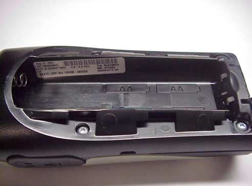
Click to zoom
Application Details
- Equipment Class
- TNF - Licensed Non-Broadcast Transmitter Held to Face
- Date of Grant
- Nov 15, 2001
- Application Purpose
- Original Equipment
- Date of Application
- Aug 29, 2001
- Equipment Note
- XTN Series Two-Way Radio
- Frequency Range
- 460.00000000 - 470.00000000
- Company
- Motorola Solutions, Inc.
- Country
- United States
Documents & Files
Document Text
Text extracted from the exhibit documents filed with the FCC. Open a document above to read the original.
Users Manual
PRELIMINARY @6864110R04@ 6864110R04-O 010449-O Models XU1100, XU2100, and XU2600 Models XV1100, XV2100, and XV2600 TWO-WAY RADIO User's Guide 6881038B80.book Page 1 Thursday, August 30, 2001 5:33 PM 6881038B80.book Page 2 Thursday, August 30, 2001 5:33 PM Safety and General Information i PRELIMINARY Safety and General InformationImportant Information on Safe and Efficient OperationRead This Information Before Using Your RadioThe information provided in this document supersedes the general safety information contained in user guides published prior to July 2000. For information regarding radio use in a hazardous atmosphere please refer to the Factory Mutual (FM) Approval Manual Supplement or Instruction Card, which is included with radio models that offer this capability.RF Operational CharacteristicsYour radio contains a transmitter and a receiver. When it is ON, it receives and transmits radio frequency (RF) energy. The XTN Series VHF radios operate in the frequency range of 151-161 MHz, the XTN Series UHF radios operate in the frequency range of 461-469 MHz. When you communicate with XU1100 or XV1100 radios the output power level is 1.0 watt, with other XTN Series radios, the output power level is 2.0 watts Exposure to Radio Frequency EnergyYour Motorola radio is designed to comply with the following national and international standards and guidelines regarding exposure of human beings to radio frequency electromagnetic energy:• United States Federal Communications Commission, Code of Federal Regulations; 47 CFR part 2 sub-part J • American National Standards Institute (ANSI) / Institute of Electrical and Electronic Engineers (IEEE) C95. 1-1992 • Institute of Electrical and Electronic Engineers (IEEE) C95.1-1999 Edition 6881038B80.book Page i Thursday, August 30, 2001 5:33 PM Safety and General Information ii PRELIMINARY • National Council on Radiation Protection and Measurements (NCRP) of the United States, Report 86, 1986 • International Commission on Non-Ionizing Radiation Protection (ICNIRP) 1998 • Ministry of Health (Canada) Safety Code 6. Limits of Human Exposure to Radio Frequency Electromagnetic Fields in the Frequency Range from 3 kHz to 300 GHz, 1999 • Australian Communications Authority Radiocommunications (Electromagnetic Radiation - Human Exposure) Standard 1999 (applicable to wireless phones only) To assure optimal radio performance and make sure human exposure to radio frequency electromagnetic energy is within the guidelines set forth in the above standards, always adhere to the following procedures:Portable Radio Operation and EME ExposureAntenna CareUse only the supplied or an approved replacement antenna. Unauthorized antennas, modifications, or attachments could damage the radio and may violate FCC regulations.DO NOT hold the antenna when the radio is “IN USE.” Holding the antenna affects the effective range.Two-Way Radio OperationWhen using your radio as a traditional two-way radio, hold the radio in a vertical position with the microphone two to three inches (5. 0 to 7.5 cm) away from the lips. 6881038B80.book Page ii Thursday, August 30, 2001 5:33 PM Safety and General Information iii PRELIMINARY Body-Worn OperationTo maintain compliance with FCC/Health Canada RF exposure guidelines, if you wear a radio on your body when transmitting, always place the radio in a Motorola supplied or approved clip, holder, holster, case, or body harness for this product. Use of non-Motorola-approved accessories may exceed FCC RF exposure guidelines. If you do not use a body-worn accessory, ensure the radio and its antenna is at least one inch (2.5 cm) from your body when transmitting . Data OperationWhen using any data feature of a device, with or without an accessory cable, position the device and its antenna at least one inch (2.5 cm) from the body.Approved AccessoriesFor a list of approved Motorola accessories refer to the Two-Way Radio section of www.motorola.com/store . Electromagnetic Interference/CompatibilityNote: Nearly every electronic device is susceptible to electromagnetic interference (EMI) if inadequately shielded, designed or otherwise configured for electromagnetic compatibility. FacilitiesTo avoid electromagnetic interference and/or compatibility conflicts, turn off your radio in any facility where posted notices instruct you to do so. Hospitals or health care facilities may be using equipment that is sensitive to external RF energy.AircraftWhen instructed to do so, turn off your radio when on board an aircraft. Any use of a radio must be in accordance with applicable regulations per airline crew instructions. 6881038B80.book Page iii Thursday, August 30, 2001 5:33 PM Safety and General Information iv PRELIMINARY Medical DevicesPacemakersThe Advanced Medical Technology Association recommends that a minimum separation of 6 inches (15 centimeters) be maintained between a handheld wireless radio and a pacemaker. These recommendations are consistent with the independent research by, and recommendations of the U.S. Food and Drug Administration.Persons with pacemakers should:• ALWAYS keep the radio more than six inches (15 centimeters) from their pacemaker when the radio is turned ON. • not carry the radio in the breast pocket. • use the ear opposite the pacemaker to minimize the potential for interference. • turn the radio OFF immediately if you have any reason to suspect that interference is taking place. Hearing AidsSome wireless radios may interfere with some hearing aids. In the event of such interference, you may want to consult your hearing aid manufacturer to discuss alternatives.Other Medical DevicesIf you use any other personal medical device, consult the manufacturer of your device to determine if it is adequately shielded from RF energy. Your physician may be able to assist you in obtaining this information. 6881038B80.book Page iv Thursday, August 30, 2001 5:33 PM Safety and General Information v PRELIMINARY Safety and General Use While DrivingCheck the la…
Text truncated - open the document above for the full version.
Attestation Statements
FCC ID: AZ489FT4851 STATEMENT OF CERTIFICATION The technical data supplied with this application, having been taken under my supervision is hereby duly certified. The following is a statement of my qualifications: 1) B.S.E.E. University of Miami. 2) M.E University Of Florida. 3) 7 years of Design and Development experience in the field of two-way radio communications. Name: Wayne Phang Signature: /s/ Wayne Phang Date: August 20, 2001 Position: Lead Electrical Dev. Engineer I hereby certify that the above application was prepared under my direction and that to the best of my knowledge and belief, the facts set forth in the application and accompanying technical data are true and correct: Name: Lorenzo Cruger Signature: /s/ Lorenzo Cruger Date: August 20, 2001 Position: Engineering Manager EXHIBIT 2
Cover Letter(s)
FCC ID: AZ489FT4851 Global Technology Development Group 8000 West Sunrise Boulevard, Fort Lauderdale, Florida 33322. (954) 723-5000 29 th August 2001 Authorization and Evaluation Division Federal Communications Commission Laboratory 7435 Oakland Mills Road Columbia. MD 21046 Subject: Application for Certification of Transmitter with FCC ID: AZ489FT4851. Gentlemen: Motorola Inc, 8000 West Sunrise Boulevard, Fort Lauderdale, Florida, herein submits application for Certification of the subject transmitter. This transmitter is primarily intended for use in a portable radio application with capabilities for clear communications with transmit output power of 1.0 and 2.2 Watts (30 dBm and 33.4 dBm). The subject transmitter complies with Section 90.203 of the rules in that the operator cannot directly program transmit frequencies using only the unit’s normally accessible external controls. Enclosed is a complete Type Acceptance Application. Contact me (954) 723-5793 or Fax me at (954) 723-4794, if you require any additional information. Sincerely, /s/ Mike Ramnath. FCC Liaison. Email: [email protected]
Cover Letter(s)
Applicant: Motorola Inc. FCC ID: AZ489FT4851 Motorola Inc., 8000 W. Sunrise Blvd., Plantation, FL 33322 Page: 13-2 REQUEST FOR CONFIDENTIALITY 29 August 2001 Authorization & Evaluation Division Federal Communications Commission Laboratory 7435 Oakland Mills Road Columbia, MD 21046 Subject: Application for Type Acceptance of Transmitter with FCC ID: AZ489FT4851. Gentlemen; Motorola is requesting that Exhibit 4 (Circuit Description), Exhibit 5 (Schematic Diagrams), Exhibit 9 (Internal Photographs) and Exhibit 10 (Semiconductor/Active Device List) not be made routinely available for public inspection. Motorola is in the process of licensing the technology and has a number of Patent applications pending. Please mark Exhibit 4, 5, 9 and 10 as Confidential. Contact me at (954) 723-5793 if you require any additional information. Regards, /s/ Mike Ramnath FCC Liaison Email: [email protected]
Cover Letter(s)
Applicant: Motorola Inc. FCC ID: AZ489FT4851 Motorola Inc., 8000 W. Sunrise Blvd., Plantation, FL 33322 Page: 13-2 REQUEST FOR CONFIDENTIALITY 24th October 2001 Authorization & Evaluation Division Federal Communications Commission Laboratory 7435 Oakland Mills Road Columbia, MD 21046 Subject: Application for Type Acceptance of Transmitter with FCC ID: AZ489FT4851. Gentlemen; Motorola is requesting that Exhibit 4 (Circuit Description), Exhibit 5 (Schematic Diagrams), and Exhibit 10 (Semiconductor/Active Device List) not be made routinely available for public inspection. Motorola is in the process of licensing the technology and has a number of Patent applications pending. Please mark Exhibit 4, 5, and 10 as Confidential. Contact me at (954) 723-5793 if you require any additional information. Regards, /s/ Mike Ramnath FCC Liaison Email: [email protected]
Cover Letter(s)
FCC ID: AZ489FT4851 24 th October 2001 Mr. Martin Perrine Authorization & Evaluation Division Federal Communications Commission Laboratory 7435 Oakland Mills Road Columbia, MD 21046 Re: Form 731 Confirmation Number: EA102194 with FCC ID: AZ489FT4851. Dear Mr. Perrine; Motorola Inc., 8000 West Sunrise Boulevard, Fort Lauderdale, Florida 33322, herein submits its response to the 19 th October 2001request for information in Correspondence Number 20994. Q1.) Revised letter of confidentiality. Internal photographs cannot be held confidentially without specific and strong justification. R1.) Attached is a corrected Confidentiality Request (Exhibit 13a) deleting Exhibit 9, Internal Photos. Q2.) Test setup photographs for the radiated tests if available. Per Section 2.947(e). R2.) EMC Open Air Test Site (OATS) Lab, Plantation, Florida showing Radiated Test Setup. Unit Under Test Rotating Turntable Adjustable Antenna FCC ID: AZ489FT4851 Q3.) Certificate stating compliance with spectral efficiency per Section 90.203(j)(3). R3.) This radio is capable of operating in either 12.5 kHz or 25 kHz channel spacing mode depending on the frequency as specified in the frequency table on page 30 of the Users Manual. The radio meets Emission Mask “D” for 12.5 kHz and Emission Mask “B” for 25 kHz mode and are included in the original application as Exhibits 6D-1 to 6D-8. Frequencies that are specified by the FCC for only 12.5 kHz or 25 kHz operation are fixed to the prescribed bandwidth and cannot be changed by the user. Q4.) New data for the field strength of spurious radiation. Please provide the data in the form of decibels relative to the carrier power measured in ERP (dBc) as standard using the "Substitution" method as described in TIA/EIA-603. Please include a measurement of the reference level. R4.) It is our interpretation that spurious emissions are supposed to meet absolute minimum values, mainly that they are supposed to be below a – 20 dBm limit. Exhibit 6E1 through 6E-4 in the original application show that the radiated spurious emissions are way below the –20 dbm specification. Reference level is 0dbm since these are absolute readings. Spurious emissions are measured using a non-radiating dummy load as per TIA/EIA-603 in order to insure no overloading of measuring test equipment. For reference only, we measured ERP of a 2 Watt radio. The results are shown below: Average Radiated Output PowerTechnician:Bill Quigley s/n: 158ABQ0834Date: 10/23/2001 model: XU2600 Frequency: 464.5625 MHz Receive Ant:Sig. Gen Out (dBm):0 Sub. Ant:Cable Loss (dB):7.54 Tx Ant. Gain Vpol (dBd):-1.05 Horizontal Polarization Vertical PolarizationTx Output (dBm):-8.59 Azimuth AmplitudeCorrectedAzimuthAmplitudeCorrected Analyzer Reading (dBm):-40.06 (Deg)(dBm)(dB)(Deg)(dBm)(dB)Tx Pathloss (dB)-31.47 0-10.03 139.320-8.15214.78 45-13.99 55.97645-6.13341.98 90-24.455.03590-6.89287.08Hpo l 135-11.599.312135-6.4321.37Avg. Rad. Pow. (dBm): 27.75034 180-9.52156.68180-8.48199.07 225-13.8957.28225-6.37323.59Vpo l 270-30.03 1.3932270-7.04277.33Avg. Rad. Pow. (dBm): 33.62491 315-12.480.724315-6.17338.84 g. Rad. Power (dBm) 27.75Rad. Power (dBm) 33.625 FCC ID: AZ489FT4851 Q5.) Clarification of the units maximum power. Page 9 of the SAR report states that with the NiMH battery the maximum power is 2.48 W. The maximum power mentioned in the EMC report is 2.2 W. Please provide additional test data if needed to reflect the units maximum power. R5.) The EMC RF POWER OUTPUT DATA of exhibit 6A represents a production radio which was pre-adjusted, per production alignment procedures, to the maximum transmit power, defined as the production line final test station upper limit, which in this case is 2.2 Watts. The Transmitter Radiated Spurious Emissions data are taken with the same radio using a fully charged NiMH battery. However, due to the higher than nominal initial voltage typical with a fully charged NiMH battery, and the difference in series impedance based on the battery chemistry, the maximum transmit power used is based on the maximum power achievable with each individual battery type. In this case, the maximum transmit power of the XCU2600 radio with the NiMH 53871 rechargeable battery is 2.48 Watts. In the SAR report, the max power reported is the initial maximum power seen during power slump measurements taken with a NiMH battery. The typical power is 2.1 Watts as can be seen in the figure below. This maximum power is within the maximum allowable power variation (20%). Q6.) A discussion about the expected variation in unit performance for both the NIMH and Alkaline battery options discussed in the User Manual. Please address expected frequency stability over the usable range of the battery voltage. Toronto 2Watt NiMH Freq 33 464.5625Mhz S/N: 158ABN0012 1.800 1.900 2.000 2.100 2.200 2.300 2.400 2.500 2.600 0 2 4 6 8 10 12 14 16 18 20 22 24 26 28 30 32 34 36 38 40 Time Power out Series1 FCC ID: AZ489FT4851 R6.) The radio has two internal regulators and a voltage clamp circuit that address variations on input supply voltage. The regulators are labeled as VCC and Dig_VCC, the clamped voltage is labeled VCLAMP on the schematics included in Section V. The regulators have a temperature and voltage compensated output voltage of 2.5 Volts. These regulators are used to supply the frequency generation unit (reference oscillator, VCO, Synthesizer). Since two battery sources are possible, NIMH or Alkaline, the clamp circuit is used to limit the high voltage seen by the regulators (4.0 Volts in Tx and 4.5 Volts in Rx), this is mainly needed when Alkaline batteries are used. On the low side the batteries can potentially be used to 3.6 Volts (0.9 Volts per cell). However to minimize possible pre-mature battery death due to deep discharges (which can happen if the radio is left on and unattended for extended periods of time), the radio software automatically shuts down the radio when the battery voltage drops below 4.0 Volts. Exhibit 6G-2 and 6G-3 show…
Text truncated - open the document above for the full version.
Cover Letter(s)
FCC ID: AZ489FT4851 2 nd November 2001 Mr. Martin Perrine Authorization & Evaluation Division Federal Communications Commission Laboratory 7435 Oakland Mills Road Columbia, MD 21046 Re: Form 731 Confirmation Number: EA102194 with FCC ID: AZ489FT4851. Dear Mr. Perrine; Motorola Inc., 8000 West Sunrise Boulevard, Fort Lauderdale, Florida 33322, herein submits its response to the 19 th October 2001request for information in Correspondence Number 20994. Q1.) Revised letter of confidentiality. Internal photographs cannot be held confidentially without specific and strong justification. R1.) Attached is a corrected Confidentiality Request (Exhibit 13a) deleting Exhibit 9, Internal Photos. Q2.) Test setup photographs for the radiated tests if available. Per Section 2.947(e). R2.) EMC Open Air Test Site (OATS) Lab, Plantation, Florida showing Radiated Test Setup. Unit Under Test Rotating Turntable Adjustable Antenna FCC ID: AZ489FT4851 Q3.) Certificate stating compliance with spectral efficiency per Section 90.203(j)(3). R3.) This radio is capable of operating in either 12.5 kHz or 25 kHz channel spacing mode depending on the frequency as specified in the frequency table on page 30 of the Users Manual. The radio meets Emission Mask “D” for 12.5 kHz and Emission Mask “B” for 25 kHz mode and are included in the original application as Exhibits 6D-1 to 6D-8. Frequencies that are specified by the FCC for only 12.5 kHz or 25 kHz operation are fixed to the prescribed bandwidth and cannot be changed by the user. Q4.) New data for the field strength of spurious radiation. Please provide the data in the form of decibels relative to the carrier power measured in ERP (dBc) as standard using the "Substitution" method as described in TIA/EIA-603. Please include a measurement of the reference level. R4.) It is our interpretation that spurious emissions are supposed to meet absolute minimum values, mainly that they are supposed to be below a – 20 dBm limit. Exhibit 6E1 through 6E-4 in the original application show that the radiated spurious emissions are way below the –20 dbm specification. Reference level is 0dbm since these are absolute readings. Spurious emissions are measured using a non-radiating dummy load as per TIA/EIA-603 in order to insure no overloading of measuring test equipment. For reference only, we measured ERP of a 2 Watt radio. The results are shown below: Average Radiated Output PowerTechnician:Bill Quigley s/n: 158ABQ0834 Date: 10/23/2001 model: XU2600 Frequency: 464.5625 MHz Receive Ant:Sig. Gen Out (dBm):0 Sub. Ant:Cable Loss (dB):7.54 Tx Ant. Gain Vpol (dBd):-1.05 Horizontal PolarizationVertical Polarization Tx Output (dBm):-8.59 AzimuthAmplitudeCorrectedAzimuthAmplitudeCorrected Analyzer Reading (dBm):-40.06 (Deg)(dBm)(dB)(Deg)(dBm)(dB)Tx Pathloss (dB)-31.47 0-10.03 139.320-8.15214.78 45-13.99 55.97645-6.13341.98 90-24.455.03590-6.89287.08Hpol 135-11.599.312135-6.4321.37 Avg. Rad. Pow. (dBm): 27.75034 180-9.52156.68180-8.48199.07 225-13.8957.28225-6.37323.59 Vpol 270-30.03 1.3932270-7.04277.33 Avg. Rad. Pow. (dBm): 33.62491 315-12.480.724315-6.17338.84 g. Rad. Power (dBm)27.75Rad. Power (dBm)33.625 FCC ID: AZ489FT4851 Q5.) Clarification of the units maximum power. Page 9 of the SAR report states that with the NiMH battery the maximum power is 2.48 W. The maximum power mentioned in the EMC report is 2.2 W. Please provide additional test data if needed to reflect the units maximum power. R5.) The EMC RF POWER OUTPUT DATA of exhibit 6A represents a production radio which was pre-adjusted, per production alignment procedures, to the maximum transmit power, defined as the production line final test station upper limit, which in this case is 2.2 Watts. The Transmitter Radiated Spurious Emissions data are taken with the same radio using a fully charged NiMH battery. However, due to the higher than nominal initial voltage typical with a fully charged NiMH battery, and the difference in series impedance based on the battery chemistry, the maximum transmit power used is based on the maximum power achievable with each individual battery type. In this case, the maximum transmit power of the XCU2600 radio with the NiMH 53871 rechargeable battery is 2.48 Watts. In the SAR report, the max power reported is the initial maximum power seen during power slump measurements taken with a NiMH battery. The typical power is 2.1 Watts as can be seen in the figure below. This maximum power is within the maximum allowable power variation (20%). Toronto 2Watt NiMH Freq 33 464.5625Mhz S/N: 158ABN0012 1.800 1.900 2.000 2.100 2.200 2.300 2.400 2.500 2.600 0 2 4 6 8 10 12 14 16 18 20 22 24 26 28 30 32 34 36 38 40 Time Power out Series1 FCC ID: AZ489FT4851 XTN UHF AA 2Watts CH2 464.5625 MHz S/N: 158ABS0701 0.000 0.500 1.000 1.500 2.000 2.500 024 68 10 12 14 16 18 20 22 24 26 28 30 32 34 36 38 40 Time Power Out Series1 Q6.) A discussion about the expected variation in unit performance for both the NIMH and Alkaline battery options discussed in the User Manual. Please address expected frequency stability over the usable range of the battery voltage. R6.) The radio has two internal regulators and a voltage clamp circuit that address variations on input supply voltage. The regulators are labeled as VCC and Dig_VCC, the clamped voltage is labeled VCLAMP on the schematics included in Section V. The regulators have a temperature and voltage compensated output voltage of 2.5 Volts. These regulators are used to supply the frequency generation unit (reference oscillator, VCO, Synthesizer). Since two battery sources are possible, NIMH or Alkaline, the clamp circuit is used to limit the high voltage seen by the regulators (4.0 Volts in Tx and 4.5 Volts in Rx), this is mainly needed when Alkaline batteries are used. On the low side the batteries can potentially be used to 3.6 Volts (0.9 Volts per cell). However to minimize possible pre-mature battery death due to deep discharges (which can happen if the radio is left on and unatte…
Text truncated - open the document above for the full version.
Cover Letter(s)
8 th November 2001 Mr. Martin Perrine Authorization & Evaluation Division Federal Communications Commission Laboratory 7435 Oakland Mills Road Columbia, MD 21046 Re: Form 731 Confirmation Number: EA102194 with FCC ID: AZ489FT4851. Dear Mr. Perrine; Motorola Inc., 8000 West Sunrise Boulevard, Fort Lauderdale, Florida 33322, herein submits its response to the 7 th November 2001 Correspondence Number 21183. Q1) Justification for authorization of the two models mentioned in this filing, each having a distinct power level, to be issued under one FCC ID. CFR 47 Section 2.1043(a) requires that radios having different maximum power outputs must have separate ID's. Since the power is set at the factory and each unit has a fixed power level (either 1 W or 2 W) the FCC considers these two separate radios and thus requires two FCC ID's. It was noted from the circuit description in your exhibit 4D that the PA matching output components are different for the two maximum power levels. If you agree, please specify which maximum power level you would like to have filed on this R1) With respect to the possible use of two FCC ID numbers, Exhibit 4 may be confusing. In fact, the PA matching output components are not different for the two maximum power levels. If one were to look at the boards of the two radios, from a hardware standpoint, the circuits are identical. The difference in the models is simply in the way the radios are adjusted during manufacturing. For that reason, we provided data at both power levels. We regret any confusion that Exhibit 4 caused, but the approach we propose really does not result in two different devices. In the past, the Commission has routinely approved radios in which the user could change the output power. Similarly, we have had radios approved in w hich the manufacturer could select the output power from the powers specified on the grant of equipment authorization, but the user could not change the output power. The application under review is an example of the latter. Because this unit is one radio, we respectfully ask that if be approved with a note on the grant explaining that the power is factory set at either one watt or two watts. Such a condition should eliminate any confusion as to the nature of the device. Q2) Sample calculation for your response to question 4 in your correspondence dated 2 nd November 2001. R2) As discussed, the following is sent to you as an “FYI” because the response provided to the FCC in Correspondence 20994 was based on a misinterpretation of Question 4 as asked. Please see the sample calculation of the Average Radiated power in the table below. The measurement unit for the “Corrected Amplitude” column was incorrect in the data sent previously and should have been in mW instead of dB. Sample calculation (Vertical Polar ization) : Amplitude at 0 Deg = -8.15 dBm Corrected Amplitude = -8.15 dBm – (Tx Pathloss) = -8.15 – (-31.47) = 23.32 dBm = 10^(23.32/10) mW = 214.78 mW Avg. Rad Power = sum of the 6 corrected amplitude from 0 – 315 Deg. (expressed in dBm) = 10x log (214.78+341.98+287.08+321.37+199.07+323.59+277.33+338.84) = (10x log 2304.04) dBm = 33.625 dBm Contact me at (954) 723-5793 if you require any additional information. Regards, /s/ Mike Ramnath FCC Liaison Email: [email protected] Average Radiated Output Power Technician:Bill Quigley s/n: 158ABQ0834 Date: 10/23/2001 model: XU2600 Frequency: 464.5625 MHz Receive Ant:Sig. Gen Out (dBm):0 Sub. Ant:Cable Loss (dB):7.54 Tx Ant. Gain Vpol (dBd):-1.05 Horizontal PolarizationVertical PolarizationTx Output (dBm):-8.59 AzimuthAmplitude CorrectedAzimuth Amplitude CorrectedAnalyzer Reading (dBm):-40.06 (Deg)(dBm)(mW)(Deg)(dBm)(mW)Tx Pathloss (dB)-31.47 0-10.03139.320-8.15214.78 45-13.9955.9845-6.13341.98 90-24.455.0490-6.89287.08 Hpol 135-11.599.31135-6.4321.37 Av g. Rad. Pow. (dBm):27.75034 180-9.52156.68180-8.48199.07 225-13.8957.28225-6.37323.59 Vpol 270-30.031.39270-7.04277.33 Av g. Rad. Pow. (dBm):33.62491 315-12.480.72315-6.17338.84 Avg. Rad. Power (dBm) 27.75034Avg. Rad. Power (dBm)33.625
External Photos
FCC ID: AZ489FT4851 EXTERNAL PHOTOGRAPHS: 1 Front view of Radio. 2 Rear view of radio without battery cover. 3 Magnified view of FCC Label. EXHIBIT 3 FCC ID: AZ489FT4851 EXHIBIT 3-1 FCC ID: AZ489FT4851 EXHIBIT 3-2 FCC ID: AZ489FT4851 EXHIBIT 3-3
ID Label/Location Info
FCC ID: AZ489FT4851 LIST OF EXHIBITS DESCRIPTION EXHIBIT REFERENCE I. Identification label information 1 2.983-(f) & General Information 1a 1. Production Plans 2.981-(a) 2. Application References 2.1061 3. Data Submittal Procedure 4. Similar Applications II. Certification of Data 2 III. External Photographs 3 2.983-(g) IV. Block Diagrams 4 1. Frequency Stabilizing 4A 2. Modulation Limiting 4B and Post Limiter Filter 3.Harmonic Suppression 4C 4.Power Limiting 4D V. Schematic Diagrams 5 2.983-(d)-7 VI. Test Report 6 1. Data Index 6 2. RF Output Data 6A 2.985 3. Modulation Characteristics 2.987 A. Audio Response & Low Pass Filter Response 6B, 9C B. Modulation Limiting 6D 4. Occupied Bandwidth 6E 2.989 5. Conducted Spurious Emissions 6F 2.991 6. Radiated Spurious Emissions 6G 2.993 7. Frequency Stability (Temperature & Supply Voltage) 6H-1, 9H-2 2.995 8. Transient Frequency Behavior 6I 90.214 VII. Test Set-up Procedures 7 2.999 VIII. Instruction Manual 8 2.983-(d)-8 IX. Internal Photographs. 9 2.983-(g) X. Parts List and Tune-Up procedures 10 2.983-(d)-6, 9 XI. RF Exposure Information 11 2.1093 XII. Operational Description 12 2.983-(d)1,2,3,4,5 1. Technical Characteristics 2. Application XIII. Cover Letter 13 FCC ID: AZ489FT4851 IDENTIFICATION LABEL LOCATION X See the attached Photograph, and exhibit 3 for the location of the label on the device Back of Radio Back of Radio under Belt Clip TYPE X The label is a paper polyester film laminate with a pressure sensitive adhesive backing. The adhesive is a permanent type acrylic with minimum peel strength of 40oz/ inch. The label is laser etched into the Urethane paint, exposing the Nickel plating on the Zamak casting substrate. Since no adhesive is required, the label is permanent and tamper-proof. (** - NOTE- The label attached below is a paper polyester film laminate, as described above. This is just for sample purposes, as the actual label is laser etched into the casting) MARKINGS (TEXT) See Photograph, Exhibit 1. EXHIBIT 1 FCC ID: AZ489FT4851 GENERAL INFORMATION I. Production Plans—Pursuant 2.983 ( c ). Quantity production is planned. II. Application References -- Pursuant 2.1061 Reference is made to the following Motorola “Application References” 1. Portable Products and their application. 2. Portable Products Transmitter Modulations Methods. III. Data Submittal Procedure: Data is supplied in accordance with Part 2, Sub-part J of the Commissions’ Rules. IV. Similar, currently Type Accepted Transmitter, FCC ID: AZ489FT4818. EXHIBIT 1A
ID Label/Location Info
FCC ID: AZ489FT4851 IDENTIFICATION LABEL LOCATION X See the attached Photograph, and exhibit 3 for the location of the label on the device Back of Radio Back of Radio under Belt Clip TYPE X The label is a paper polyester film laminate with a pressure sensitive adhesive backing. The adhesive is a permanent type acrylic with minimum peel strength of 40oz/ inch. The label is laser etched into the Urethane paint, exposing the Nickel plating on the Zamak casting substrate. Since no adhesive is required, the label is permanent and tamper-proof. (** - NOTE- The label attached below is a paper polyester film laminate, as described above. This is just for sample purposes, as the actual label is laser etched into the casting) MARKINGS (TEXT) See Photograph, Exhibit 1. EXHIBIT 1
Internal Photos
FCC ID: AZ489FT4851 CONFIDENTIALITY REQUESTED INTERNAL PHOTOGRAPHS: 1 Component side, View of PC Board EXHIBIT 9-A 2 Non Component side, of PC Board EXHIBIT 9-B EXHIBIT 9 FCC ID: AZ489FT4851 EXHIBIT 9-A FCC ID: AZ489FT4851 EXHIBIT 9-B
Operational Description
FCC ID: AZ489FT4851 OPERATIONAL DESCRIPTION I. Transmitter Technical Characteristics—Pursuant 2.983 (d) A. RF Power Output 1.0 Watt / 2.2 Watt B. Frequency Range 460-470 MHz C. Frequency Stability 0.00025 % D. Emissions Designators 11K0F3E, 16K0F3E(see General Info.) E. Spurious Emissions 76.1dBc F. DC Voltage and Current into 4.8 Volts the final RF amplifier stage/stages 1 Watt /570mAmps 2 Watt/ 820mAmps II. Transmitter Application This transmitter…
Text truncated - open the document above for the full version.
Contact Information
Applicant
Deanna Zakharia(Regulatory Compliance Manager)
Technical Contact
Motorola IncMike Ramnath
[email protected]954-723-5793
8000 West Sunrise Blvd · Ft. Lauderdale, Florida · United States
Technical Specifications
| # | Rule Parts | Frequency Range | Power Output | Emission | Tolerance |
|---|---|---|---|---|---|
| 4 | 9 | 460 MHz - 470 MHz | 1.2 W | 11K0F3E | 2.5 ppm |
Other Applications from Motorola Solutions, Inc.

AZ489FT4980
Sep 08, 2026Portable two way radio
Equipment Class
TNF - Licensed Non-Broadcast Transmitter Held to FaceAZ489FT4981
Aug 14, 2026Handheld Portable - TANAPA BPR 45 400-470 MHZ 4W NKP
Equipment Class
TNF - Licensed Non-Broadcast Transmitter Held to Face
AZ489FT7187
Jul 13, 2026Portable 2-Way Radio with Bluetooth, Bluetooth LE, WIFI 2.4GHz, WIFI 5GHz, LTE
Equipment Class
DSS - Part 15 Spread Spectrum TransmitterAZ499FT6031
May 11, 2026Operation Critical Wireless Earpiece PTT
Equipment Class
DSS - Part 15 Spread Spectrum Transmitter
AZ499FT5879
Dec 19, 20252-way Portable Radio with BT, BTLE, WIFI, NFC and LTE
Equipment Class
DSS - Part 15 Spread Spectrum Transmitter