AZ489FT4864XTS5000 UHF R-2
Motorola Solutions, Inc.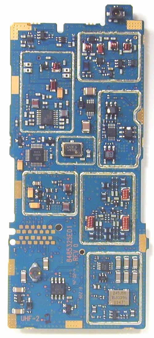
Click to zoom
Application Details
- Equipment Class
- TNF - Licensed Non-Broadcast Transmitter Held to Face
- Date of Grant
- Mar 31, 2004
- Application Purpose
- Original Equipment
- Date of Application
- Mar 31, 2004
- Equipment Note
- XTS5000 UHF R-2
- Frequency Range
- 450.00000000 - 520.00000000
- Company
- Motorola Solutions, Inc.
- Country
- United States
Documents & Files
Document Text
Text extracted from the exhibit documents filed with the FCC. Open a document above to read the original.
Users Manual
ASTRO ® XTS TM 5000 Digital Portable Radio Model III User Guide ASTRO ® XTS ™ 5000 Digital Portable Radio, Model III Quick Reference Card Product Safety and RF Exposure Compliance ATTENTION! This radio is restricted to occupational use only to satisfy FCC RF energy exposure requirements. Before using this product, read the RF energy awareness information and operating instructions in the Product Safety and RF Exposure booklet enclosed with your radio (Motorola Publication part number 68P81095C98) to ensure compliance with RF energy exposure limits. Write your radio’s programmed features on the dashed lines. Radio On/OffZones/ChannelsReceive/TransmitSend Emergency Alarm Send Emergency CallSend Silent Emergency Alarm Before using this product, read the operating instructions for safe usage contained in the Product Safety and RF Exposure booklet enclosed with your radio. ! C a u t i o n 16-Position Select Knob _ _ _ _ _ _ _ Speaker/Mic Top Button _ _ _ _ _ _ _ Concentric Switch_ _ _ _ _ _ Display Keypad Menu Select ButtonsApp Button (for future use) Top Side Button_ _ _ _ _ _ _On/Off/Volume Knob Side Button 1_ _ _ _ _ _ _Side Button 2_ _ _ _ _ _ _ PTT Button 3-Position Switch _ _ _ _ _ _ _ 4-WayNavigation ButtonHome Button 1On - On/Off/Volume knob clockwise. 2Off - On/Off/Volume knob counterclockwise. 1 Zone - Zone switch to desired zone. 2 Channel - Channel switch to desired channel. 1 Radio on and select zone/channel. 2 Listen for a transmission. - or -Press and hold Volume Set button. - or -Press Monitor button and listen for activity. 3 Adjust volume, if necessary. 4Press PTT to transmit; release to receive. Radio on and press Emergency button. Display shows current zone/channel, andEMERGENCY . Red LED lights; you hear short, medium-pitched tone. Note: To exit emergency at any time, press and hold Emergency button. When acknowledgment is received, you hear four beeps; alarm ends; radio exits emer-gency. 1 Radio on and press Emergency button. Note: To exit emergency at any time, press and hold Emergency button. 2 Press and hold PTT . Announce your emergency into the microphone. 3 Release PTT to end call. 4 Press and hold Emergency button to exit emergency. 1 Radio on and press Emergency button. Display does not change; you see no LED; you hear no tone. Note: To exit emergency at any time, press and hold Emergency button. 2 Silent emergency continues until you: • Press and hold Emergency button to exit emergency state.- or - • Press and release PTT to exit silent emergency and enter regular emergency (alarm, call, or alarm with call). Display Status Symbols Menu Entries (Use With Menu Navigation) m Receiving an individual call p The radio is in the view or program mode; On Steady = view mode; Flashing = program mode s Received signal strength for the current site (trunking only). The more stripes in the symbol, the stronger the signal. b Flashes when the battery is low. r You are talking directly to another radio or through a repeater; On = direct; Off = repeater C This channel is being monitored. c Your radio is in secure operation; On = secure operation; Off = clear operation; Flashing = receiving an encrypted voice call T The radio is scanning a scan list S Priority 1 Channel during scan S Priority 2 Channel during scan Entry Menu Selection Page BATT Smart Battery 16 CALL Private Call /Selective Call 59/63 CHAN Select a Channel 22 CLCK Set the Time and Date 95 DIR Repeater/Direct 74 ERAS Key Zeroization 82 KEY Key Selection 79 KSET Keyset Selection 80 LOGF Radio Lock 31 MUTE Keypad Mute 32 NAME Text Select 42 NUM Number Select 41 Entry Menu Selection Page PAGE Call Alert Page 67 PHON Phone 55 PROG Editing 41 PSWD Password 30 PWR TX Power Level 27 REKY Rekey Request 85 RPGM Reprogram Request 88 SCAN Scan On/Off 51 SITE Site Lock/Unlock 92 STS Status Call 72 TGRP Talkgroup Call 70 VIEW View a List 40 ZONE Select a Zone 21 Menu Navigation U to find Menu Entry D , or E , or F directly below Menu Entry to select h to exit V or U to scroll through sub-list D , or E , or F directly below Menu Entry to select ASTRO ® XTS ™ 5000 Digital Portable Radio Model III User Guide 6881094C27-E Motorola, Inc. 8000 West Sunrise Blvd. Ft. Lauderdale, FL 33322 Product Safety and RF Exposure Compliance ATTENTION! This radio is restricted to occupational use only to satisfy FCC RF energy exposure requirements. Before using this product, read the RF energy awareness information and operating instructions in the Product Safety and RF Exposure booklet enclosed with your radio (Motorola Publication part number 68P81095C98) to ensure compliance with RF energy exposure limits. Computer Software Copyrights The Motorola products described in this manual may include copyrighted Motorola computer programs stored in semiconductor memories or other media. Laws in the United States and other countries preserve for Motorola certain exclusive rights for copyrighted computer programs, including, but not limited to, the exclusive right to copy or reproduce in any form the copyrighted computer program. Accordingly, any copyrighted Motorola computer programs contained in the Motorola products described in this manual may not be copied, reproduced, modified, reverse-engineered, or distributed in any manner without the express written permission of Motorola. Furthermore, the purchase of Motorola products shall not be deemed to grant either directly or by implication, estoppel, or otherwise, any license under the copyrights, patents or patent applications of Motorola, except for the normal non-exclusive license to use that arises by operation of law in the sale of a product. Documentation Copyrights No duplication or distribution of this document or any portion thereof shall take place without the express written permission of Motorola. No part of this manual may be reproduced, distributed, or transmitted in any form or by any means, electronic or mechanical, for any purpose without the express written permission of Motorola. Disc…
Text truncated - open the document above for the full version.
Users Manual
English Product Safety and RF Exposure for Portable Two-Way Radios The information provided in this document supersedes the general safety information contained in user guides published prior to February 2002. For radios that have been approved as intrinsically safe, read the instructions and information on intrinsic safety on page 9 of this booklet. Compliance with RF Energy Exposure Standards NOTICE: This radio is intended for use in occupational/controlled applications where users have been made aware of the potential for exposure and can exercise control over their exposure. This radio device is NOT authorized for general population, consumer or similar use. BEFORE USING THIS RADIO, READ THIS BOOKLET WHICH CONTAINS IMPORTANT OPERATING INSTRUCTIONS FOR SAFE USAGE AND RF ENERGY AWARENESS AND CONTROL INFORMATION FOR COMPLIANCE WITH RF ENERGY EXPOSURE LIMITS IN APPLICABLE NATIONAL AND INTERNATIONAL STANDARDS. ! C a u t i o n © Motorola, Inc. 2003 8000 W. Sunrise Blvd., Ft. Lauderdale, FL 33322 Printed in U.S.A. 3/03. *6881095C98* 68P81095C98-A 2 English Federal Communication Commission (FCC) Regulations The FCC has established limits for safe exposure to radio frequency (RF) emissions from portable two-way radios. The FCC requires manufacturers to demonstrate compliance with RF exposure limits before portable two-way radios can be marketed in the U.S. When two-way radios are approved for occupational/ controlled environment exposure limits, the FCC requires users to be fully aware of, and exercise control over, their exposure. Awareness and control of RF exposure can be accomplished by the use of labels, or by education and training through appropriate means, such as information and instructions in user manuals or safety booklets. Your Motorola two-way radio has an RF exposure information label in the battery compartment. This user safety booklet includes useful information about RF exposure and helpful instructions on how to control your RF exposure. Your Motorola two-way radio is designed and tested to comply with a number of national and international standards and guidelines (listed below) regarding human exposure to RF electromagnetic energy. This radio complies with the IEEE (FCC) and ICNIRP exposure limits for occupational/controlled RF exposure environments at usage factors of up to 50% talk–50% listen. In terms of measuring RF energy for compliance with FCC exposure guidelines, your radio radiates measurable RF energy only while it is transmitting (during talking), not when it is receiving (listening) or in standby mode. NOTE:The approved batteries, supplied with this radio, are rated for a 5-5-90 duty cycle (5% talk–5% listen–90% standby), even though this radio complies with FCC occupational exposure limits at usage factors of up to 50% talk. 3 English Your Motorola two-way radio complies with the following RF energy exposure standards and guidelines: • United States Federal Communications Commission, Code of Federal Regulations; 47CFR part 2 sub-part J • American National Standards Institute (ANSI) / Institute of Electrical and Electronic Engineers (IEEE) C95. 1-1992 • Institute of Electrical and Electronic Engineers (IEEE) C95.1-1999 Edition • International Commission on Non-Ionizing Radiation Protection (ICNIRP) 1998 • Ministry of Health (Canada) Safety Code 6. Limits of Human Exposure to Radiofrequency Electromagnetic Fields in the Frequency Range from 3 kHz to 300 GHz, 1999 • Australian Communications Authority Radiocommunications (Electromagnetic Radiation – Human Exposure) Standard, 2001 • ANATEL, Brasil Regulatory Authority, Resolution 256 (April 11, 2001) “additional requirements for SMR, cellular and PCS product certification.” Compliance and Control Guidelines and Operating Instructions for Portable Two-Way Radios To control your exposure and ensure compliance with the occupational/ controlled environment exposure limits, always adhere to the following procedures: • Transmit no more than 50% of the time. To transmit (talk), push the Push- To-Talk (PTT) button. To receive calls, release the PTT button. Transmitting 50% of the time or less is important since the radio generates measurable RF energy exposure only when transmitting (in terms of measuring standards compliance). 4 English • Hold the radio in a vertical position in front of the face with the microphone (and other parts of the radio including the antenna) at least one to two inches (2.5 to 5 centimeters) away from the lips. Keeping the radio at a proper distance is important since RF exposures decrease with increasing distance from the antenna. •For body-worn operation, always place the radio in a Motorola-approved clip, holder, holster, case, or body harness for this product. All Motorola- approved accessory, antenna, and device combinations comply with FCC occupational/controlled environment RF exposure limits. Exposure information on various accessory, antenna, and device combinations can be found under the “Display Exhibits” section of http://www.fcc.gov/oet/ fccid after searching on the FCC ID number, which can be obtained from the label of your radio. Using non–Motorola-approved accessories may result in exposure levels which exceed the FCC’s occupational/controlled environment RF exposure limits. • If you are not using a body-worn accessory and are not using the radio in the intended use position in front of the face, ensure the antenna and the radio are kept one inch (2.5 centimeters) from the body when transmitting. Keeping the radio at a proper distance is important since RF exposures decrease with increasing distance from the antenna. •Use only Motorola-approved supplied or replacement antennas, batteries, and accessories. Use of non–Motorola-approved antennas, batteries and accessories may exceed FCC RF exposure guidelines. For a list of Motorola- approved antennas, batteries, and other accessories, visit the following web site which lists approved accessories: http://www.motorola.com/cgiss/inde…
Text truncated - open the document above for the full version.
Cover Letter(s)
FCC ID: AZ489FT4864 ______________________________________________________________________________ Radio Products Group 8000 West Sunrise Boulevard, Fort Lauderdale, Florida 33322. (954) 723-5000 CONFIDENTIALITY REQUESTED Date: 29th March, 2004 Authorization & Evaluation Division Federal Communications Commission Laboratory 7435 Oakland Mills Road Columbia, MD 21046 Subject: Application for Type Acceptance of Transmitter with FCC ID: AZ489FT4864. Dear Sir or Madam: Motorola is requesting that Exhibit 4 (Circuit Descriptions), Exhibit 5 (Schematic Diagrams), Exhibit 10 (Parts List and Tune Up Procedures), and Exhibit 12 (Operational Description) not be made routinely available for public inspection. Motorola considers the information in these exhibits to be classified as trade secrets, pursuant to 47 CFR Section 0.457(d) and Section 552(b)(4) of the Freedom of Information Act. Please mark Exhibits 4, 5, 10, and 12 as “Confidential.” Please contact me if you require any additional information. Sincerely, /s/ Mike Ramnath (signed) Manager, Regulatory Compliance Tel: (954) 723-5793 E-mail: [email protected] EXHIBIT 13B
ID Label/Location Info
Applicant: Motorola Inc. FCC ID: AZ489FT4864 IDENTIFICATION LABEL LOCATION See the Attached Photograph or Sketch X Back of Radio Back of Radio under Belt Clip TYPE X The label is a paper polyester film laminate with a pressure sensitive adhesive backing. The adhesive is a permanent type acrylic with a minimum peel strength of 40 oz/inch. MARKINGS (TEXT) X See the Attached Photograph and Exhibit 3C for the actual location of the FCC label on the device. Label Attached Below. See Attached Drawing. EXHIBIT 1 Applicant: Motorola Inc. FCC ID: AZ489FT4864 GENERAL INFORMATION I. Production Plans -- Pursuant 2.1033 (c) Quantity production is planned. II. Application References -- Pursuant 2.1061 Reference is made to the following Motorola "Application References" 1. Portable Products and their application. 2. Portable Products Transmitter Modulations Methods. 3. Plantation, Florida Antenna Range. III. Data Submittal Procedure: Data is supplied in accordance with Part 2, Sub-part J of the Commissions’ rules. Necessary Bandwidth Computation for 8K10F1E Emission Designator The FCC Rule & Regulations Part 2, §2.202(b) defines Necessary Bandwidth as the minimum value of the occupied bandwidth sufficient to ensure that transmission of information at the rate and with the quality required for the system employed. §2.202(c) lists four methods of determining the necessary bandwidth, including the use of formulas in §2.202(g), and measurement in cases where the other methods of §2.202(c) do not apply. It is felt that while these formulas apply well to voice and many older digital modulation systems, the formulas do not apply to the high performance digital modulation employed in the system submitted for Certification because of difficulties determining representative values for the factors K and M. We have, therefore, used the measurement criteria of §2.202(c)(4). The value cited, 8K10, is the bandwidth that contains 99% of the total transmitted power. The 99% value was chosen because §2.202(b) defines Necessary Bandwidth as the minimum value of the occupied bandwidth . In turn, §2.202(b) defines Occupied Bandwidth as the frequency bandwidth such that, below its lower and above its upper frequency limits, the mean powers radiated are each equal to 0.5% of the total mean power radiated by a given emission, i.e., contains 99% of the total transmitted power. IV. Applicable References: • Reference Certification FCC ID: AZ489FT4864 • EIA/TIA-603 Land Mobile FM or PM Communications Equipment Measurement and Performance Standards • FCC Federal Regulations Part 47 Sec. 2.1033 – 2.1055 • FCC Federal Regulations Part 90 Sec. 90.210 • FCC Federal Regulations Part 15 Sec. 15.107 EXHIBIT 1A
ID Label/Location Info
Applicant: Motorola Inc. FCC ID: AZ489FT4864 BACK VIEW (FCC LABELS) EXHIBIT 3C
Internal Photos
Applicant: Motorola Inc. FCC ID: AZ489FT4864 INTERNAL PHOTOGRAPHS The following photographs are attached. Exhibit 1. RF board with Shields (Top). 9A 2. RF board without Shields (Top). 9B 3. RF board with Shields (Bottom). 9C 4. RF board without Shields (Bottom). 9D 5. Vocon board with Shields (Top). 9E 6. Vocon board without Shields (Top). 9F 7. Vocon board (Bottom). 9G EXHIBIT 9 Applicant: Motorola Inc. FCC ID: AZ489FT4864 RF board with Shields (Top) EXHIBIT 9A Applicant: Motorola Inc. FCC ID: AZ489FT4864 RF board without Shields (Top) EXHIBIT 9B Applicant: Motorola Inc. FCC ID: AZ489FT4864 RF board with Shields (Bottom) EXHIBIT 9C Applicant: Motorola Inc. FCC ID: AZ489FT4864 RF board without Shields (Bottom) EXHIBIT 9D Applicant: Motorola Inc. FCC ID: AZ489FT4864 Vocon board with Shields (Top) EXHIBIT 9E Applicant: Motorola Inc. FCC ID: AZ489FT4864 Vocon board without Shields (Top) EXHIBIT 9F Applicant: Motorola Inc. FCC ID: AZ489FT4864 Vocon board (Bottom) EXHIBIT 9G
RF Exposure Info
CGISS EME Form-SAR-Rpt-Rev. 2.00 Page 1 of 29 CGISS EME Test Laboratory 8000 West Sunrise Blvd Fort Lauderdale, FL. 33322 S.A.R. EME Compliance Test Report Part 1 of 3 Note: Based on the information and the testing results provided herein, the undersigned certifies that when used as stated in the operating instructions supplied, said product complies with the national and international reference standards and guidelines listed in section 2.0 of this report. Signature on file 3/25/04 ____________________________________________________________ _________________________ Ken Enger Date Approved Senior Resource Manager, Laboratory Director, CGISS EME Lab Note: This report shall not be reproduced without written approval from an officially designated representative of the Motorola EME Laboratory. Date of Report: March 25, 2004 Report Revision: Rev. O Manufacturer: Motorola Product Description: XTS5000 UHF R2; 450-520MHz, 1-5 watts nominal; 6 line display; 512 channel FCC ID: AZ489FT4864 Device Model: H18SDH9PW7AN Certificate Number: 1449-01 Test Period: 2/23/04-3/15/04 EME Tech: Clint Miller Responsible Eng: Jim Fortier (Elect. Principle Staff Eng.) Author: Michael Sailsman (Global EME Regulatory Affairs Liaison) CGISS EME Form-SAR-Rpt-Rev. 2.00 Page 2 of 29 TABLE OF CONTENTS Part 1 of 3 1.0 Introduction 2.0 Reference Standards and Guidelines 3.0 Description of Test Sample 3.1 Test Signal 3.2 Test Output Power 4.0 Description of Test Equipment 4.1 Description of S.A.R Measurement System 4.2 Description of Phantom 4.2.1 Flat Phantom 4.2.2 SAM phantom 4.3 Simulated Tissue Properties 4.3.1 Type of Simulated Tissue 4.3.2 Simulated Tissue Composition (System Performance) 4.4 Test conditions 5.0 Description of Test Procedure 5.1 Device Test Positions 5.1.1 Body 5.1.2 Head 5.1.3 Face 5.2 Test Position Photographs 5.3 Probe Scan Procedures 6.0 Measurement Uncertainty 7.0 S.A.R. Test Results 7.1 S.A.R. results 7.2 Peak S.A.R. location 7.3 Highest S.A.R. results calculation methodology 8.0 Conclusion Part 2 of 3 Appendix A: Power Slump Data/Shortened scan Appendix B: Data Results Appendix C: Dipole System Performance Check Results Part 3 of 3 Appendix D: Calibration Certificates Appendix E: Illustration of Body-worn Accessories Appendix F: Accessories and options test status and separation distances CGISS EME Form-SAR-Rpt-Rev. 2.00 Page 3 of 29 REVISION HISTORY Date Revision Comments 3/25/04 O Release of Prototype results CGISS EME Form-SAR-Rpt-Rev. 2.00 Page 4 of 29 1.0 Introduction This report details the utilization, test setup, test equipment, and test results of the Specific Absorption Rate (S.A.R.) measurements performed at the CGISS EME Test Lab for model number H18SDH9PW7AN, FCC ID: AZ489FT4864. The applicable exposure environment is Occupational/Controlled. 2.0 Reference Standards and Guidelines This product is designed to comply with the following national and international standards and guidelines. • United States Federal Communications Commission, Code of Federal Regulations; 47CFR part 2 sub-part J • IEEE 1528, 2003 "Recommended Practice for Determining the Peak Spatial-Average Specific Absorption Rate (SAR) in the Human Head from Wireless Communications Devices: Measurement Techniques" • American National Standards Institute (ANSI) / Institute of Electrical and Electronic Engineers (IEEE) C95. 1-1992 • Institute of Electrical and Electronic Engineers (IEEE) C95.1-1999 Edition • International Commission on Non-Ionizing Radiation Protection (ICNIRP) 1998 • Ministry of Health (Canada) Safety Code 6. Limits of Human Exposure to Terminal frequency Electromagnetic Fields in the Frequency Range from 3 kHz to 300 GHz, 1999 • Australian Communications Authority Radiocommunications (Electromagnetic Radiation - Human Exposure) Standard 2003 • ANATEL, Brazil Regulatory Authority, Resolution 256 (April 11, 2001) "additional requirements for SMR, cellular and PCS product certification." CGISS EME Form-SAR-Rpt-Rev. 2.00 Page 5 of 29 3.0 Description of Test Sample FCC ID: AZ489FT4864 is a conventional analog voice, trunked analog voice, tone PL, or C4FM digital modulated PTT device. The intended operating positions are “at the face” with the DUT 1 to 2 inches from the mouth, and “at the body” by means of the offered body-worn accessories. Audio and PTT operation while the radio is at the body is accomplished by means of optional remote accessories that connect to the radio. The maximum transmit duty cycle is a conservative 50% and is controlled by the user via the PTT function. This device will be marketed to and used by employees solely for work-related operations, such as public safety agencies, e.g. police, fire and emergency medical. User training is the responsibility of these agencies, which can be expected to employ the usage instructions, safety information and operational cautions set forth in the user's manual, instructional sessions or other means. Motorola also makes available to its customers training classes on the proper use of two-way radios and wireless data devices. FCC ID: AZ489FT4864 is capable of operating in the 450-520 MHz band. The nominal conducted output power is 1 or 5 watts and the maximum conducted output power is 5.3 watts. Note that when using the alkaline battery the maximum output power is 2.4watts. The stated maximum output powers are as defined by the upper limit of the production line final test station. CGISS EME Form-SAR-Rpt-Rev. 2.00 Page 6 of 29 FCC ID: AZ489FT4864 is offered with the following options and accessories: Antenna Description NAE6549A ¼ wave Whip antenna; 380-520 MHz; 13.208 cm; -2.4 dBi NAE6547A ¼ wave Helical antenna; 435-470 MHz; 8.255 cm; -2.3 dBi NAE6548A ¼ wave Helical antenna; 470-512 MHz; 7.899 cm; -2.3 dBi Batteries NNTN4435AR 1800 mAh NiMH smart non-FM NTN8294B 1525 mAh NiCad high capacity NTN8295A 1525 mAh NiCad high capacity FM Intrinsically Safe NTN8297A 1525 mAh NiCad high capacity FM Intrinsically Safe, Rugged NTN8299B 1750 mAh NiMH ultr…
Text truncated - open the document above for the full version.
RF Exposure Info
CGISS EME Form-SAR-Rpt-Rev. 2.00 Page 1 of 34 CGISS EME Test Laboratory 8000 West Sunrise Blvd Fort Lauderdale, FL. 33322 S.A.R. EME Compliance Test Report Part 2 of 3 Note: Based on the information and the testing results provided herein, the undersigned certifies that when used as stated in the operating instructions supplied, said product complies with the national and international reference standards and guidelines listed in section 2.0 of this report. Signature on file 3/25/04 ____________________________________________________________ _________________________ Ken Enger Date Approved Senior Resource Manager, Laboratory Director, CGISS EME Lab Note: This report shall not be reproduced without written approval from an officially designated representative of the Motorola EME Laboratory. Certificate Number: 1449-01 Date of Report: March 25, 2004 Report Revision: Rev. O Manufacturer: Motorola Product Description: XTS5000 UHF R2; 450-520MHz, 1-5 watts nominal; 6 line display; 512 channel FCC ID: AZ489FT4864 Device Model: H18SDH9PW7AN Test Period: 2/23/04-3/15/04 EME Tech: Clint Miller Responsible Eng: Jim Fortier (Elect. Principle Staff Eng.) Author: Michael Sailsman (Global EME Regulatory Affairs Liaison) CGISS EME Form-SAR-Rpt-Rev. 2.00 Page 2 of 34 APPENDIX A Power Slump Data/Shortened Scan CGISS EME Form-SAR-Rpt-Rev. 2.00 Page 3 of 34 DUT Power versus time data CGISS EME Form-SAR-Rpt-Rev. 2.00 Page 4 of 34 Shortened Scan Results FCC ID: AZ489FT4864; Test Date: 3/10/04 Motorola CGISS EME Laboratory Run #: JF-040310-08 MODEL #: H18SDH9PW7AN SER #: 40 TX FREQ: 471.025 MHz SIM TEMP: 19.7 C START PWR: 5.17 W ANTENNA KIT #: NAE6548A BATTERY KIT #: NTN8295A CARRY ACCESSORIES: NTN8266B AUDIO ACCESSORIES:NTN1663A w/ NKN6512A & BDN6676D Shortened scan reflect highest S.A.R. producing configuration; Run time 7min. 45 sec.. Representative “normal” scan run time was 25 minutes “Shortened” scan max calculated S.A.R. using S.A.R. drift: 1-g Avg. = 7.34mW/g; 10-g Avg. = 4.98mW/g “Normal” scan max calculated S.A.R. using S.A.R. drift: 1-g Avg. = 6.99mW/g; 10-g Avg. = 4.77mW/g (see section 7.1 run # JF-040226-02) DUT with carry accessory against the phantom Flat Phantom; Position: (90°,90°); Probe: ET3DV6 - SN1393 (Cal Date 16 April 2003) ; ConvF(8.00,8.00,8.00); Probe cal date: 16/04/03; Crest factor: 1.0; FCC Body 485: σ = 0.94 mho/m ε = 55.2 ρ = 1.00 g/cm3; DAE3 SN: 401 DAE CAL DATE: 08-21-03 Cube 5x5x7: SAR (1g): 12.9 mW/g, SAR (10g): 8.85 mW/g * Max outside, (Worst-case extrapolation) Cube 5x5x7: Dx = 8.0, Dy = 8.0, Dz = 5.0; SAR (1g): 12.9 mW/g, SAR (10g): 8.85 mW/g * Max outside Power Drift: 0.04 dB Note: “Max outside” has been identified by SPEAG as an unresolved intermittent occurrence with the DASY 3 application even when the entire peak area is captured. CGISS EME Form-SAR-Rpt-Rev. 2.00 Page 5 of 34 APPENDIX B Data Results CGISS EME Form-SAR-Rpt-Rev. 2.00 Page 6 of 34 FCC ID: AZ489FT4864; Test Date: 2/24/04 Motorola CGISS EME Laboratory Run #: JF-040224-03 MODEL #: H18SDH9PW7AN SER #: 441 TX FREQ: 495.025 MHz SIM TEMP: 20.8 C START PWR: 5.30 W ANTENNA KIT #: NAE6548A BATTERY KIT #: NTN8295A CARRY ACCESSORIES: Belt Clip: NTN8266B AUDIO ACCESSORIES: NMN6191C DUT with carry accessory against phantom Phantom; Position: (90°,90°); Probe: ET3DV6 - SN1393 (Cal Date 16 April 2003) ; ConvF(8.00,8.00,8.00); Probe cal date: 16/04/03; Crest factor: 1.0; FCC Body 485: σ = 0.97 mho/m ε = 56.1 ρ = 1.00 g/cm3; DAE3 SN: 401 DAE CAL DATE: 08-21-03 Cube 7x7x7: SAR (1g): 10.7 mW/g, SAR (10g): 7.27 mW/g, (Worst-case extrapolation) Coarse: Dx = 15.0, Dy = 15.0, Dz = 10.0; Max at 30.0, 147.0, 4.7 Power Drift: -0.29 dB CGISS EME Form-SAR-Rpt-Rev. 2.00 Page 7 of 34 FCC ID: AZ489FT4864; Test Date: 2/26/04 Motorola CGISS EME Laboratory Run #: JF-040226-05 MODEL #: H18SDH9PW7AN SER #: 441 TX FREQ: 495.025 MHz SIM TEMP: 20.1 C START PWR: 5.25 W ANTENNA KIT #: NAE6548A BATTERY KIT #: NTN8297A CARRY ACCESSORIES: NTN8266B AUDIO ACCESSORIES: RSM: NMN6191C DUT with carry accessory against the phantom Phantom; Position: (90°,90°); Probe: ET3DV6 - SN1393 (Cal Date 16 April 2003) ; ConvF(8.00,8.00,8.00); Probe cal date: 16/04/03; Crest factor: 1.0; FCC Body 485: σ = 0.98 mho/m ε = 56.1 ρ = 1.00 g/cm3; DAE3 SN: 401 DAE CAL DATE: 08-21-03 Cube 7x7x7: SAR (1g): 10.7 mW/g, SAR (10g): 7.30 mW/g, (Worst-case extrapolation) Coarse: Dx = 15.0, Dy = 15.0, Dz = 10.0; Max at 30.0, 144.0, 4.7 Power Drift: -0.33 dB CGISS EME Form-SAR-Rpt-Rev. 2.00 Page 8 of 34 FCC ID: AZ489FT4864; Test Date: 2/26/04 Motorola CGISS EME Laboratory Run #: JF-040226-08 MODEL #: H18SDH9PW7AN SER #: 441 TX FREQ: 495.025 MHz SIM TEMP: 20.1 C START PWR: 5.24 W ANTENNA KIT #: NAE6548A BATTERY KIT #: NTN8297A CARRY ACCESSORIES: NTN8725A w/NTN8383A AUDIO ACCESSORIES: RSM: NMN6191C DUT with carry accessory against the phantom Phantom;; Position: (90°,90°); Probe: ET3DV6 - SN1393 (Cal Date 16 April 2003) ; ConvF(8.00,8.00,8.00); Probe cal date: 16/04/03; Crest factor: 1.0; FCC Body 485: σ = 0.98 mho/m ε = 56.1 ρ = 1.00 g/cm3; DAE3 SN: 401 DAE CAL DATE: 08-21-03 Cube 7x7x7: SAR (1g): 8.60 mW/g, SAR (10g): 6.35 mW/g, (Worst-case extrapolation) Coarse: Dx = 15.0, Dy = 15.0, Dz = 10.0; Max at 37.5, 100.5, 4.7 Power drift: -0.44 dB CGISS EME Form-SAR-Rpt-Rev. 2.00 Page 9 of 34 FCC ID: AZ489FT4864; Test Date: 3/01/04 Motorola CGISS EME Laboratory Run #: JF-040301-09 MODEL #: H18SDH9PW7AN SER #: 441 TX FREQ: 495.025 MHz SIM TEMP: 19.5 C START PWR: 5.26 W ANTENNA KIT #: NAE6548A BATTERY KIT #: NTN8297A CARRY ACCESSORIES: NTN8266B AUDIO ACCESSORIES: NTN1624A w/BDN6676D DUT with carry accessory against the phantom Phantom; Position: (90°,90°); Probe: ET3DV6 - SN1393 (Cal Date 16 April 2003) ; ConvF(8.00,8.00,8.00); Probe cal date: 16/04/03; Crest factor: 1.0; FCC Body 485: σ = 0.97 mho/m ε = 55.5 ρ = 1.00 g/cm3; DAE3 SN: 401 DAE CAL DATE: 08-21-03 Cube 7x7x7: SAR (1g): 10.8 mW/g, SAR (10g): 7.96 mW/g, (Worst-case extrapolation) Coarse: Dx = 15.0, Dy = 15.0, Dz = 10.0; Max at 3…
Text truncated - open the document above for the full version.
RF Exposure Info
CGISS EME Form-SAR-Rpt-Rev. 2.0 Page 1 of 23 CGISS EME Test Laboratory 8000 West Sunrise Blvd Fort Lauderdale, FL. 33322 S.A.R. EME Compliance Test Report Part 3 of 3 Note: Based on the information and the testing results provided herein, the undersigned certifies that when used as stated in the operating instructions supplied, said product complies with the national and international reference standards and guidelines listed in section 2.0 of this report. Signature on file 3/25/04 ____________________________________________________________ _________________________ Ken Enger Date Approved Senior Resource Manager, Laboratory Director, CGISS EME Lab Note: This report shall not be reproduced without written approval from an officially designated representative of the Motorola EME Laboratory. Certificate Number: 1449-01 Date of Report: March 25, 2004 Report Revision: Rev. O Manufacturer: Motorola Product Description: XTS5000 UHF R2; 450-520MHz, 1-5 watts nominal; 6 line display; 512 channel FCC ID: AZ489FT4864 Device Model: H18SDH9PW7AN Test Period: 2/23/04-3/15/04 EME Tech: …
Text truncated - open the document above for the full version.
Contact Information
Applicant
Deanna Zakharia(Regulatory Compliance Manager)
Test Firm
MotorolaWilliam Elliott
Technical Specifications
| # | Rule Parts | Frequency Range | Power Output | Emission | Tolerance |
|---|---|---|---|---|---|
| 5 | 80,9 | 450 MHz - 520 MHz | 5.3 W | 20K0F1E | 2 ppm |
Other Applications from Motorola Solutions, Inc.

AZ489FT4980
Sep 08, 2026Portable two way radio
Equipment Class
TNF - Licensed Non-Broadcast Transmitter Held to FaceAZ489FT4981
Aug 14, 2026Handheld Portable - TANAPA BPR 45 400-470 MHZ 4W NKP
Equipment Class
TNF - Licensed Non-Broadcast Transmitter Held to Face
AZ489FT7187
Jul 13, 2026Portable 2-Way Radio with Bluetooth, Bluetooth LE, WIFI 2.4GHz, WIFI 5GHz, LTE
Equipment Class
DSS - Part 15 Spread Spectrum TransmitterAZ499FT6031
May 11, 2026Operation Critical Wireless Earpiece PTT
Equipment Class
DSS - Part 15 Spread Spectrum Transmitter
AZ499FT5879
Dec 19, 20252-way Portable Radio with BT, BTLE, WIFI, NFC and LTE
Equipment Class
DSS - Part 15 Spread Spectrum Transmitter