AZ489FT4869Automatic Meter Reader (AMR)
Motorola Solutions, Inc.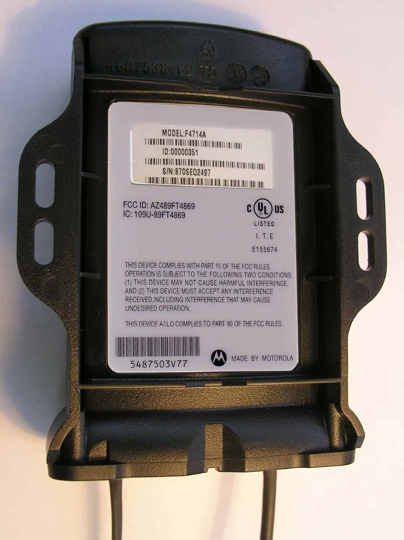
Click to zoom
Application Details
- Equipment Class
- TNB - Licensed Non-Broadcast Station Transmitter
- Date of Grant
- Sep 26, 2004
- Application Purpose
- Original Equipment
- Date of Application
- Sep 26, 2004
- Equipment Note
- Automatic Meter Reader (AMR)
- Frequency Range
- 450.00000000 - 470.00000000
- Company
- Motorola Solutions, Inc.
- Country
- United States
Documents & Files
Document Text
Text extracted from the exhibit documents filed with the FCC. Open a document above to read the original.
Users Manual
a Owner’s Manual Automatic Meter Reader RF Transmitter 6802973C65-A MOTOROLA and the Stylized M Logo are registered in the U.S. Patent and Trademark Office. All other product or service names are the property of their respective owners. Co pyright © 2004 Motorola All Rights Reserved 6802973C65-A @6802973C65@ COMMERCIAL WARRANTY (STANDARD) Motorola radio communications products are warranted to be free from defects in material and workmanship for a period of ONE (1) YEAR, (except for crystals and channel elements which are warranted for a period of ten (10) years), from the date of shipment. Parts, including crystals and channel elements, will be replaced free of charge for the full warranty period but the labor to replace defective parts will only be provided for one Hundred-Twenty (120) days from the date of shipment. Thereafter purchaser must pay for the labor involved in repairing the product or replacing the parts at the prevailing rates together with any transportation charges to or from the place where warranty service is provided. This express warranty is extended by Motorola Communications and Electronics Inc., 1301 E. Algonquin Road, Schaumburg, Illinois 60196, to the original purchaser only, and only to those purchasing for purpose of leasing or solely for commercial, industrial, or governmental use. THIS WARRANTY IS GIVEN IN LIEU OF ALL OTHER WARRANTIES EXPRESS OR IMPLIED WHICH ARE SPECIFICALLY EXCLUDED, INCLUDING WARRANTIES OF MERCHANTABILITY OR FITNESS FOR A PARTICULAR PURPOSE. IN NO EVENT SHALL MOTOROLA BE LIABLE FOR INCIDENTAL OR CONSEQUENTIAL DAMAGES TO THE FULL EXTENT SUCH MAY BE DISCLAIMED BY LAW. In the event of a defect, malfunction or failure to conform to specifications established by seller, or if appropriate, to specifications accepted by Seller in writing, during the period shown, Motorola, at its option, will either repair or replace the product or refund the purchase price thereof, and such action on the part of Motorola shall be the full extent of Motorola’s liability hereunder. This warranty is void if: a. the product is used in other than its normal and customary manner; b. the product has been subject to misuse, accident neglect or damage; c. unauthorized alterations or repairs have been made, or unapproved parts used in the equipment. This warranty extends only to individual products, batteries are excluded, but carry their own separate limited warranty. Because each radio system is unique, Motorola disclaims liability for range, coverage, or operation of the system as a whole under this warranty except by a separate written agreement signed by an officer of Motorola. Non-Motorola manufactured products are excluded from this warranty, but subject to the warranty provided by their manufacturers, a copy of which will be supplied to you on specific written request. In order to obtain performance of this warranty, purchaser must contact its Motorola salesperson or Motorola at the address first above shown, attention Quality Assurance Department. This warranty applies only within the United States. COMPUTER SOFTWARE COPYRIGHTS The Motorola products described in this instruction manual may include copyrighted Motorola computer programs stored in semi conductor memories or other media. Laws in the United States and other countries preserve for Motorola certain exclusive rights for copyrighted computer programs including the exclusive right to copy or reproduce in any form the copyrighted computer program. Accordingly, any copyrighted Motorola computer programs contained in the Motorola products described in this instruction manual may not be copied or reproduced in any manner without the express written permission of Motorola. Furthermore, the purchase of Motorola products shall not be deemed to grant either directly or by implication, estoppel, or otherwise, any license under the copyrights, patents or patent applications of Motorola, except for the normal non-exclusive, royalty free license to use that arises by operation of law in the sale of a product. i CONTENTS INTRODUCTION .......................................................... 1 SCOPE OF THIS MANUAL........................................................ 1 THE AMR SYSTEM - OVERVIEW........................................... 1 GENERAL DESCRIPTION......................................................... 3 INSTALLATION............................................................ 5 GENERAL............................................................................... 5 CHANGING THE TRANSMITTER PARAMETERS....................... 6 ENABLING THE TRANSMITTER............................................... 6 Without the AMR ToolBox ................................................. 6 With the AMR ToolBox ...................................................... 8 RECORDING COUNTER VALUES/READINGS........................... 9 Initial Recording ................................................................ 9 Subsequent Recording during Reprogramming................. 9 DIMENSIONS........................................................................ 11 WALL MOUNTING................................................................ 11 PIT INSTALLATION............................................................... 14 CONNECTIONS...................................................................... 18 Data Connection .............................................................. 18 Programming Connection ............................................... 18 THE AMR RF TRANSMITTER ................................ 19 OVERVIEW........................................................................... 19 COMMUNICATION................................................................ 20 CONNECTORS....................................................................... 20 INTERNAL BATTERY............................................................ 20 Contents ii APPENDIX A: SPECIFICATIONS............................ 23 TRANSMISSION...…
Text truncated - open the document above for the full version.
Attestation Statements
Motorola Inc FCC ID: AZ489FT4869 Motorola Inc., 8000 West Sunrise Blvd., Plantation, FL 33322, USA Page: 2-1 Exhibit 2. Statement of Certification—Pursuant to 47 CFR 2.907 The technical data supplied with this application, having been taken under my supervision is hereby duly certified. The following is a statement of my qualifications: B.Sc in Electrical Engineering, 2001Tel-Aviv University, Israel 4 years experience in HW design. NAME: Uri Shenfeld SIGNATURE : /s/ Uri Shenfeld (signed) DATE: September 19, 2004 POSITION: AMR HW Engineer I hereby certify that the above application was prepared under my direction and that to the best of my knowledge and belief, the facts set forth in the application and accompanying technical data are true and correct. NAME: Ofer Rosenzweig SIGNATURE: /s/ Ofer Rosenzweig (signed) DATE: September 19, 2004 POSITION: HW Development Manager
Cover Letter(s)
FCC ID: AZ489FT4869 ______________________________________________________________________________ 8000 West Sunrise Boulevard, Fort Lauderdale, Florida 33322. Date: 21 st September 2004 Authorization & Evaluation Division Federal Communications Commission Laboratory 7435 Oakland Mills Road Columbia, MD 21046 Subject: Application for Certification of Transmitter with FCC ID: AZ489FT4869. Dear Sir or Madam: Motorola Inc, 8000 West Sunrise Boulevard, Fort Lauderdale, Florida, herein submits application for Certification of the subject transmitter. This transmitter is intended for use an Automatic Meter Reader (AMR) and Data Collection System with capabilities for clear communications with a maximum transmit power of 120 milliWatt operating within the following frequency range of 450 - 470 MHz. Please note that Motorola is submitting this application under FCC Rule Part 90.217, Exempted from Technical Standards due to the output power not exceeding 120mW. The product testing was performed by Hermon Laboratories, which is listed by the FCC under Registration Numbers 90623 and 90624. The subject transmitter complies with Section 90.203 of the Rules in that the operator cannot directly program transmit frequencies using the unit's normally accessible external controls. A complete Certification application is enclosed, contact Mike Ramnath at (954) 723-5793 or Fax (954) 723-4794 if you require any additional information. Sincerely, /s/ Mike Ramnath (signed) Manager, Regulatory Compliance Tel: (954) 723-5793 E-mail: [email protected] EXHIBIT 13a FCC ID: AZ489FT4869 ______________________________________________________________________________ 8000 West Sunrise Boulevard, Fort Lauderdale, Florida 33322. CONFIDENTIALITY REQUESTED Date: 21st September 2004 Authorization & Evaluation Division Federal Communications Commission Laboratory 7435 Oakland Mills Road Columbia, MD 21046 Subject: Confidentiality Request for Transmitter with FCC ID: AZ489FT4869. Dear Sir or Madam: Motorola is requesting that Exhibit 4 (Circuit Descriptions), Exhibit 5 (Schematic Diagrams), Exhibit 10 (Parts List and Tune Up Procedures), and Exhibit 12 (Operational Description) not be made routinely available for public inspection. Motorola considers the information in these exhibits to be classified as trade secrets, pursuant to 47 CFR Section 0.457(d) and Section 552(b)(4) of the Freedom of Information Act. Please mark Exhibits 4, 5, 10, and 12 as “Confidential.” Please contact me if you require any additional information. Sincerely, /s/ Mike Ramnath (signed) Manager, Regulatory Compliance Tel: (954) 723-5793 E-mail: [email protected] EXHIBIT 13b
External Photos
Motorola Inc. FCC ID: AZ489FT4869 Exhibit 3 Page 1 of 4 Exhibit 3 –External Photographs EXTERNAL PHOTOGRAPHS This document contains 3 photographs Motorola Inc. FCC ID: AZ489FT4869 Exhibit 3 Page 2 of 4 Photograph No.1 AMR transmitter front view Motorola Inc. FCC ID: AZ489FT4869 Exhibit 3 Page 3 of 4 Photograph No.2 AMR transmitter rear side view Motorola Inc. FCC ID: AZ489FT4869 Exhibit 3 Page 4 of 4 Photograph No.3 AMR transmitter antenna assembly
ID Label/Location Info
Motorola Inc FCC ID: AZ489FT4869 Exhibit 1 Page: 3 Exhibit 1. FCC Identification Label -- Pursuant to 47 CFR 2.1033(c)(11) 1.1. Location Back side of the Automatic Meter Reader case. 1.2. Markings (Text) Enlarged view of label (showing FCC ID and manufacturer type number): Motorola Inc FCC ID: AZ489FT4869 Exhibit 1 Page: 3 Label location Motorola Inc FCC ID: AZ489FT4869 Exhibit 1 Page: 3 Exhibit 1A. General Information 1A.1. Production Plans Quantity production is planned. 1A.2. Application References -- Pursuant to 47 CFR 2.948 and 2.1061 Reference is made to the following Motorola "Application References" Hermon Labs, located in Binyamina Israel is listed with FCC and Industry Canada as follows: 1. FCC OATS registration number is: 90623 2. FCC Anechoic chamber registration number is: 90624 3. Industry Canada OATS registration number is: IC 2186-1 4. Industry Canada anechoic chamber registration number is: IC 2186-2 5. Accredited by A2LA. 1A.3. Data Submittal Procedure Data located in Exhibit 6 is supplied in accordance with Part 2, Sub-part J and Part 90, Sub-part I of the Commission’s rules.
Internal Photos
Motorola Inc FCC ID: AZ489FT4869 Exhibit 9 Page 1 of 5 INTERNAL PHOTOGRAPHS This document contains 4 photographs Motorola Inc FCC ID: AZ489FT4869 Exhibit 9 Page 2 of 5 Photograph No.1 AMR transmitter internal view Motorola Inc FCC ID: AZ489FT4869 Exhibit 9 Page 3 of 5 Photograph No.2 AMR transmitter PCB component side Motorola Inc FCC ID: AZ489FT4869 Exhibit 9 Page 4 of 5 Photograph No.3 AMR transmitter PCB with shields removed Motorola Inc FCC ID: AZ489FT4869 Exhibit 9 Page 5 of 5 Photograph No.4 AMR transmitter PCB second side
RF Exposure Info
Certificate No. 1449-01 Form Regulatory Compliance Summary Rpt 2 Rev 1.0 1of 3 CGISS EME Laboratory 8000 West Sunrise Blvd. Fort Lauderdale, FL. 33322 S.A.R. EME Test Report Note: Consistent with the ISO/IEC 17025 recommendation this report shall not be reproduced in part without written approval from an officially designated representative of the Motorola EME Laboratory. Based on the information and the testing results provided herein, the undersigned certifies that when used as stated in the operating instructions supplied, said product complies with all applicable national and international reference standards and guidelines. Signature on file – Deanna Zakharia for Ken Enger 9/21/2004 ___________________________________________________________ _________________________ Ken Enger Date Approved Senior Resource Manager, Product Safety and EME Director, Phone: 954-723-6299 Date of Report: 9/21/04 Report ID: FCC rpt_AZ489FT4869-AMR_DIOS_Rev O_040921_SR582 Report Author: Michael Sailsman (Global EME Regulatory Affairs Liaison) Resp. Engineer: Deanna Zakharia (Elect. Principal Staff Eng.) Tested By: NA Date submitted: 8/16/04 Date/s Tested: NA Manufacturer: Motorola Sector/Group/Div.: Motorola South - ARAD DUT Description: Transmitter one pulse meter UHF, 100mW, 12.5KHz Test TX mode(s): NA FCC ID(s): AZ489FT4869 Trade Name/Model(s): F4714A Classification: General Population/Uncontrolled Exposure Category IEEE 1-g and 10-g Max. Power output: 120mW TX Frequency Bands: 450-470MHz Test Frequency/s: NA Model(s) Tested: NA Model(s) Certified: F4714A Serial Number(s): NA Certificate No. 1449-01 Form Regulatory Compliance Summary Rpt 2 Rev 1.0 2of 3 This device is designed to comply with the following national and international standards and guidelines. • United States Federal Communications Commission, Code of Federal Regulations; 47CFR part 2 sub-part J • IEEE 1528, 2003 "Recommended Practice for Determining the Peak Spatial-Average Specific Absorption Rate (SAR) in the Human Head from Wireless Communications Devices: Measurement Techniques," • American National Standards Institute (ANSI) / Institute of Electrical and Electronic Engineers (IEEE) C95. 1-1992 • Institute of Electrical and Electronic Engineers (IEEE) C95.1-1999 Edition • International Commission on Non-Ionizing Radiation Protection (ICNIRP) 1998 • Ministry of Health (Canada) Safety Code 6. Limits of Human Exposure to Terminal frequency Electromagnetic Fields in the Frequency Range from 3 kHz to 300 GHz, 1999 • Australian Communications Authority Terminal communications (Electromagnetic Radiation - Human Exposure) Standard 2003 • ANATEL, Brazil Regulatory Authority, Resolution No. 303 of July 2, 2002 "Regulation of the limitation of exposure to electrical, magnetic, and electromagnetic fields in the radio frequency range between 9KHz and 300 GHz." and “Attachment to resolution # 303 from July 2, 2002” This report presents product description and non test MPE compliance justification for the device stated herein. Product Description: FCC ID: AZ489FT4869 model F4714A is an automatic meter reader (AMR) transmitter operating in the 450- 470MHz band. This device incorporates frequency modulated DPSK signaling with 12.5KHz channel separation. The device utilizes a logic circuit interface that is used to trigger a single pulse-type meter. The maximum transmission duty cycle of this device is based on a one second pulse transmitted once every 4 hours (0.06% - 30 minute time averaged). The nominal power of this device is 100mW with a maximum output power of 120mW. This device uses a fixed external ½ wave wire antenna and is powered by a 3.6V Lithium Ion battery. The intended use is mounted on a wall or installed in a pit per the user manual instructions. While this product will be marketed to and used by employees solely for work related operations such as public agencies and utilities, it also meets the General Population/Uncontrolled limits. User training is the responsibility of these agencies, who can be expected to employ the usage instructions, safety information and operational cautions set forth in the user's manual, instructional sessions or other means. Motorola also makes available to its customers training classes on the proper use of two-way radios and wireless data devices. Certificate No. 1449-01 Form Regulatory Compliance Summary Rpt 2 Rev 1.0 3of 3 Offered accessories Antenna Model Description 1587508V79 450-470MHz ½ wave antenna; 10cm; 0dBd FHN6584A Pit antenna kit Justification for test exclusion: The following conservative power density free-space formula, as referenced in OET Bulletin 65, Edition 97-01, 1997, was used to determine if the potential power density of this product could exceed the MPE limits for the general population/uncontrolled exposure classification. S is the power density at d distance away from an antenna with an output power of Pt and gain of Gt. To provide a conservative estimate of the power density the factor F should be set to 4 to account for the superposition of a reflected and a line-of-sight wave. This would result in twice the E field, or four times the power density. This is a conservative approach, since it assumes perfect reflection and no added path loss of the reflected signal. This formula is applicable if the user is in the far-field, and it gives a conservative over estimation if the person is in the near field. Using this equation with F = 4 offers "a truly worst-case prediction of power density". The example presented below applies the worst case parameters for this device to the above formula and demonstrates compliance to the applicable standard. Input variables: Maximum Power output = 0.120 Duty Cycle (30 minutes time averaged limit) = 0.06% Lowest Frequency = 450MHz Antenna gain = 0dBd Distance (cm) = 20 Result = 8.7E-05 mW/cm^2 Conclusion: The maximum permissible exposure for uncontrolled environments is 0.30 mW/cm^2 and 1.5 mW/cm^2 for controlled environments. Based on time ave…
Text truncated - open the document above for the full version.
Test Report
Hermon Laboratories Ltd. P.O.Box 23, Binyamina 30500, Israel Tel. +972 4628 8001 Fax. +972 4628 8277 E-mail: [email protected] Page 1 of 79 Report ID: MOTRAD_FCC.16016_rev1.doc Date of Issue: 8/23/2004 Electrical TEST REPORT ACCORDING TO: FCC CFR 47 PART 90 SUBPART I and PART 15 SUBPART B FOR: Motorola Communication Israel Ltd. Automatic Meter Reader Model: AMR This report is in conformity with ISO/ IEC 17025. The A2LA logo endorsement applies only to the test methods and the standards that are listed in the scope of Hermon Laboratories accreditation. The test results relate only to the items tested. This test report shall not be reproduced in any form except in full with the written approval of Hermon Laboratories Ltd. Report ID: MOTRAD_FCC.16016_rev1.doc Date of Issue: 8/23/2004 Project: 16016, Motorola Communication Israel Ltd., Automatic Meter Reader Page 2 of 79 Table of contents 1 Applicant information..................................................................................................................................................... 3 2 Equipment under test attributes .................................................................................................................................... 3 3 Manufacturer information .............................................................................................................................................. 3 4 Test details.................................................................................................................................................................... 3 5 Tests summary.............................................................................................................................................................. 4 6 EUT description............................................................................................................................................................. 5 6.1 General information....................................................................................................................................................... 5 6.2 Ports and lines .............................................................................................................................................................. 5 6.3 Operating frequencies ................................................................................................................................................... 5 6.4 Changes made in the EUT ............................................................................................................................................ 5 6.5 Test configuration.......................................................................................................................................................... 5 6.6 Transmitter characteristics ............................................................................................................................................ 6 7 Transmitter tests according to 47CFR part 90 subpart I requirements .......................................................................... 7 7.1 Effective radiated power of carrier................................................................................................................................. 7 7.2 Occupied bandwidth test ............................................................................................................................................. 14 7.3 Frequency stability test................................................................................................................................................ 18 7.4 Transient frequency behaviour test ............................................................................................................................. 20 7.5 Band edge emission.................................................................................................................................................... 26 7.6 Radiated spurious emission measurements................................................................................................................ 31 7.7 RF exposure..................................................................................................................Error! Bookmark not defined. 7.8 Radiated emission measurements .............................................................................................................................. 47 8 APPENDIX A Test equipment and ancillaries used for tests....................................................................................... 47 9 APPENDIX B Measurement uncertainties................................................................................................................... 47 10 APPENDIX C Test facility description ......................................................................................................................... 47 11 APPENDIX D Specification references ....................................................................................................................... 47 12 APPENDIX E Abbreviations and acronyms................................................................................................................. 47 13 APPENDIX F Test equipment correction factors ......................................................................................................... 47 Report ID: MOTRAD_FCC.16016_rev1.doc Date of Issue: 8/23/2004 Project: 16016, Motorola Communication Israel Ltd., Automatic Meter Reader Page 3 of 79 1 Applicant information Client name: Motorola Communication Israel Ltd. Address: 3 Kremenetski street, P.O.B. 25016, 67899 Tel Aviv, Israel Telephone: +972 3565 8888 Fax: +972 3565 8888 E-mail: [email protected] Contact name: Mr. Uri Shenfeld 2 Equipment under test attributes Product name: Automatic Meter Reader Model(s): AMR Serial number: WUB00091 Receipt date 7/25/2004 10:13:00 AM 3 Manufac…
Text truncated - open the document above for the full version.
Test Setup Photos
Motorola Inc. FCC ID: AZ489FT4869 Exhibit 7 Page 1 of 8 Exhibit 7- SETUP PHOTOGRAPHS SETUP PHOTOGRAPHS This document contains 7 photographs Motorola Inc. FCC ID: AZ489FT4869 Exhibit 7 Page 2 of 8 Photograph No.1 Spurious emissions measurement setup in the anechoic chamber with loop antenna Motorola Inc. FCC ID: AZ489FT4869 Exhibit 7 Page 3 of 8 Photograph No.2 Radiated emissions measurement setup in the anechoic chamber with biconilog antenna Motorola Inc. FCC ID: AZ489FT4869 Exhibit 7 Page 4 of 8 Photograph No.3 AMR configuration for radiated emissions measurements Motorola Inc. FCC ID: AZ489FT4869 Exhibit 7 Page 5 of 8 Photograph No.4 Setup for substitution ERP measurements Motorola Inc. FCC ID: AZ489FT4869 Exhibit 7 Page 6 of 8 Photograph No.5 Frequency stability test setup Motorola Inc. FCC ID: AZ489FT4869 Exhibit 7 Page 7 of 8 Photograph No.6 Transient frequency behaviour test setup Motorola Inc. FCC ID: AZ489FT4869 Exhibit 7 Page 8 of 8 Photograph No.7 Maximum permissible exposure (MPE) measurement set up
Contact Information
Applicant
Arine Lee(Certification Manager)
Test Firm
MotorolaWilliam Elliott
Technical Specifications
| # | Rule Parts | Frequency Range | Power Output | Emission | Tolerance |
|---|---|---|---|---|---|
| 1 | 90 | 450 MHz - 470 MHz | 120.00 mW | 7K70G1D | 1.5000000000 ppm |
Other Applications from Motorola Solutions, Inc.

AZ489FT4980
Sep 08, 2026Portable two way radio
Equipment Class
TNF - Licensed Non-Broadcast Transmitter Held to FaceAZ489FT4981
Aug 14, 2026Handheld Portable - TANAPA BPR 45 400-470 MHZ 4W NKP
Equipment Class
TNF - Licensed Non-Broadcast Transmitter Held to Face
AZ489FT7187
Jul 13, 2026Portable 2-Way Radio with Bluetooth, Bluetooth LE, WIFI 2.4GHz, WIFI 5GHz, LTE
Equipment Class
DSS - Part 15 Spread Spectrum TransmitterAZ499FT6031
May 11, 2026Operation Critical Wireless Earpiece PTT
Equipment Class
DSS - Part 15 Spread Spectrum Transmitter
AZ499FT5879
Dec 19, 20252-way Portable Radio with BT, BTLE, WIFI, NFC and LTE
Equipment Class
DSS - Part 15 Spread Spectrum Transmitter