AZ489FT4871Distributed I/O System
Motorola Solutions, Inc.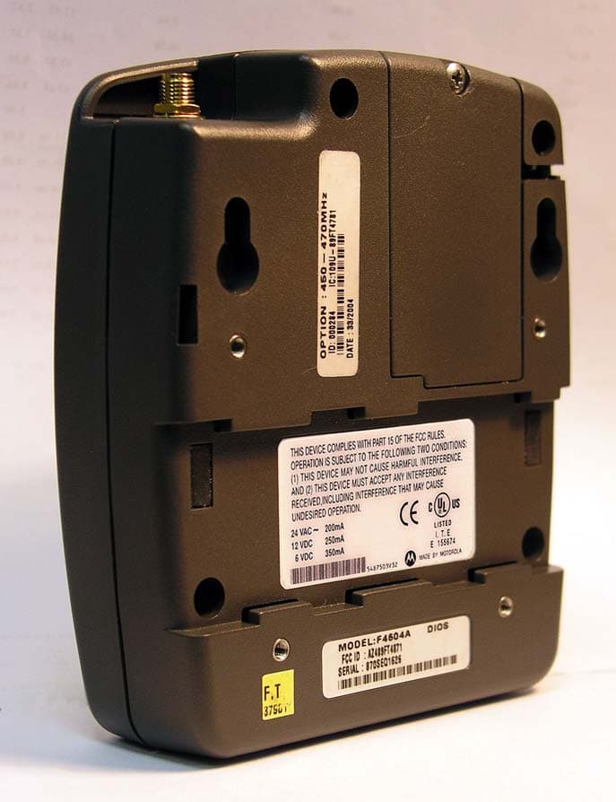
Click to zoom
Application Details
- Equipment Class
- TNT - Licensed Non-Broadcast Transmitter Worn on Body
- Date of Grant
- Oct 28, 2004
- Application Purpose
- Original Equipment
- Date of Application
- Oct 28, 2004
- Equipment Note
- Distributed I/O System
- Frequency Range
- 450.00000000 - 470.00000000
- Company
- Motorola Solutions, Inc.
- Country
- United States
Documents & Files
Document Text
Text extracted from the exhibit documents filed with the FCC. Open a document above to read the original.
Users Manual
Owner’s Manual Distributed I/O System- Piccolo Interface Unit (PIU) and Piccolo-XR Unit 6802974C40-O 6802974C40-O 6802974C40 MOTOROLA and the Stylized M Logo are registered in the U.S. Patent and Trademark Office. All other product or service names are the property of their respective owners. Copyright © 2004 Motorola All Rights Reserved COMMERCIAL WARRANTY (STANDARD) Motorola radio communications products are warranted to be free from defects in material and workmanship for a period of ONE (1) YEAR, (except for crystals and channel elements which are warranted for a period of ten (10) years), from the date of shipment. Parts, including crystals and channel elements, will be replaced free of charge for the full warranty period but the labor to replace defective parts will only be provided for one Hundred-Twenty (120) days from the date of shipment. Thereafter purchaser must pay for the labor involved in repairing the product or replacing the parts at the prevailing rates together with any transportation charges to or from the place where warranty service is provided. This express warranty is extended by Motorola Communications and Electronics Inc., 1301 E. Algonquin Road, Schaumburg, Illinois 60196, to the original purchaser only, and only to those purchasing for purpose of leasing or solely for commercial, industrial, or governmental use. THIS WARRANTY IS GIVEN IN LIEU OF ALL OTHER WARRANTIES EXPRESS OR IMPLIED WHICH ARE SPECIFICALLY EXCLUDED, INCLUDING WARRANTIES OF MERCHANTABILITY OR FITNESS FOR A PARTICULAR PURPOSE. IN NO EVENT SHALL MOTOROLA BE LIABLE FOR INCIDENTAL OR CONSEQUENTIAL DAMAGES TO THE FULL EXTENT SUCH MAY BE DISCLAIMED BY LAW. In the event of a defect, malfunction or failure to conform to specifications established by seller, or if appropriate, to specifications accepted by Seller in writing, during the period shown, Motorola, at its option, will either repair or replace the product or refund the purchase price thereof, and such action on the part of Motorola shall be the full extent of Motorola’s liability hereunder. This warranty is void if: a. the product is used in other than its normal and customary manner; b. the product has been subject to misuse, accident neglect or damage; c. unauthorized alterations or repairs have been made, or unapproved parts used in the equipment. This warranty extends only to individual products, batteries are excluded, but carry their own separate limited warranty. Because each radio system is unique, Motorola disclaims liability for range, coverage, or operation of the system as a whole under this warranty except by a separate written agreement signed by an officer of Motorola. Non-Motorola manufactured products are excluded from this warranty, but subject to the warranty provided by their manufacturers, a copy of which will be supplied to you on specific written request. In order to obtain performance of this warranty, purchaser must contact its Motorola salesperson or Motorola at the address first above shown, attention Quality Assurance Department. This warranty applies only within the United States. COMPUTER SOFTWARE COPYRIGHTS The Motorola products described in this instruction manual may include copyrighted Motorola computer programs stored in semi conductor memories or other media. Laws in the United States and other countries preserve for Motorola certain exclusive rights for copyrighted computer programs including the exclusive right to copy or reproduce in any form the copyrighted computer program. Accordingly, any copyrighted Motorola computer programs contained in the Motorola products described in this instruction manual may not be copied or reproduced in any manner without the express written permission of Motorola. Furthermore, the purchase of Motorola products shall not be deemed to grant either directly or by implication, estoppel, or otherwise, any license under the copyrights, patents or patent applications of Motorola, except for the normal non-exclusive, royalty free license to use that arises by operation of law in the sale of a product. Introduction CONTENTS INTRODUCTION..............................................................................1 Scope of this Manual....................................................................1 General Description......................................................................1 Safety Handling Instructions.......................................................5 INSTALLATION...............................................................................7 General..........................................................................................7 PIU Installation.............................................................................8 Mounting the PIU On A Wall Using Screws..............................9 Mounting the PIU Using a Bracket...........................................10 PIU DIN Rail Mounting.............................................................11 PIU Electrical Connections........................................................12 PIU Antenna Connection...........................................................18 Piccolo–XR Installation.............................................................19 Piccolo–XR Screw Mounting Options......................................20 Piccolo–XR Electrical Connections...........................................22 THE DIOS PIU AND PICCOLO-XR UNITS....................................27 PIU Overview..............................................................................27 PIU Communication Ports.........................................................28 PIU Connectors...........................................................................29 PIU LED Operation...................................................................29 PIU Adapter Operation.............................................................30 PIU Portable Use........................................................................30 P…
Text truncated - open the document above for the full version.
Users Manual
English Product Safety and RF Energy Exposure Booklet for Piccolo Interface Units The Piccolo Interface Unit (PIU) and Piccolo-XR unit are portable devices which are most commonly used in fixed installations. BEFORE USING THIS PIU, READ THIS BOOKLET WHICH CONTAINS IMPORTANT OPERATING INSTRUCTIONS FOR SAFE USAGE AND RF ENERGY AWARENESS AND CONTROL INFORMATION AND OPERATIONAL INSTRUCTIONS FOR COMPLIANCE WITH RF ENERGY EXPOSURE LIMITS IN APPLICABLE NATIONAL AND INTERNATIONAL STANDARDS. ALSO READ THE OPERATIONAL INSTRUCTIONS FOR SAFE USAGE. ! C a u t i o n Copyright © Motorola 2004 All Rights Reserved 6802974C70 6802974C70-O DIOS_SafetyBooklet-Portable_Eng.fm Page 1 Tuesday, October 12, 2004 12:59 PM 2 English RF Energy Exposure Awareness and Control Information and Operational Instructions NOTICE: The PIU and Piccolo-XR devices are authorized for general population consumer use. The PIU and Piccolo-XR use electromagnetic energy in the radio frequency (RF) spectrum to provide communications between two or more users over a distance. They use radio frequency (RF) energy or radio waves to send and receive data. RF energy is one form of electromagnetic energy. Other forms include, but are not limited to, sunlight and x-rays. RF energy, however, should not be confused with these other forms of electromagnetic energy, which when used improperly, can cause biological damage. Very high levels of x-rays, for example, can damage tissues and genetic material. Experts in science, engineering, medicine, health, and industry work with organizations to develop standards for safe exposure to RF energy. These standards provide recommended levels of RF exposure for both workers and the general public. These recommended RF exposure levels include substantial margins of protection. All Motorola PIUs and Piccolo-XR units are designed, manufactured, and tested to ensure they meet government-established RF exposure levels. In addition, manufacturers also recommend specific operating instructions to users of PIUs and Piccolo-XR units. These instructions are important because they inform users about RF energy exposure and provide simple procedures on how to control it. DIOS_SafetyBooklet-Portable_Eng.fm Page 2 Tuesday, October 12, 2004 12:59 PM 3 English Please refer to the following websites for more information on what RF energy exposure is and how to control your exposure to assure compliance with established RF exposure limits: http://www.fcc.gov/oet/rfsafety/rf-faqs.html http://www.osha.gov/SLTC/radiofrequencyradiation/index.html Federal Communication Commission (FCC) Regulations The FCC rules require manufacturers to comply with the FCC RF energy exposure limits for portable PIUs and Piccolo-XR units before they can be marketed in the U.S. Compliance with RF Exposure Standards Your Motorola PIU and Piccolo-XR are designed and tested to comply with a number of national and International standards and guidelines (listed below) for human exposure to radio frequency electromagnetic energy. The PIU and Piccolo-XR comply with the IEEE (FCC) and ICNIRP exposure limits for uncontrolled RF exposure environments. In terms of measuring RF energy for compliance with these exposure guidelines, your PIU and Piccolo-XR generate measurable RF energy only while they are transmitting, not when they are receiving or in standby mode. DIOS_SafetyBooklet-Portable_Eng.fm Page 3 Tuesday, October 12, 2004 12:59 PM 4 English Your Motorola PIU and Piccolo-XR comply with the following RF energy exposure standards and guidelines: • United States Federal Communications Commission, Code of Federal Regulations; 47CFR part 2 sub-part J • American National Standards Institute (ANSI) / Institute of Electrical and Electronic Engineers (IEEE) C95. 1-1992 • Institute of Electrical and Electronic Engineers (IEEE) C95.1-1999 Edition • International Commission on Non-Ionizing Radiation Protection (ICNIRP) 1998 • Ministry of Health (Canada) Safety Code 6. Limits of Human Exposure to Radiofrequency Electromagnetic Fields in the Frequency Range from 3 kHz to 300 GHz, 1999 • Australian Communications Authority Radiocommunications (Electromagnetic Radiation – Human Exposure) Standard, 2003 • ANATEL ANNEX to Resolution No. 303 of July 2, 2002 "Regulation of limitation of exposure to electrical, magnetic and electromagnetic fields in the radio frequency range between 9 KHz and 300 GHz" and "Attachment to resolution # 303 from July 2, 2002" RF Exposure Compliance and Control Guidelines and Operating Instructions To control your exposure and ensure compliance with the uncontrolled environment exposure limits, always adhere to the following procedures. Guidelines: • Do not remove the RF Exposure Label from the device. • User awareness instructions should accompany device when transferred to other users. • Do not use this device if the operational requirements described herein are not met. DIOS_SafetyBooklet-Portable_Eng.fm Page 4 Tuesday, October 12, 2004 12:59 PM 5 English Operating Instructions • When worn on the body, always place the PIU in a Motorola-approved clip, holder, holster, case, or body harness for this product. Using approved body- worn accessories is important because the use of non-Motorola-approved accessories may result in exposure levels, which exceed the FCC occupational/controlled environment RF exposure limits. • If you are not using a body-worn accessory and are not using the PIU/Piccolo- XR in the intended-use position, ensure that the antenna and the unit are kept at least one inch (2.5 centimeters) from the body when transmitting. Keeping the PIU and the Piccolo-XR at a proper distance is important because RF exposures decrease with increasing distance from the antenna. Approved Accessories • Use only Motorola-approved supplied or replacement antennas, batteries, and accessories. Use of Non-Motorola approved antennas, batteries, and accessories may exceed the FCC (IEEE) and ICNIRP RF exposure guidelines. Additional Information For a…
Text truncated - open the document above for the full version.
Attestation Statements
Motorola Inc. FCC ID: AZ489FT4871 Page: 1 -1 Exhibit 2. Statement of Certification—Pursuant to 47 CFR 2.907 The technical data supplied with this application, having been taken under my supervision is hereby duly certified. The following is a statement of my qualifications: B.Sc in Electrical Engineering, 1998 Technology Institute, Israel 10 years experience in HW design. NAME: Tomer Azov SIGNATURE: /s/ Tomer Azov (signed) DATE: 19 th September 2004 POSITION: Distributed I/O HW Project Manager I hereby certify that the above application was prepared under my direction and that to the best of my knowledge and belief, the facts set forth in the application and accompanying technical data are true and correct. NAME: Ofer Rosenzweig SIGNATURE: /s/ Ofer Rosenzweig (signed) DATE: 19 th September 2004 POSITION: HW Development Manager
Cover Letter(s)
FCC ID: AZ489FT4871 ______________________________________________________________________________ 8000 West Sunrise Boulevard, Fort Lauderdale, Florida 33322. USA Date: 27 th October 2004 Authorization & Evaluation Division Federal Communications Commission Laboratory 7435 Oakland Mills Road Columbia, MD 21046 Subject: Application for Certification of Transmitter with FCC ID: AZ489FT4871. Piccolo Interface Unit (PIU) and Piccolo-XR of the distributed I/O system. Dear Sir or Madam: Motorola Inc, 8000 West Sunrise Boulevard, Fort Lauderdale, Florida, herein submits application for Certification of the subject transmitter. Please find the attached application for Certification of the Piccolo Interface Unit (PIU) and the Piccolo-XR units of the distributed I/O system, operating with a maximum transmit power of 120 milliWatts at the frequency range of 450 - 470 MHz. Please note that Motorola is submitting this application under FCC Rule Part 90.217, Exempted from Technical Standards due to the output power not exceeding 120mW. The product testing was performed by Hermon Laboratories, which is listed by the FCC under Registration Numbers 90623 and 90624. The subject transmitter complies with Section 90.203 of the Rules in that the operator cannot directly program transmit frequencies using the unit's normally accessible external controls. A complete Certification application is enclosed, contact Mike Ramnath at (954) 723-5793 or Fax (954) 723-4794 if you require any additional information. Sincerely, /s/ Mike Ramnath (signed) Manager, Regulatory Compliance Tel: (954) 723-5793 E-mail: [email protected] EXHIBIT 13a
Cover Letter(s)
FCC ID: AZ489FT4871 ______________________________________________________________________________ 8000 West Sunrise Boulevard, Fort Lauderdale, Florida 33322. USA CONFIDENTIALITY REQUESTED Date: 27 th October 2004 Authorization & Evaluation Division Federal Communications Commission Laboratory 7435 Oakland Mills Road Columbia, MD 21046 Subject: Confidentiality Request for Transmitter with FCC ID: AZ489FT4871. Dear Sir or Madam: Motorola is requesting that Exhibit 4 (Circuit Descriptions), Exhibit 5 (Schematic Diagrams), Exhibit 10 (Parts List and Tune-Up Procedures), and Exhibit 12 (Operational Description) not be made routinely available for public inspection. Motorola considers the information in these exhibits to be classified as trade secrets, pursuant to 47 CFR Section 0.457(d) and Section 552(b)(4) of the Freedom of Information Act. Please mark Exhibits 4, 5, 10, and 12 as “Confidential.” Please contact me if you require any additional information. Sincerely, /s/ Mike Ramnath (signed) Manager, Regulatory Compliance Tel: (954) 723-5793 E-mail: [email protected] EXHIBIT 13b
External Photos
Motorola Inc. FCC ID: AZ489FT4871 Exhibit 3 Page 1 of 5 Exhibit 3 –External Photographs EXTERNAL PHOTOGRAPHS This document contains 5 photographs Motorola Inc. FCC ID: AZ489FT4871 Exhibit 3 Page 2 of 5 Photograph No.1 PIU front view Motorola Inc. FCC ID: AZ489FT4871 Exhibit 3 Page 3 of 5 Photograph No.2 PIU rear side view Motorola Inc. FCC ID: AZ489FT4871 Exhibit 3 Page 4 of 5 Photograph No.3 PIU bottom view (connectors side) Photograph No.4 Piccolo-XR front view Motorola Inc. FCC ID: AZ489FT4871 Exhibit 3 Page 5 of 5 Photograph No.5 Piccolo-XR rear side view
ID Label/Location Info
Motorola Inc FCC ID: AZ489FT4871 Exhibit 1 Page: 1- 1 Exhibit 1. FCC Identification Label -- Pursuant to 47 CFR 2.1033(c)(11) 1.1. Location Back side of the Piccolo Interface Unit and Piccolo-XR housing. 1.2. Markings (Text) Enlarged view of label (showing FCC ID and manufacturer type number): Motorola Inc FCC ID: AZ489FT4871 Exhibit 1 Page: 1- 2 Label location Motorola Inc FCC ID: AZ489FT4871 Exhibit 1 Page: 1- 3 Exhibit 1A. General Information 1A.1. Production Plans Quantity production is planned. 1A.2. Application References -- Pursuant to 47 CFR 2.948 and 2.1061 Reference is made to the following Motorola "Application References" Hermon Labs, located in Binyamina Israel is listed with FCC and Industry Canada as follows: 1. FCC OATS registration number is: 90623 2. FCC Anechoic chamber registration number is: 90624 3. Industry Canada OATS registration number is: IC 2186-1 4. Industry Canada anechoic chamber registration number is: IC 2186-2 5. Accredited by A2LA. 1A.3. Data Submittal Procedure Data located in Exhibit 6 is supplied in accordance with Part 2, Sub-part J and Part 90, Sub-part I of the Commission’s rules.
Internal Photos
Motorola Inc. FCC ID: AZ489FT4871 Exhibit 9 Page 1 of 9 INTERNAL PHOTOGRAPHS This document contains 8 photographs Motorola Inc. FCC ID: AZ489FT4871 Exhibit 9 Page 2 of 9 Photograph No.1 Piccolo Interface Unit (PIU) internal view Motorola Inc. FCC ID: AZ489FT4871 Exhibit 9 Page 3 of 9 Photograph No.2 Piccolo Interface Unit (PIU) internal view Motorola Inc. FCC ID: AZ489FT4871 Exhibit 9 Page 4 of 9 Photograph No.3 Piccolo Interface Unit (PIU), PCB bottom side view Motorola Inc. FCC ID: AZ489FT4871 Exhibit 9 Page 5 of 9 Photograph No.4 PIU internal view, second side Motorola Inc. FCC ID: AZ489FT4871 Exhibit 9 Page 6 of 9 Photograph No.5 PIU internal view, PCB top side Motorola Inc. FCC ID: AZ489FT4871 Exhibit 9 Page 7 of 9 Photograph No.6 PCB with RF module removed Motorola Inc. FCC ID: AZ489FT4871 Exhibit 9 Page 8 of 9 Photograph No.7 RF module view, first side Motorola Inc. FCC ID: AZ489FT4871 Exhibit 9 Page 9 of 9 Photograph No.8 RF module view, second side
RF Exposure Info
Certificate Number: 1449-01 CGISS EME Form-SAR-Rpt-Rev. 3.00 Page 1 of 20 CGISS EME Test Laboratory 8000 West Sunrise Blvd Fort Lauderdale, FL. 33322 S.A.R. EME Compliance Test Report Part 1 of 2 Note: This report shall not be reproduced without written approval from an officially designated representative of the Motorola EME Laboratory. Based on the information and the testing results provided herein, the undersigned certifies that when used as stated in the operating instructions supplied, said product complies with the national and international reference standards and guidelines listed in section 2.0 of this report. Signature on file 10/27/04 ____________________________________________________________ _________________________ Ken Enger Date Approved Senior Resource Manager, Laboratory Director, CGISS EME Lab Date of Report: October 26, 2004 Report Revision: Rev. O Manufacturer: Motorola Product Description: Distributed Input Output System (DIOS); 100mW UHF 450- 470MHz 12.5KHz FCC ID: AZ489FT4871 Device Model: F4614A (Piccolo XR), F4604A (PIU Controller) Test Period: 9/17/04-10/22/04 Technician: Ed Church (EME Technician Electronics II) Responsible Eng: Deanna Zakharia (Elect. Principle Staff Eng.) Author: Michael Sailsman (Global EME Regulatory Affairs Liaison) Certificate Number: 1449-01 CGISS EME Form-SAR-Rpt-Rev. 3.00 Page 2 of 20 TABLE OF CONTENTS Part 1 of 2 1.0 Introduction 2.0 Reference Standards and Guidelines 3.0 Description of Test Sample 3.1 Test Signal 3.2 Test Output Power 4.0 Description of Test Equipment 4.1 Description of S.A.R Measurement System 4.2 Description of Phantom 4.2.1 Flat Phantom 4.2.2 SAM phantom 4.3 Simulated Tissue Properties 4.3.1 Type of Simulated Tissue 4.3.2 Simulated Tissue Composition 4.4 Test conditions 5.0 Probe Scan Procedures 5.1 Shortened scan rationale 5.2 Description of Test Procedure 5.3 Device Test Positions 5.3.1 Body 5.3.2 Head 5.3.3 Face 5.4 Test Position Photographs 6.0 Measurement Uncertainty 7.0 S.A.R. Test Results 7.1 S.A.R. results 7.2 Peak S.A.R. location 7.3 Highest S.A.R. results calculation methodology 8.0 Conclusion Part 2 of 2 Appendix A: Power Slump Data/Shortened scan Appendix B: Data Results Appendix C: Dipole System Performance Check Results Appendix D: Probe/Dipole Calibration Certificates Appendix E: Illustration of Body-worn Accessories Appendix F: Accessories and options test status and separation distances Certificate Number: 1449-01 CGISS EME Form-SAR-Rpt-Rev. 3.00 Page 3 of 20 REVISION HISTORY Date Revision Comments 10/26/04 O Release of pilot results Certificate Number: 1449-01 CGISS EME Form-SAR-Rpt-Rev. 3.00 Page 4 of 20 1.0 Introduction This report details the utilization, test setup, test equipment, and test results of the Specific Absorption Rate (S.A.R.) measurements performed at the CGISS EME Test Lab for model number F4614A (Piccolo XR), F4604A (Piccolo Interface unit – PIU Controller), FCC ID: AZ489FT4871. The applicable exposure environment is General Population/Uncontrolled. 2.0 Reference Standards and Guidelines This product is designed to comply with the following national and international standards and guidelines. • United States Federal Communications Commission, Code of Federal Regulations; 47CFR part 2 sub-part J • IEEE 1528, 2003 "Recommended Practice for Determining the Peak Spatial-Average Specific Absorption Rate (SAR) in the Human Head from Wireless Communications Devices: Measurement Techniques" • American National Standards Institute (ANSI) / Institute of Electrical and Electronic Engi- neers (IEEE) C95. 1-1992 • Institute of Electrical and Electronic Engineers (IEEE) C95.1-1999 Edition • International Commission on Non-Ionizing Radiation Protection (ICNIRP) 1998 • Ministry of Health (Canada) Safety Code 6. Limits of Human Exposure to Terminal frequency Electromagnetic Fields in the Frequency Range from 3 kHz to 300 GHz, 1999 • Australian Communications Authority Radiocommunications (Electromagnetic Radiation - Human Exposure) Standard 2003 • ANATEL, Brazil Regulatory Authority, Resolution No. 303 of July 2, 2002 "Regulation of the limitation of exposure to electrical, magnetic, and electromagnetic fields in the radio frequency range between 9KHz and 300 GHz." and “Attachment to resolution # 303 from July 2, 2002” Certificate Number: 1449-01 CGISS EME Form-SAR-Rpt-Rev. 3.00 Page 5 of 20 3.0 Description of Test Sample Piccolo XLR PIU FCC ID: AZ489FT4871 is a self-sustained distributed I/O system (DIOS) that operates as part of a monitor and control system such as the IRRInet field unit irrigation control system. The DIOS consists of an IRRInet Field unit, the Piccolo Interface unit, and the Piccolo XR unit. The PIU connects to the IRRInet via RS232 or RS485 and uses RF communications to link to the Piccolo XR units that are typically mounted in the field. The DIOS automatically builds communications network utilizing the Store and Forward (S&F) technology enabling larger coverage than is possible with a single radio communicating with the PIU. Up to 256 Piccolo XR units are supported by each PIU device. Using the DIOS, the IRRInet field unit manually or automatically opens and closes stations, reads dry contact input status, calculates flow rate, and accumulates pulses from water meters. The PIU device does not have inherent monitor and control features. Monitor and control features are provided either locally by the Piccolo XR units or by the IRRInet field units. FCC ID: AZ489FT4871 will be marketed to and used by the general population and is tested to ensure compliance to applicable RF exposure levels. The typical intended use is with the Piccolo XR units mounted in the field and the PIU device used as an interface/controller either in a fixed location or as a portable device with or without the offered carry case accessory. Note that both the PIU and the Piccolo XR can be used as portable handheld devices. FCC ID: AZ489FT4871 is capable of operating in the 450-470 MHz band. The rated…
Text truncated - open the document above for the full version.
RF Exposure Info
Certificate Number: 1449-01 CGISS EME Form-SAR-Rpt-Rev. 3.00 Page 1 of 41 CGISS EME Test Laboratory 8000 West Sunrise Blvd Fort Lauderdale, FL. 33322 S.A.R. EME Compliance Test Report Part 2 of 2 Note: This report shall not be reproduced without written approval from an officially designated representative of the Motorola EME Laboratory. Based on the information and the testing results provided herein, the undersigned certifies that when used as stated in the operating instructions supplied, said product complies with the national and international reference standards and guidelines listed in section 2.0 of this report. Signature on file 10/27/04 ____________________________________________________________ _________________________ Ken Enger Date Approved Senior Resource Manager, Laboratory Director, CGISS EME Lab Date of Report: October 26, 2004 Report Revision: Rev. O Manufacturer: Motorola Product Description: Distributed Input Output System (DIOS); 100mW UHF 450- 470MHz; 12.5KHz FCC ID: AZ489FT4871 Device Model: F4614A (Piccolo XR), F4604A (PIU Controller) Test Period: 9/17/04 -10/22/04 Technician: Ed Church (EME Technician Electronics II) Responsible Eng: Deanna Zakharia (Elect. Principle Staff Eng.) Author: Michael Sailsman (Global EME Regulatory Affairs Liaison) Certificate Number: 1449-01 CGISS EME Form-SAR-Rpt-Rev. 3.00 Page 2 of 41 APPENDIX A Power Slump Data/Shortened Scan Certificate Number: 1449-01 CGISS EME Form-SAR-Rpt-Rev. 3.00 Page 3 of 41 DUT Power versus time data PIU device Certificate Number: 1449-01 CGISS EME Form-SAR-Rpt-Rev. 3.00 Page 4 of 41 Shortened Scan Results FCC ID: AZ489FT4871; Test Date: 9/20/04 Motorola CGISS EME Laboratory Run #: EC-Ab-R1-040920-11 Model #: F4604A SN: 870SEQ2516 TX Freq: 460 MHz Sim Temp: 20.6 C Start Power: 123 mW Antenna: 8588540V01 Battery Kit: 9 V Carry Accy: NONE Audio/Data Acc.: NONE Shortened scan reflect highest S.A.R. producing configuration; Run time 7 minutes. Representative “normal” scan run time was 24 minutes “Shortened” scan max calculated S.A.R. using S.A.R. drift: 1-g Avg. = 0.32mW/g; 10-g Avg. = 0.21mW/g “Normal” scan max calculated S.A.R. using S.A.R. drift: 1-g Avg. = 0.32mW/g; 10-g Avg. = 0.21mW/g (see section 7.1 run # EC-Ab-R1-040920-11) DUT right side against the phantom Flat Phantom; Device Section; Position: (90°,90°); Probe: ET3DV6 - SN1384(Cal Date 27 May 04); ConvF(7.40,7.40,7.40); Probe cal date: 27/5/04; Crest factor: 1.0; FCC Body 460 MHz: σ = 0.93 mho/m εr = 54.3 ρ = 1.00 g/cm3; DAE3: 363 DAE Cal Date: 05/26/2004 Cube 5x5x7: SAR (1g): 0.318 mW/g, SAR (10g): 0.212 mW/g * Max outside, (Worst-case extrapolation) Cube 5x5x7: Dx = 8.0, Dy = 8.0, Dz = 5.0; SAR (1g): 0.318 mW/g, SAR (10g): 0.212 mW/g * Max outside Power drift: 0.01 dB Note: “Max outside” has been identified by SPEAG as an unresolved intermittent occurrence with the DASY 3 application even when the entire peak area is captured. Certificate Number: 1449-01 CGISS EME Form-SAR-Rpt-Rev. 3.00 Page 5 of 41 APPENDIX B Data Results Certificate Number: 1449-01 CGISS EME Form-SAR-Rpt-Rev. 3.00 Page 6 of 41 FCC ID: AZ489FT4871; Test Date: 9/20/04 Motorola CGISS EME Laboratory Run #: EC-Ab-R1-040920-10 Model #: F4604A SN: 870SEQ2516 TX Freq: 460 MHz Sim Temp: 20.6 C Start Power: 123 mW Antenna: 8588540V01 Battery Kit: 9 V Carry: NONE Audio/Data Acc.: NONE PIU DUT right side against the phantom Flat Phantom; Device Section; Position: (90°,90°); Probe: ET3DV6 - SN1384(Cal Date 27 May 04); ConvF(7.40,7.40,7.40); Probe cal date: 27/5/04; Crest factor: 1.0; FCC Body 460 MHz: σ = 0.93 mho/m εr = 54.3 ρ = 1.00 g/cm3; DAE3: 363 DAE Cal Date: 05/26/2004 Cube 7x7x7: SAR (1g): 0.318 mW/g, SAR (10g): 0.212 mW/g, (Worst-case extrapolation) Coarse: Dx = 15.0, Dy = 15.0, Dz = 10.0; Max at 22.5, 130.5, 4.7 Power drift: -0.01 dB Certificate Number: 1449-01 CGISS EME Form-SAR-Rpt-Rev. 3.00 Page 7 of 41 FCC ID: AZ489FT4871; Test Date: 10/21/04 Motorola CGISS EME Laboratory Run #: EC-Ab-R1-041021-10 Model #: F4614A SN: 870SEQ1926 TX Freq: 460 MHz Sim Tissue Temp: 21.3 (Celsius) Start Power: 0.125 W Antenna: 8588540V01 Battery Kit: 6V power supply Carry: NONE Audio/Data Acc.: NONE Piccolo XR DUT with back side against the phantom Flat Phantom; Device Section; Position: (90°,90°); Probe: ET3DV6 - SN1384(Cal Date 27 May 04); ConvF(7.40,7.40,7.40); Probe cal date: 27/5/04; Crest factor: 1.0; FCC Body 460 MHz: σ = 0.97 mho/m εr = 56.5 ρ = 1.00 g/cm3; DAE3: 363 DAE Cal Date: 05/26/2004 Cube 7x7x7: SAR (1g): 0.307 mW/g, SAR (10g): 0.210 mW/g, (Worst-case extrapolation) Coarse: Dx = 15.0, Dy = 15.0, Dz = 10.0; Max at 16.5, 139.5, 4.7 Power drift: -0.03 dB Certificate Number: 1449-01 CGISS EME Form-SAR-Rpt-Rev. 3.00 Page 8 of 41 APPENDIX C Dipole System Performance Check Results Dipole validation scans at the head from SPEAG are provided in APPENDIX D. The CGISS EME lab validated the dipole to the applicable IEEE system performance targets. Within the same day system validation was performed using FCC body tissue parameters to generate the system performance target values for body at the applicable frequency. The results of the CGISS EME system performance validation are provided in this appendix. Certificate Number: 1449-01 CGISS EME Form-SAR-Rpt-Rev. 3.00 Page 9 of 41 SPEAG 450 MHz Dipole; Model D450V2, SN 1002; Test Date: 9/17/04 Motorola CGISS EME Lab Run #: Sys Perf-R1-040917-01 TX Freq: 450 MHz Sim Tissue Temp: 21.5 (Celsius) Start Power; 250mW SAR target at 1W is 4.71 mW/g (1g avg, including drift) SAR target at 1W is 3.11 mW/g (10g avg, including drift) SAR calculated at 1W is 4.80 mW/g (1g avg). Percent from target (including drift) is + 1.91% SAR calculated at 1W is 3.16 mW/g (10g avg). Percent from target (including drift…
Text truncated - open the document above for the full version.
Contact Information
Applicant
Arine Lee(Certification Manager)
Test Firm
MotorolaWilliam Elliott
Technical Specifications
| # | Rule Parts | Frequency Range | Power Output | Emission | Tolerance |
|---|---|---|---|---|---|
| 1 | 90 | 450 MHz - 470 MHz | 108.00 mW | 5K1F1D | 1.5000000000 ppm |
Other Applications from Motorola Solutions, Inc.

AZ489FT4980
Sep 08, 2026Portable two way radio
Equipment Class
TNF - Licensed Non-Broadcast Transmitter Held to FaceAZ489FT4981
Aug 14, 2026Handheld Portable - TANAPA BPR 45 400-470 MHZ 4W NKP
Equipment Class
TNF - Licensed Non-Broadcast Transmitter Held to Face
AZ489FT7187
Jul 13, 2026Portable 2-Way Radio with Bluetooth, Bluetooth LE, WIFI 2.4GHz, WIFI 5GHz, LTE
Equipment Class
DSS - Part 15 Spread Spectrum TransmitterAZ499FT6031
May 11, 2026Operation Critical Wireless Earpiece PTT
Equipment Class
DSS - Part 15 Spread Spectrum Transmitter
AZ499FT5879
Dec 19, 20252-way Portable Radio with BT, BTLE, WIFI, NFC and LTE
Equipment Class
DSS - Part 15 Spread Spectrum Transmitter