AZ489FT4872PORTABLE 2-WAY RADIO
Motorola Solutions, Inc.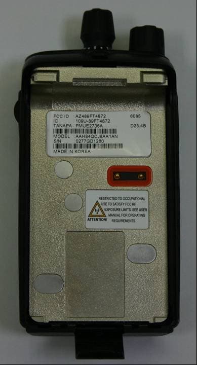
Click to zoom
Application Details
- Equipment Class
- TNF - Licensed Non-Broadcast Transmitter Held to Face
- Date of Grant
- Jul 26, 2006
- Application Purpose
- Original Equipment
- Date of Application
- Jul 26, 2006
- Equipment Note
- PORTABLE 2-WAY RADIO
- Frequency Range
- 403.00000000 - 425.00000000
- Company
- Motorola Solutions, Inc.
- Country
- United States
Documents & Files
Document Text
Text extracted from the exhibit documents filed with the FCC. Open a document above to read the original.
Users Manual
PRODUCT SAFETY AND RF EXPOSURE COMPLIANCE ATTENTION! This radio is restricted to occupational use only to satisfy FCC RF energy exposure requirements. Before using this product, read the RF energy awareness information and operating instructions in the Product Safety and RF Exposure booklet enclosed with your radio (Motorola Publication part number 6881095C98) to ensure compliance with RF energy exposure limits. For a list of Motorola-approved antennas, batteries, and other accessories, visit the following web site which lists approved accessories: http://www.motorola.com/governmentandenterprise Mag One™ by Motorola is registered in the U.S. Patent and Trademark Office. All other products and service names are the property of their own respective owners. © Motorola, Inc. 2005, 2006 1301 E. Algonquin Rd., Schaumburg, IL 60196 Printed in Korea. 03/06. All Rights Reserved. Before using this product, read the operating instructions for safe usage contained in the Product Safety and RF Exposure booklet enclosed with your radio. *6881098C61* 6881098C61-B Attaching and Removing the Antenna To Attach Antenna To Remove Antenna 1.Fasten the antenna to the radio by placing the threaded end of the antenna into the Antenna Connector. 2.Rotate the antenna clockwise until tight. 1.Turn the antenna in a counter-clockwise direction until it disengages from the radio. Threaded End of Antenna Antenna Connector Attaching and Removing the Battery To Attach Battery To Remove Battery 1.Align and fit the battery tongue into the groove of the chassis of the radio. 2.Secure the latch at the bottom of the radio. 1.Unlatch the battery clasp at the bottom of the radio. 2.Gently lift the hilt of the battery nearest to the battery latch away from the housing. 3.Slide battery downwards to remove. Attaching and Removing the Belt Clip To Attach Belt Clip To Remove Belt Clip 1.Align mounting rails of the radio with the grooves of the belt clip. 2.Slide the belt clip downwards until it clicks into place. 1.Lift the release tab. 2.Slide the belt clip upwards. Release Tab Charging your Radio 1.Turn off your radio and the A/C power sup- ply to your charger (if they are turned on). 2.Place your radio in the charger pocket. 3.Turn on the charger’s A/C power supply. 4.While charging your radio, the charger’s LED shows a steady red light. The radio should be charged at least 16 hours initially before decreasing charging time to 12 hours. 5.Turn off the charger’s A/C power supply, and remove the radio from the charger pocket. 6.For more details, refer to the Charger Manual (6881013Y27). Charger Pocket LED Indicators ColourStateIndication RedIlluminatedRadio is transmitting. BlinkingBattery voltage is low. GreenIlluminatedRadio is receiving with PL/DPL disabled. BlinkingRadio is in active scanning mode. OrangeIlluminatedRadio is receiving with PL/DPL enabled. BlinkingAn error has occured. On/Off and Volume Knob • Turn clockwise to turn radio ON and increase volume. • Turn counter-clockwise to decrease volume and turn radio OFF. Push-to-Talk (PTT) button • Press to transmit and release to receive messages. Speaker • Where received messages are heard. Microphone • Speak into microphone when send- ing message. Accessory Connector • To connect compatible acces- sories to radio. Programming Port • To program the radio. Accessories *Caution: Your radio does not support the VOX feature. Please set the accessory switch to ‘PTT’. If the accessory switch is set to ‘VOX’, your radio transmits constantly and never receives. TypesPart No.Description PMAD4050_RMag One 136-150MHz Antenna AntennaPMAD4051_RMag One 150-174MHz Antenna PMAE4019_RMag One 403-425MHz Antenna PMAE4020_RMag One 450-470MHz Antenna Audio AccessoryPMMN4008_Remote Speaker Microphone PMLN4442_Earbud with in-line mic and PTT/VOX * Switch PMLN4443_Ear Receiver with in-line mic and PTT/VOX* Switch PMLN4445_Ultra Lightweight Headset with In-line PTT/VOX * Switch PMLN4294_Earbud with Microphone & PTT Combined PMLN4605_Clear Acoustic Kit PMLN4606_2-Wire Surveillance Kit with Clear Acoustic Tube PMLN4658 _D-shell Earset with Boom Mic with PTT/VOX * Switch BatteryPMNN4071_RMag One NiMH batt 1200mAH Carry Accessory PMLN4743_Mag One Spring Belt Clip PMLN4691_RMag One Belt Clip PMLN4741_Mag One Soft Leather Carry Case PMLN4742_Mag One Hard Leather Carry Case ChargerPMLN4685_RMag One Mid-rate Charger Base Only PMLN4738_RMag One Mid-rate Charger Kit, 120 V PMLN4682_RMag One Slow Charger Base Only PMLN4683_RMag One Slow Charger Kit, 120 V PMLN4829_RMag One Mid-rate Transformer, 120 V PMLN4822_RMag One Slow Transformer, 120 V Channel Knob • Turn knob to change channel. Programmable Buttons • Frequently used features can be programmed here. LED Indicator • Colors indicate various states of the radio Programmable Buttons • The following functions can be assigned as short press (press and release) or long press (press and hold for 1 second) in the programmable buttons. † In Chirp Tone * Out Chirp Tone • Your radio’s default functions are described below. If re-programmed, enter the new functions . ButtonFunction High/Low Power Selects desired power level to High † or Low * . Volume SetAllows you to check the audio and alert tone volume level. MonitorAllows you to monitor the current channel for activity; disables squelch. Sticky Monitor * The radio monitors continually until you press this button again. Scan Starts * or Stops † channel scan. Nuisance Channel Delete † Removes unwanted channel(s) temporarily from scan list during scan. Repeater/Talkaround Toggles radio between functioning in Repeater mode † or Talkaround mode * . PL/DPL Enables † /Disables * radio from requiring matching PL/DPL to receive messages. Button Lock Locks * or unlocks † all buttons except PTT, Channel Knob and On/Off/Volume Knob. Battery Save Mode Toggles between functioning with Battery Saver ON * or Battery Saver OFF † . Squelch Selects desired squelch level: Normal † or Tight * . No OperationNo function is programmed…
Text truncated - open the document above for the full version.
Users Manual
Applicant: Motorola Inc. FCC ID: AZ489FT4872 EXHIBIT 9 SHEET 1 OF 1 EXHIBIT 9 INTERNAL PHOTOGRAPHS - Pursuant to 47 CFR 2.1033(c) 12 Figure 9-1: Top Side of PCB. Figure 9-2: Bottom Side of PCB.
Cover Letter(s)
FCC ID: AZ489FT4872 EXHIBIT 13A SHEET 1 Date: 25 th July 2006 Authorization & Evaluation Division Federal Communications Commission Laboratory 7435 Oakland Mills Road Columbia, MD 21046 Subject: Application for Certification of Transmitter with FCC ID: AZ489FT4872 Dear Sir / Madam, Motorola Inc., 8000 West Sunrise Blvd., Fort Lauderdale, FL, herein submits application for Certification of the equipment identified by FCC ID: AZ489FT4872. This transmitter is primarily intended for use in a portable radio application with capabilities for conventional communications with a conducted transmit power which is adjustable from 1 Watts to 4.5 Watts. The subject transmitter complies with CFR Title 47, Section 90.203, in that the operator cannot directly program the transmit frequencies using only the normally accessible external controls of the unit. Enclosed is a complete Certification Application. Please contact me if you require any additional information. Sincerely, /s/ Mike Ramnath (signed) Mike Ramnath Manager, Regulatory Compliance Email: [email protected]
Cover Letter(s)
FCC ID: AZ489FT4872 EXHIBIT 13B SHEET 1 REQUEST FOR CONFIDENTIALITY Date: 25 th July 2006 Authorization & Evaluation Division Federal Communications Commission Laboratory 7435 Oakland Mills Road Columbia, MD 21046 Subject: Application for Certification of Transmitter with FCC ID: AZ489FT4872 Dear Sir / Madam, Motorola is requesting that Exhibit 4 (Circuit Descriptions), Exhibit 5 (Schematic Diagrams), Exhibit 10 (Parts List and Tune Up Procedures), and Exhibit 12 (Operational Description) not be made routinely available for public inspection. Motorola considers the information in these exhibits to be classified as trade secrets, pursuant to 47 CFR Section 0.457(d) and Section 552(b)(4) of the Freedom of Information Act. Please mark Exhibits 4, 5, 10 and 12 as “Confidential.” Please contact me if you require any additional information. Sincerely, /s/ Mike Ramnath (signed) Mike Ramnath Manager, Regulatory Compliance Email: [email protected]
External Photos
Applicant: Motorola Inc. FCC ID: AZ489FT4872 EXHIBIT 3 SHEET 1 OF 7 EXHIBIT 3 EXTERNAL PHOTOGRAPHS - Pursuant to 47 CFR 2.1033(c) 12 Figure 3-1: Front view of complete radio Applicant: Motorola Inc. FCC ID: AZ489FT4872 EXHIBIT 3 SHEET 2 OF 7 Figure 3-2: Back view of complete radio Applicant: Motorola Inc. FCC ID: AZ489FT4872 EXHIBIT 3 SHEET 3 OF 7 Figure 3-3: Right side (side connector) view of complete radio Applicant: Motorola Inc. FCC ID: AZ489FT4872 EXHIBIT 3 SHEET 4 OF 7 Figure 3-4: Left side (PTT) view of complete radio Applicant: Motorola Inc. FCC ID: AZ489FT4872 EXHIBIT 3 SHEET 5 OF 7 Figure 3-5: Rear view of complete radio showing FCC Label & RF Safety Label location FCC Label Location RF Safety Label Location Applicant: Motorola Inc. FCC ID: AZ489FT4872 EXHIBIT 3 SHEET 6 OF 7 Figure 3-6: Top view of complete radio Figure 3-7: Close-up view of RF Safety Label Applicant: Motorola Inc. FCC ID: AZ489FT4872 EXHIBIT 3 SHEET 7 OF 7 Figure 3-8: Type of Antenna; Helical Antenna (PMAE4019A) Model List Model Name Plate Tanapa Number Description AAH84QCJ8AA1AN LAH84QCC8AA4AN AZH84QCC8AA3 MDH84QCC8AA3AN BPR40 A8 A8 MP300 PMUE2736A PMUE2387A PMUE2387A PMUE2387A UHF 403-425MHz , 12.5/25kHz, 1 – 4.5 Watt (NA) UHF 403-425MHz , 12.5/25kHz, 1 – 4.5 Watt (LACR) UHF 403-425MHz , 12.5/25kHz, 1 – 4.5 Watt (APAC) UHF 403-425MHz , 12.5/25kHz, 1 – 4.5 Watt (EMEA)
ID Label/Location Info
Applicant: Motorola Inc. FCC ID: AZ489FT4872 EXHIBIT 1 SHEET 1 OF 1 EXHIBIT 1 IDENTIFICATION LABEL - Pursuant to 47 CFR 2.925(a), 2.1033(c), 2.0165 EXHIBIT 1A - LABEL LOCATION A nameplate of the type presented below will be affixed to every transmitter. It will be placed on the bottom of the unit near the front. Shown below is a photo of the actual label affixed to the cast chassis of the transmitter. Figure 1-1: FCC Label EXHIBIT 1B - GENERAL INFORMATION 1. Application References: TIA/EIA-603B Land Mobile FM or PM Communications Equipment Measurement and Performance Standards Code of Federal Regulations Title 47, Part 2, Sec. 2.1033-2.1057 and Part 90, Section 90.210. 2. Data Submittal Procedure: Data is supplied in accordance with Part 2, Sub-part J of the Commission’s rules. The intended use of this transceiver includes applications covered in the Code of Federal Regulations Title 47 and Part 90. Maximum transmitter power shall not be adjustable by the user. 3. Applicable Reference • Reference Certification FCC ID: AZ489FT4872 • EIA/TIA-603 Land Mobile FM or PM Communications Equipment Measurement and Performance Standards. • FCC Federal Regulations Part 47 Sec. 2.1033-2.1057 • FCC Federal Regulations Part 90 Sec.90.210
Internal Photos
Applicant: Motorola Inc. FCC ID: AZ489FT4872 EXHIBIT 9 SHEET 1 OF 1 EXHIBIT 9 INTERNAL PHOTOGRAPHS - Pursuant to 47 CFR 2.1033(c) 12 Figure 9-1: Top Side of PCB. Figure 9-2: Bottom Side of PCB.
RF Exposure Info
FCC ID: AZ489FT4872 SR3785 GEMS EME Form-SAR-Rpt-Rev. 4.01 Page 1 of 48 Certificate Number: 1449-01 FCC ID: AZ489FT4872 DECLARATION OF COMPLIANCE SAR ASSESSMENT Networks & Enterprise EME Test Laboratory 8000 West Sunrise Blvd Fort Lauderdale, FL. 33322 Date of Report: 4/7/06 Report Revision: Rev O Report ID: FCC rpt_Alpha L UHF R1_060407_SR3785 Responsible Engineer: Michael Sailsman (Sr. Staff Eng.) Date/s Tested: 3/22/06-3/27/06 Manufacturer/Location: Motorola – Penang Sector/Group/Div.: NE/GTDG Date submitted for test: 3/15/06 DUT Description: Alpha L 4W 12.5/25K-16CH NA Test TX mode(s): CW Max. Power output: 4.5W Nominal Power: 4.0W Tx Frequency Bands: 403-425MHz Signaling type: FM Model(s) Tested: PMUE2736A/AAH84QCJ8AA1AN Model(s) Certified: PMUE2736A/AAH84QCJ8AA1AN Serial Number(s): 0277GD1253, 0277GD1256 Classification: Occupational/Controlled Rule Part(s): 90 Approved Accessories: Antenna(s): PMAE4019A (403-425MHz ¼ wave, -3dBi); PMAE4019AR (403-425MHz ¼ wave, -3dBi) Battery(ies): PMNN4071ARC (Mag One NiMH, 1200mAH: CHN-LBL, Boxed); PMNN4071A (Mag One NiMH, 1200mAH), PMNN4071AR (Mag One NiMH, 1200mAH: Boxed); PMNN4071AC (MAG One NiMH, 1200mAH: CHN-LBL) Body worn accessory(ies): PMLN4743A (Spring belt); PMLN4691A (Standard belt clip); PMLN4741A (soft leather carry case); PMLN4742A (hard leather carry case) Audio/Data cable accessory(ies): PMMN4008A (Remote speaker microphone); PMLN4442A (Earbud w/ in-line mic and PTT/VOX switch); PMLN4443A (Ear receiver w/ in- line mic and PTT/VOX switch); PMLN4444A (Earphone Boom mic w/ in-line mic and PTT/VOX); PMLN4445A (Ultra lightweight headset w/ in-line PTT/VOX switch); PMLN4294C (Earbud w/ combined microphone and PTT); PMLN4606A (2-wire surveillance kit w/ clear acoustic tube); PMLN4605A (Clear Acoustic kit); PMLN4658A (D-shell earset w/ boom mic & PTT/VOX switch Max. Calc. 1-g/10-g Avg. SAR: 6.00/4.16 W/kg (Body) Max. Calc. 1-g/10-g Avg. SAR: 3.84/2.76 W/kg (Face) Based on the information and the testing results provided herein, the undersigned certifies that when used as stated in the operating instructions supplied, said product complies with the national and international reference standards and guidelines listed in section 2.0 of this report. This report shall not be reproduced without written approval from an officially designated representative of the Motorola EME Laboratory. This reporting format is consistent with the test report guidelines of the TIA TSB-150 December 2004 The results and statements contained in this report pertain only to the device(s) evaluated. Deanna Zakharia’s signature on file Ken Enger GEMS EME Lab Senior Resource Manager, Laboratory Director, Approval Date: 4/7/06 Certification Date: 4/7/06 Certification No.: L1060431 FCC ID: AZ489FT4872 SR3785 GEMS EME Form-SAR-Rpt-Rev. 4.01 Page 2 of 48 1.0 Introduction and Overview...................................................................................... 3 2.0 Referenced Standards and Guidelines ..................................................................... 3 2.1 SAR Limits ................................................................................................... 4 3.0 Description of Device Under Test (DUT) ............................................................... 4 4.0 Description of Test System ..................................................................................... 5 4.1 Description of Robotics/Probes/Readout Electronics ................................... 5 4.2 Description of Phantom(s) ............................................................................ 5 4.2.1 Flat Phantom................................................................................... 5 4.2.2 SAM Phantom ................................................................................ 6 4.3 Description of Equivalent Tissues ................................................................ 6 5.0 Additional Test Equipment...................................................................................... 7 6.0 SAR Measurement System Verification.................................................................. 7 6.1 Equivalent Tissue Test results ...................................................................... 7 6.2 System Check Test results ............................................................................ 8 7.0 DUT Test Strategy and Methodology ..................................................................... 8 7.1 DUT Configuration(s) .................................................................................. 8 7.2 Device Positioning Procedures ..................................................................... 9 7.2.1 Body ............................................................................................... 9 7.2.2 Head ............................................................................................... 9 7.2.3 Face ................................................................................................ 9 8.0 Environmental Test Conditions ............................................................................. 10 9.0 Test Results Summary ........................................................................................... 10 9.1 Highest SAR results calculation methodology ........................................... 12 10.0 Conclusion............................................................................................................. 12 APPENDICES A Measurement Uncertainty ..................................................................................... 13 B Probe Calibration Certificates ............................................................................... 16 C Dipole Calibration Certificates.............................................................................. 25 D Test System Verification Scans ............................................................................. 30 E DUT Scans (Highest SAR configurations)...........................…
Text truncated - open the document above for the full version.
Test Report
Applicant: Motorola Inc. FCC ID: AZ489FT4872 EXHIBIT 6 SHEET 1 OF 32 EXHIBIT 6 INDEX OF SUBMITTED MEASURED DATA This exhibit contains the measured data for this equipment as follows: EXHIBIT 6A – RF Power Output (Table) EXHIBIT 6B – Transmit Audio Response (2 Graphs) 6B-1 – 12.5 kHz Channel Spacing 6B-2 – 25 kHz Channel Spacing EXHIBIT 6C – Transmit Audio Post Limiter Low-pass Filter Response (2 Graphs) 6C-1 – 12.5 kHz Channel Spacing 6C-2 – 25 kHz Channel Spacing EXHIBIT 6D – Modulation Limiting Characteristics (6 Graphs) 6D-1 – 12.5 kHz Channel Spacing, Carrier Squelch Mode 6D-2 – 12.5 kHz Channel Spacing, Tone Private Line (TPL) Mode 6D-3 – 12.5 kHz Channel Spacing, Digital Private Line (DPL) Mode 6D-4 – 25 kHz Channel Spacing, Carrier Squelch Mode 6D-5 – 25 kHz Channel Spacing, Tone Private Line (TPL) Mode 6D-6 – 25 kHz Channel Spacing, Digital Private Line (DPL) Mode EXHIBIT 6E – Occupied Bandwidth (6 Spectrum Analyzer Plots) 6E-1 - 12.5 kHz Channel Spacing, 2500 Hz Audio Modulation Only 6E-2 - 12.5 kHz Channel Spacing, 2500 Hz Audio and PL Tone Modulation 6E-3 - 12.5 kHz Channel Spacing, 2500 Hz Audio and DPL Tone Modulation 6E-4 - 25 kHz Channel Spacing, 2500 Hz Audio Modulation Only 6E-5 - 25 kHz Channel Spacing, 2500 Hz Audio and PL Tone Modulation 6E-6 - 25 kHz Channel Spacing, 2500 Hz Audio and DPL Tone Modulation EXHIBIT 6F – Conducted Spurious Emissions (12 Graphs) 6F-1 – 1 Watts, Harmonic of Carrier 403.025 MHz, 12.5 kHz Channel Spacing 6F-2 – 1 Watts, Harmonic of Carrier 414.025 MHz, 12.5 kHz Channel Spacing 6F-3 – 1 Watts, Harmonic of Carrier 424.975 MHz, 12.5 kHz Channel Spacing 6F-4 – 4.5 Watts, Harmonic of Carrier 403.025 MHz, 12.5 kHz Channel Spacing 6F-5 – 4.5 Watts, Harmonic of Carrier 414.025 MHz, 12.5 kHz Channel Spacing 6F-6 – 4.5 Watts, Harmonic of Carrier 424.975 MHz, 12.5 kHz Channel Spacing 6F-7 – 1 Watts, Harmonic of Carrier 403.025 MHz, 25 kHz Channel Spacing 6F-8 – 1 Watts, Harmonic of Carrier 414.025 MHz, 25 kHz Channel Spacing 6F-9 – 1 Watts, Harmonic of Carrier 424.975 MHz, 25 kHz Channel Spacing 6F-10 – 4.5 Watts, Harmonic of Carrier 403.025 MHz, 25 kHz Channel Spacing 6F-11 – 4.5 Watts, Harmonic of Carrier 414.025 MHz, 25 kHz Channel Spacing 6F-12 – 4.5 Watts, Harmonic of Carrier 424.975 MHz, 25 kHz Channel Spacing Applicant: Motorola Inc. FCC ID: AZ489FT4872 EXHIBIT 6 SHEET 2 OF 32 EXHIBIT 6G – Radiated Spurious Emissions (12 Graphs) 6G-1 – 4.5 Watts, 403.025 MHz, 12.5 kHz Channel Spacing & 4.5 Watts, 414.025 MHz, 12.5 kHz Channel Spacing 6G-2 – 4.5 Watts, 424.975 MHz, 12.5 kHz Channel Spacing 6G-3 – 4.5 Watts, 403.025 MHz, 25 kHz Channel Spacing & 4.5 Watts, 414.020 MHz, 25 kHz Channel Spacing 6G-4 – 4.5 Watts, 424.975 MHz, 25 kHz Channel Spacing 6G-5 – 1 Watts, 403.025 MHz, 12.5 kHz Channel Spacing & 1 Watts, 414.025 MHz, 12.5 kHz Channel Spacing 6G-6 – 1 Watts, 424.975 MHz, 12.5 kHz Channel Spacing 6G-7 – 1 Watts, 403.025 MHz, 25 kHz Channel Spacing & 1 Watts, 414.0250 MHz, 25 kHz Channel Spacing 6G-8 – 1 Watts, 424.975 MHz, 25 kHz Channel Spacing EXHIBIT 6H – Frequency Stability (2 Graphs) 6H-1 – Frequency Stability vs. Temperature 6H-2 – Frequency Stability vs. Voltage EXHIBIT 6I – Transient Frequency Behavior (8 Graphs) 6I-1 – 4.5 Watts, 12.5 kHz Key-Up Attack Time 6I-2 – 4.5 Watts, 12.5 kHz De-Key Decay Time 6I-3 – 4.5 Watts, 25 kHz Key-Up Attack Time 6I-4 – 4.5 Watts, 25 kHz De-Key Decay Time 6I-5 – 1 Watts, 12.5 kHz Key-Up Attack Time 6I-6 – 1 Watts, 12.5 kHz De-Key Decay Time 6I-7 – 1 Watts, 25 kHz Key-Up Attack Time 6I-8 – 1 Watts, 25 kHz De-Key Decay Time EXHIBIT 6J – Power Line Conducted Spurious Emissions (4 Graphs) 6J-1 – Radio off Line/Neutral 6J-2 – Radio on Rx Line/Neutral 6J-3 – Radio on Tx Line/Neutral Applicant: Motorola Inc. FCC ID: AZ489FT4872 EXHIBIT 6 SHEET 3 OF 32 EXHIBIT 6A RF Conducted Power Output Data -- Pursuant 47 CFR 2.1046(a), 2.1033(c)(6), 2.1033(c)(7) and 2.1033(c)(8) The RF power output was measured with the indicated voltage applied to and current into the final RF amplifying device (Q403). At maximum output power setting, Frequency 403.025 MHz: Output RF power 4.5 Watts DC Voltage 7.5 Volts DC Current 1.41 A DC Input Power 10.58 Watts At minimum output power setting, Frequency 403.025 MHz: Output RF power 1.04 Watts DC Voltage 7.5 Volts DC Current 0.50 A DC Input Power 3.75 Watts At maximum output power setting, Frequency 414.025 MHz: Output RF power 4.50 Watts DC Voltage 7.5 Volts DC Current 1.40 A DC Input Power 10.5 Watts At minimum output power setting, Frequency 414.025 MHz: Output RF power 1.07 Watts DC Voltage 7.5 Volts DC Current 0.49 A DC Input Power 3.68 Watts At maximum output power setting, Frequency 424.975 MHz: Output RF power 4.50 Watts DC Voltage 7.5 Volts DC Current 1.39 A DC Input Power 10.43 Watts At minimum output power setting, Frequency 424.975 MHz: Output RF power 1.11 Watts DC Voltage 7.5 Volts DC Current 0.49 A DC Input Power 3.68 Watts Applicant: Motorola Inc. FCC ID: AZ489FT4872 EXHIBIT 6 SHEET 4 OF 32 EXHIBIT 6B Transmit Audio Response - Pursuant 47 CFR 2.1047 and 2.1033(c)(13) TX. AUDIO FREQUENCY RESPONSE (12.5 kHz Channel Spacing) -15.0 -10.0 -5.0 0.0 5.0 10.0 15.0 100100010000 Mod.Freq.(Hz) Audio (db) audio response Spec . Hi Spec . Lo Figure 6B-1: 12.5 kHz Channel Spacing, 414.025 MHz, Transmit Audio Frequency Response TX. AUDIO FREQUENCY RESPONSE (25 kHz Channel Spacing) -15.0 -10.0 -5.0 0.0 5.0 10.0 15.0 100100010000 Mod.Freq.(Hz) Audio (db) audio response Spec . Hi Spec. Lo Figure 6B-2: 25 kHz Channel Spacing, 414.025 MHz, Transmit Audio Frequency Response Applicant: Motorola Inc. FCC ID: AZ489FT4872 EXHIBIT 6 SHEET 5 OF 32 EXHIBIT 6C Transmit Audio Post Limiter Low pass Filter Response - Pursuant 47 CFR 2.1047 and 2.1033(c) (13) freq Hz 1000 10000 100000 Attenuation dB -20 -10 0 -30 -40 -50 -60 -70 -80 AUDIO LOW PASS FILTER RESPONSE 12.5KHz 12.5 KHz limits -90 Figure 6C-1: 12.5 kHz Channel Spacing, 414.025 MHz, Transmit Audio Lowpass Filter Response freq Hz 1000 10000 100000 A…
Text truncated - open the document above for the full version.
Test Report
Applicant: Motorola Inc. FCC ID: AZ489FT4872 EXHIBIT 7 SHEET 1 OF 4 EXHIBIT 7 MEASUREMENT PROCEDURES USED FOR SUBMITTED DATA EXHIBIT 7A - RF Output Power vs. DC Power Input - Pursuant to 47 CFR 2.1046 The transmitter is operated under normal conditions at the specified nominal DC input voltage. The antenna output is terminated in 50 ohms. The DC supply path to the final stage only is interrupted to allow insertion of the DC ammeter in series with the DC supply. The DC voltage drop of the ammeter is negligible. A DC voltmeter is computed as the product of the DC current (in amps) times the DC voltage (in volts). This measurement is performed at the upper, middle and lower limits of the frequency range. At each frequency, the measurement is performed at the upper and lower limits of the specified adjustable power range. EXHIBIT 7B - Transmit Audio Frequency Response – Pursuant to 47 CFR 2.1047(a) The transmitter output is monitored with an HP8901B modulation analyzer, whose FM demodulator output is fed to an HP8903B audio analyzer. De-emphasis or filtering within the test equipment is not used. An audio oscillator signal, derived from the HP8903B Audio Analyzer, is connected to the microphone audio input of the transmitter. At a frequency of 1 kHz, the level is adjusted to obtain 20% of full system deviation, to ensure that limiting does not occur at any frequency in the range of 300 Hz – 3000 Hz. A constant input level is then maintained and the oscillator frequency is varied between the ranges of 100 Hz to 5000 Hz. The frequency response is plotted, using a reference of 0 dB at 1 kHz. EXHIBIT 7C - Transmit Audio Post Limiter Low Pass Filter Response – Pursuant to 47 CFR 2.1047(a) The audio oscillator portion of an HP8903B audio analyzer is connected to the input of the post limiter low pass filter. The oscillator is adjusted, at 1000 Hz and level 20dB greater than that required to produce standard test modulation. The output of the low pass filter is measured with an HP35665A dynamic signal analyzer. The response is swept between the limits of 1000 Hz - 30000 Hz. Oscillator level is chosen to be as high as possible and that will not cause limiting at any frequency, and maintaining a constant input level versus frequency. EXHIBIT 7D – Modulation Limiting Characteristic – Pursuant to 47 CFR 2.1047(d) An audio oscillator is connected to the microphone audio input. The transmitter output is monitored with an HP8901B modulation analyzer. The flat frequency response FM demodulator output of the HP8901B is fed to an HP8903B audio analyzer. The 20 kHz low pass filter of the modulation analyzer is used to reduce the level of residual high frequency noise. The oscillator level is adjusted, at 1 kHz, to obtain 60% of full system deviation. The oscillator level is then varied over a range of +/-25dB in 5dB increments, and the resulting deviation is plotted. This measurement is repeated at 300 Hz and 3 kHz. The above procedure is performed three times, for conditions with Tone Private Line, Digital Private Line, and Carrier Squelch Mode (without sub-audible signaling). EXHIBIT 7E - Occupied Bandwidth - Pursuant to 47 CFR 2.1049(c) (i) Procedure for Occupied Bandwidth for Voice Transmission An audio oscillator is connected to the microphone audio input. The frequency is set to 2500 Hz and the amplitude is adjusted to a level 16dB above that is required to produce 50% of full system deviation at the frequency of maximum response of the audio modulation circuit, in accordance with FCC rules Part 2.1049(c)(1). Applicant: Motorola Inc. FCC ID: AZ489FT4872 EXHIBIT 7 SHEET 2 OF 4 The transmitter output is connected, via a 30 dB attenuator, which also provides a 50-ohm termination to the transmitter output, to an HP8560E spectrum analyzer that outputs directly to a computer. Spectrum analysis of the transmitter output is performed to at least +/-2.5 times the channel spacing. The unmodulated carrier is used to establish a 0-dB reference, then with the modulating signal applied. This 0 dB reference is equivalent to the power rating of the transmitter, which is specified in each page of the exhibit. This measurement is repeated with Tone Private Line continuous sub-audible signaling added (250.3 Hz at 15% full system deviation) and again with Digital Private Line (code 131 at 15% of full system deviation) for both channel spacing, 12.5 kHz and 25 kHz. EXHIBIT 7F - Conducted Spurious Emissions - Pursuant to FCC Rule 2.1051 The output of the transmitter is connected, via a suitable attenuator, to the input of an HP 8563E spectrum analyzer. This data is measured at the lower, mid and upper frequency limits of the frequency range. If transmit power is adjusted, the measurement is repeated at various power levels including minimum and maximum. EXHIBIT 7G - Radiated Spurious Emissions - Pursuant to 47 CFR 2.1053 Transmitter radiated spurious emissions were measured by Motorola Plantation EMC Lab. Measurements were made at an approved open field test site constructed in accordance with Appendix B, FCC/OST 55 (1982), and were performed in accordance with the Code of Federal Regulations, Title 47, Part 2, paragraph 2.1053. The data is plotted as “Radiated Spurious Emissions” on the graphs comprising EXHIBIT 6G. The specification limit corresponding to a level of 43 dB + 10log(Pout) for 25kHz Channel Spacing and 50 dB + 10log(Pout) for 12.5kHz Channel Spacing below the fundamental carrier power of the transmitter as indicated on each graph for reference. The test site is: Motorola Plantation EMC Lab, located in Florida, United States of America. Motorola Plantation EMC Lab is listed with FCC and Industry Canada as follows: 1. FCC OATS registration number is: 91932 2. Industry Canada OATS registration number is: IC 3679 Site address: 8000 West Sunrise Blvd. Plantation, Florida 33322 EXHIBIT 7H – Frequency Stability vs. Temperature and vs. Voltage - Pursuant to 47 CFR 2.1055(a) (d) Frequency Stability vs. Temperature data…
Text truncated - open the document above for the full version.
Contact Information
Applicant
Arine Lee(Certification Manager)
Test Firm
MotorolaWilliam Elliott
Technical Specifications
| # | Rule Parts | Frequency Range | Power Output | Emission | Tolerance |
|---|---|---|---|---|---|
| 4 | 90,90.21 | 403 MHz - 425 MHz | 1 W | 16K0F3E | 2.5 ppm |
Other Applications from Motorola Solutions, Inc.

AZ489FT4980
Sep 08, 2026Portable two way radio
Equipment Class
TNF - Licensed Non-Broadcast Transmitter Held to FaceAZ489FT4981
Aug 14, 2026Handheld Portable - TANAPA BPR 45 400-470 MHZ 4W NKP
Equipment Class
TNF - Licensed Non-Broadcast Transmitter Held to Face
AZ489FT7187
Jul 13, 2026Portable 2-Way Radio with Bluetooth, Bluetooth LE, WIFI 2.4GHz, WIFI 5GHz, LTE
Equipment Class
DSS - Part 15 Spread Spectrum TransmitterAZ499FT6031
May 11, 2026Operation Critical Wireless Earpiece PTT
Equipment Class
DSS - Part 15 Spread Spectrum Transmitter
AZ499FT5879
Dec 19, 20252-way Portable Radio with BT, BTLE, WIFI, NFC and LTE
Equipment Class
DSS - Part 15 Spread Spectrum Transmitter