AZ489FT4879PORTABLE TWO-WAY RADIO
Motorola Solutions, Inc.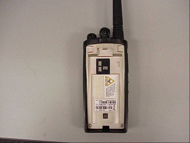
Click to zoom
Application Details
- Equipment Class
- TNF - Licensed Non-Broadcast Transmitter Held to Face
- Date of Grant
- Mar 13, 2007
- Application Purpose
- Original Equipment
- Date of Application
- Mar 13, 2007
- Equipment Note
- PORTABLE TWO-WAY RADIO
- Frequency Range
- 450.00000000 - 470.00000000
- Company
- Motorola Solutions, Inc.
- Country
- United States
Documents & Files
Document Text
Text extracted from the exhibit documents filed with the FCC. Open a document above to read the original.
Users Manual
-1 6864110R04b.book Page -1 Friday, October 20, 2006 4:38 PM 0 6864110R04b.book Page 0 Friday, October 20, 2006 4:38 PM 1 Introduction RDX Introduction Thank you for purchasing a Motorola ® RDX Series Radio. Your radio is a product of Motorola’s 70 plus years of experience as a world leader in the designing and manufacturing of communications equipment. The RDX Series radios provide cost- effective communications for businesses such as retail stores, restaurants, schools, construction sites, manufacturing, pr operty and hotel management and more. Motorola professional two-way radios are the perfect communications solution for all of today’s fast-paced industries.Note: Please read this manual carefully to ensure you know how to properly operate the radio before use. Package Contents •Radio• Spring Action Belt Clip• Lithium Ion Battery • 10-Hour Charger • User's Guide• Warranty Card• Drop-In Charging Tray (not included with all models) 6864110R04b.book Page 1 Friday, October 20, 2006 4:38 PM Introduction 2 RDX For product-related questions, please contact: 1-800-448-6686 in the USA1-800-461-4575 in Canada1-888-390-6456 on your TTY (Text Telephone) On the web, please refer to: www.motorola.com/radios/professional 6864110R04b.book Page 2 Friday, October 20, 2006 4:38 PM Contents 3 ContentsIntroduction ...................................1 FCC Licensing Information ..........5 Safety and General Information ...............................7 Getting Started ............................17 Installing the Swivel Belt Holster ..................................18 Installing the Nickel-Metal Hydride Battery .....................19 Charging the XSeries Radio ....20Turning Your Radio On or Off......................................21 Adjusting the Volume ................21Using the Radio ........................21Understanding the Display........23 Battery and Charging Options ...................................24 NiMH Battery.............................24Alkaline Batteries ......................24Charging with the Drop-in Charging Tray ........................25 Reading the Batter y Meter ........26 Battery Life................................26XTN Series Factory Defaults ....27 Talking and Receivin g ............... 28 Signal Strength Indicator/ Channel Busy........................ 28 Talk Range ............................... 28Keypad Lock............................. 29Hands-Free Use/VOX .............. 29With Compatible VOX Accessories........................... 29 Without Accessories................. 30Setting VOX Sensitivity ............ 30Monitoring a Channel ............... 31Scanning ................................. 31 Programming Features ...............32 Entering Programming Mode ....32Programming a Channel ..........34Programming the Frequency.....34Programming the Interference Eliminator Code......................35 Assigning Channels to Presets ..............................35 Programming the Scramble Feature...................................36 Programming Bandwidth ..........36Programming the Available Channel .................................37 6864110R04b.book Page 3 Friday, October 20, 2006 4:38 PM Contents 4 Programming Call Tones ......... 37Programming Microphone Gain ....................................... 38 Editing the Scan List ................ 38Cloning ...................................... 39 Advanced Features ......................... 41 Troubleshooting ............................. 43 Use and Care .................................... 45 Frequencies and Bandwidths......... 47Verifying the M-Series Frequency and Code Setting ...... 53 Motorola Limited Warranty .............55 Software Copyright Notice ..............63 Patent Notice..................................63 Export Law Assurances ..................64 Index .................................................66 6864110R04b.book Page 4 Friday, October 20, 2006 4:38 PM 5 FCC Licensing Information FCC FCC Licensing Information RDX Series professional two-way radios ope rate on radio frequencies that are regulated by the Federal Communications Commission (FCC). In order to transmit on these frequencies, you are required to have a license issued by the FCC.Application is made available on FCC Form 601 and Schedules D, H, and Remittance Form 159.To obtain these FCC forms please request document 000601 which includes all forms and instructions. If you wish to have the document faxed, mailed or have questions, please use the following contact information. Before filling out your applic ation, you must decide wh ich frequency(ies) you can operate on. See Frequencies and Bandwidths.For questions on determining your radio frequency, please call Motorola Product Services at: 1-800-448-6686. Faxed contact the Fax-On- Demand system at: Mailed call the FCC forms hotline at: Questions regarding FCC license contact the FCC at: 1-202-418-0177 1-800-418-FORM 1-800-418-3676 1-888-CALL-FCC 1-888-225-5322 Or: http://www.fcc.gov 6864110R04b.book Page 5 Friday, October 20, 2006 4:38 PM FCC Licensing Information 6 FCC Changes or modifications not expressly ap proved by Motorola may void the user’s authority granted by the FCC to operat e this radio and should not be made. To comply with FCC requirements, transmitter adjustments should be made only by or under the supervision of a person certified as technically qualified to perform transmitter maintenance and repairs in the private land mobile and fixed services as certified by an organization representative of the user of those services. Replacement of any transmitter componen t (crystal, semiconductor, etc.) not authorized by the FCC equipment authorization for this radio could violate FCC rules.Note: Use of this radio outside the country wh ere it was intended to be distributed is subject to government regulations and may be prohibited. 6864110R04b.book Page 6 Friday, October 20, 2006 4:38 PM Safety and General Information 7 IMPORTANT SAFETY INSTRUCTIONS SAVE THESE INSTRUCTIONS This docume…
Text truncated - open the document above for the full version.
Cover Letter(s)
FCC ID: AZ489FT4879 Networks and Enterprise 8000 West Sunrise Boulevard, Fort Lauderdale, Florida 33322. 6 th March 2007 Authorization and Evaluation Division Federal Communications Commission Laboratory 7435 Oakland Mills Road Columbia. MD 21046 Subject: Application for Certification of Transmitter with FCC ID: AZ489FT4879. Gentlemen: Motorola Inc, 8000 West Sunrise Boulevard, Fort Lauderdale, Florida, herein submits application for Certification of the subject transmitter. This transmitter is primarily intended to be use in a portable radio application with capabilities for clear communications with transmit output power of 1-2.0 Watts (Nominal) and 2.35 Watts (Max Power). The Product names are RDU2020 and RDU2080d. The subject transmitter complies with Section 90.203 of the rules in that the operator cannot directly program transmit frequencies using only the unit’s normally accessible external controls. Enclosed is a complete Type Acceptance Application. Contact me (954) 723-5793 or Fax me at (954) 723-4794, if you require any additional information. Sincerely, /s/ Mike Ramnath (signed) Mgr, Regulatory Compliance Email: [email protected]
Cover Letter(s)
EXHIBIT 13B FCC ID: AZ489FT4879 REQUEST FOR CONFIDENTIALITY Date: 6 th March 2007 Authorization & Evaluation Division Federal Communications Commission Laboratory 7435 Oakland Mills Road Columbia, MD 21046 Subject: Application for Certification of Transmitter with FCC ID: AZ489FT4879 Dear Sir / Madam, Motorola is requesting that Exhibit 4 (Circuit Descriptions), Exhibit 5 (Schematic Diagrams), Exhibit 10 (Parts List and Tune-Up Procedures), and Exhibit 12 (Transmitter Description) not be made routinely available for public inspection. Motorola considers the information in these exhibits should be classified as trade secrets, pursuant to 47 CFR Section 0.457(d) and Section 552(b)(4) of the Freedom of Information Act. We are also requesting that the FCC mark Exhibit 3 (External Photos), Exhibit 8 (Users Manual) and Exhibit 9, (Internal Photos) as Temporary Confidentiality as outlined in Public Notice DA 04-1705, dated June 15, 2004. This provision will give Motorola temporary confidentiality prior to product launch. Please mark Exhibits 4, 5, 10, and 12 as “Confidential” And Exhibit 3, 8 and 9 as “Temporary Confidential”. Please contact me if you require any additional information. Sincerely , /s/ Mike Ramnath (signed) Mike Ramnath Manager, Regulatory Compliance Email: [email protected]
External Photos
FCC ID: AZ489FT4879 EXTERNAL PHOTOGRAPHS: 1 Front view of Radio 2 Rear view of radio without battery cover. 3 Magnified view of FCC Label. EXHIBIT 3 FCC ID: AZ489FT4879 EXHIBIT 3-A FCC ID: AZ489FT4879 EXHIBIT 3-B FCC ID: AZ489FT4879 EXHIBIT 3-C
ID Label/Location Info
FCC ID: AZ489FT4879 IDENTIFICATION LABEL LOCATION X See the attached Photograph, and Exhibit 3-D for the location of the Label on the device. Back of Radio Back of Radio under Belt Clip Please note that Motorola complies with FCC Rule Part 2.925 (d) that the label is permanently affixed and is readily visible to the purchaser at the time of purchase. TYPE X The label is a paper polyester film laminate with a pressure sensitive adhesive backing. The adhesive is a permanent type acrylic with minimum peel strength of 40 oz/ inch. The label is laser etched into the Urethane paint, exposing the Nickel plating on the Zamak casting substrate. Since no adhesive is required, the label is permanent and tamper-proof. (** - NOTE- The label attached below is a paper polyester film laminate, as described above. This is just for sample purposes, as the actual label is laser etched into the casting) MARKINGS (TEXT) See Photograph, Exhibit 1. EXHIBIT 1 FCC ID: AZ489FT4879 GENERAL INFORMATION I. Production Plans—Pursuant 2.983 ( c ). Quantity production is planned. II. Application References -- Pursuant 2.1061 Reference is made to the following Motorola “Application References” 1. Portable Products and their application. 2. Portable Products Transmitter Modulations Methods. III. Data Submittal Procedure: Data is supplied in accordance with Part 2, Sub-part J of the Commissions’ Rules. EXHIBIT 1A FCC ID: AZ489FT4879 Rear Casting FCC Label Placement RF Safety label Factory label / FCC Label
Internal Photos
FCC ID: AZ489FT4879 INTERNAL PHOTOGRAPHS: Printed Circuit Board 1 Component (Front) 2 Non components Side (Rear) EXHIBIT 9 FCC ID: AZ489FT4879 EXHIBIT 9-A FCC ID: AZ489FT4879 EXHIBIT 9-B
RF Exposure Info
FCC ID: AZ489FT4879 SR4592 N&E EME Form-SAR-Rpt-Rev. 5.05 Page 1 of 52 Certificate Number: 2518.01 FCC ID: AZ489FT4879 DECLARATION OF COMPLIANCE SAR ASSESSMENT Networks & Enterprise EME Test Laboratory 8000 West Sunrise Blvd Fort Lauderdale, FL. 33322 Date of Report: 11/28/06 Report Revision: O Report ID: RDU2020_RLN6171A_Rev O_061128 SR4592 Responsible Engineer: Kim Uong (EME lead Eng.) Date/s Tested: 11/13/06 -11/15/06 Manufacturer/Location: Motorola Sector/Group/Div.: CPD Date submitted for test: 11/10/06 DUT Description: RDU2020 UHF RBR, 2Ch, Fixed Antenna, 2.0Watts, Black, Li-Ion. Test TX mode(s): CW Max. Power output: 2.35 Watts Nominal Power: 2.0 Watts Tx Frequency Bands: 451.18750MHz - 469.56250MHz Signaling type: FM Model(s) Tested: RLN6171A Model(s) Certified: RLN6171A Serial Number(s): 1584GU0016, 1584GU0041 Classification: Occupational/Controlled Rule Part(s): 90 Approved Accessories: Antenna(s): Fixed Helical (450MHz- 470MHz 1/4wave 3dBd) Battery(ies): 6080384X63 (7.2V Li-Ion) Body worn accessory(ies): 4280383X62 (Spring Action Belt clip); RLN6301A (Leather Carry Case). Audio/Data cable accessory(ies): HMN9026D (RSM); HMN9025D (Earbud w/PTT Mic); NTN9159F (Lightweight Headset); ENMN4002B (Headset w/Boom Mic); HCSN4000D (Earpiece w/ PTT); HMN9039E (Earpiece w/Boom Mic); HCSN4001C (Earpiece); HMN9038A (Headset W/swivel Boom Mic); RLN5714B (Earpiece w/Inline Mic); PMMN4001A (Earset W/PTT Mic); PMLN4658A (D-Style Mic Earset W/Vox); HMN9036A (Earbud W/PTT Mic); RLN5317A (Earpiece W/PTT Mic Bge); HMN9030A (RSM); HMN9013B (Lt Wt Hdst); PMLN5011A (Temple Transducer Headset); RLN5411A (Lt Wt Hdst W/Boom Mic PTT); RMN4016B (Lt Wt Hdst W/swivel Boom Mic); RLN5318A (Earpiece Surveilance Mic); HMN9754D (Earpiece Surveilance Mic Bge); BDN6720A (Earpiece W/GP300); HMN9727B (Earpiece W/out Vol Control); HLN9132A (Earpiece); HMN9752B (Earpiece Bge); HMN9021A (Mid Tier Headset); RMN5047A (NFL Style Heavyduty); RLN5238B (NFL Style Light Weight Headset); BDN6646C (Ear mic, GP300 PTT Adapter) Max. Calc. : 1-g Avg. SAR: 2.28 mW/g (Body); 10-g Avg. SAR: 1.73 mW/g (Body) Max. Calc. : 1-g Avg. SAR: 1.82 mW/g (Face); 10-g Avg. SAR: 1.34 mW/g (Face) Based on the information and the testing results provided herein, the undersigned certifies that when used as stated in the operating instructions supplied, said product complies with the national and international reference standards and guidelines listed in section 2.0 of this report. This report shall not be reproduced without written approval from an officially designated representative of the Motorola EME Laboratory. This reporting format is consistent with the test report guidelines of the TIA TSB-150 December 2004 The results and statements contained in this report pertain only to the device(s) evaluated. Signature on file -Deanna Zakharia Deanna Zakharia N&E EME Lab Senior Resource Manager, Laboratory Director, Approval Date: 11/28/06 Certification Date: 11/28/06 Certification No.: L1061111P FCC ID: AZ489FT4879 SR4592 N&E EME Form-SAR-Rpt-Rev. 5.05 Page 2 of 52 1.0 Introduction and Overview...................................................................................... 3 2.0 Referenced Standards and Guidelines ..................................................................... 3 2.1 SAR Limits ................................................................................................... 4 3.0 Description of Device Under Test (DUT) ............................................................... 4 4.0 Description of Test System ..................................................................................... 5 4.1 Description of Robotics/Probes/Readout Electronics ................................... 5 4.2 Description of Phantom(s) ............................................................................ 5 4.2.1 Flat Phantom................................................................................... 5 4.2.2 SAM Phantom ................................................................................ 5 4.3 Description of Equivalent Tissues ................................................................ 6 5.0 Additional Test Equipment...................................................................................... 6 6.0 SAR Measurement System Verification.................................................................. 7 6.1 Equivalent Tissue Test results ...................................................................... 7 6.2 System Check Test results ............................................................................ 8 7.0 DUT Test Strategy and Methodology ..................................................................... 8 7.1 DUT Configuration(s) .................................................................................. 8 7.2 Device Positioning Procedures ..................................................................... 9 7.2.1 Body ............................................................................................... 9 7.2.2 Head ............................................................................................... 9 7.2.3 Face ................................................................................................ 9 8.0 Environmental Test Conditions ............................................................................. 10 9.0 Test Results Summary ........................................................................................... 10 9.1 Highest SAR results calculation methodology ........................................... 13 10.0 Conclusion............................................................................................................. 13 APPENDICES A Measurement Uncertainty ..................................................................................... 14 B Probe Calibration Certificates ............................................................................... 17 C Dipole Calibration Certificates...........................…
Text truncated - open the document above for the full version.
Test Report
FCC ID: AZ489FT4879 Test Report MEASUREMENT EXHIBIT NUMBER OF PAGES I RF Power Output 6A 1 II Audio Response 6B 1 A. 2 Watt 12.5kHz / 25kHz III Modulation Limiting 6C 1 A. 2 Watt 12.5kHz / 25kHz I V Occupied Bandwidth 6D 1-4 5 V Radiated Spurious Emission 2Watt A. TX Vertical / Horizontal 6E 1-3 3 VI Frequency Stability 2 A. Temperature 6F 1 B. Frequency vs. Voltage 6F 2 VII Transient Frequency Behavior 6G1-4 4 EXHIBIT 6 FCC ID: AZ489FT4879 RF POWER OUTPUT DATA The RF power output was measured with the indicated voltage applied to and current into the final RF amplifying device. 2.0 Watt Frequency 464.5500 MHz Measured Conducted RF output* 2.30 Watts Normal DC Voltage 7.80 Volts Normal DC Current 745 milli amps Primary Supply Voltage 7.80 Volts *Note: RF Conducted output power measured at 7.80Volts EXHIBIT 6A FCC ID: AZ489FT4879 Audio Response Tx Audio Response (UHF, 12.5kHz chsp) -18 -16 -14 -12 -10 -8 -6 -4 -2 0 2 4 6 8 10 12 100100010000 Audio Freq (Hz) deviation ratio (dB) Data LL UL Tx Audio Response (UHF, 12.5kHz chsp) -18 -16 -14 -12 -10 -8 -6 -4 -2 0 2 4 6 8 10 12 100100010000 Audio Freq (Hz) deviation ratio (dB) Data LL UL EXHIBIT 6B FCC ID: AZ489FT4879 MODULATION LIMITING Modulation Limiting (UHF 12.5kHz chsp) 0 500 1000 1500 2000 2500 -25-20-15-10-50510152025 input le ve l (dB) Deviation (Hz) 300Hz 1kHz 3kHz UL Modulation Limiting(UHF, 25kHz chsp) 0 1000 2000 3000 4000 5000 6000 -25-20-15-10-50510152025 input le ve l (dB) Deviation (Hz) 300Hz 1kHz 3kHz UL EXHIBIT 6C FCC ID: AZ489FT4879 OCCUPIED BANDWIDTH DATA 2 Watt 12.5 / 25 kHz Channel Spacing EXHIBIT 6D-1 2500 Hz Audio Modulation Emission Type: 11K0F3E Specification Mask D, 90.210 – 12.5 kHz EXHIBIT 6D-2 2500 Hz Audio Modulation Emission Type: 16K0F3E Specification Mask B, 90.210 – 25 kHz EXHIBIT 6D-3 2500 Hz & 77Hz Tone “PL” Modulation Emission Type: 11K0F3E Specification Mask D, 90.210 – 12.5 kHz EXHIBIT 6D-4 2500 Hz & 77Hz Tone “PL” Modulation Emission Type: 16K0F3E Specification Mask B, 90.210 – 25 kHz CARSON’S RULE: 11K0F3E BW= 2(M+D) BW=2 (3 kHz maximum modulation frequency +2.5 kHz deviation) BW=2 (5.5) BW= 11K0 CARSON’S RULE: 16K0F3E BW= 2(M+D) BW=2 (3 kHz maximum modulation frequency +5 kHz deviation) BW=2 (8) BW= 16K0 EXHIBIT 6D FCC ID: AZ489FT4879 2- Watt 12.5 kHz Mask D, Rule Part: 90.210 Emission Type: 11K0F3E Sideband Spectrum 2.5k tone no pl (UHF , 2W, 12.5k Hz chs p, Vs up=7.2V ) span 110kHz, res bw=100Hz, video bw=1kHz -50.00 -45.00 -40.00 -35.00 -30.00 -25.00 -20.00 -15.00 -10.00 -5.00 0.00 5.00 10.00 15.00 20.00 25.00 30.00 35.00 464.4950464.5050464.5150464.5250464.5350464.5450464.5550464.5650464.5750464.5850464.5950464.6050 frequency (MHz) Power (dBm), 10dB/div unmodulated 2.5kHz tone SPECS EXHIBIT 6D-1 FCC ID: AZ489FT4879 2- Watt 25 kHz Mask B, Rule Part: 90.210 Emission Type: 16K0F3E Sideband Spectrum 2.5k no PL (UHF 25kHz chsp ) span 110kHz, res BW=100Hz, video BW=1kHz -50.00 -45.00 -40.00 -35.00 -30.00 -25.00 -20.00 -15.00 -10.00 -5.00 0.00 5.00 10.00 15.00 20.00 25.00 30.00 464.4950464.5000464.5050464.5100464.5150464.5200464.5250464.5300464.5350464.5400464.5450464.5500464.5550464.5600464.5650464.5700464.5750464.5800464.5850464.5900464.5950464.6000464.6050 frequency (MHz) Power (dBm), 10dB/div unmodulated 2.5kHz tone SPECS EXHIBIT 6D-2 FCC ID: AZ489FT4879 2- Watt 12.5 kHz 2500 Hz & 77Hz Tone “PL” Modulation Mask D, Rule Part: 90.210 Emission Type: 11K0F3E Sideband Spectrum 2.5k with PL (UHF , 2W, 12.5k Hz chs p, Vs up=7.2V ) span 110kHz, res bw=100Hz, video bw=1kHz -50.00 -45.00 -40.00 -35.00 -30.00 -25.00 -20.00 -15.00 -10.00 -5.00 0.00 5.00 10.00 15.00 20.00 25.00 30.00 35.00 464.4950464.5050464.5150464.5250464.5350464.5450464.5550464.5650464.5750464.5850464.5950464.6050 frequency (MHz) Power (dBm), 10dB/div unmodulated 2.5kHz tone SPECS EXHIBIT 6D-3 FCC ID: AZ489FT4879 2 Watt 25 kHz 2500 Hz & 77Hz Tone “PL” Modulation Mask B, Rule Part: 90.210 Emission Type: 16K0F3E Side band Spe ctrum 2.5k with PL (UHF , 2W, 25k Hz chs p ) span 110kHz, res bw=100Hz, video bw=1kHz -50.00 -45.00 -40.00 -35.00 -30.00 -25.00 -20.00 -15.00 -10.00 -5.00 0.00 5.00 10.00 15.00 20.00 25.00 30.00 35.00 464.4950464.5000464.5050464.5100464.5150464.5200464.5250464.5300464.5350464.5400464.5450464.5500464.5550464.5600464.5650464.5700464.5750464.5800464.5850464.5900464.5950464.6000464.6050 frequency (MHz) Power (dBm), 10dB/div unmodulated 2.5kHz tone SPECS EXHIBIT 6D-4 FCC ID: AZ489FT4879 2 Watt Motorola Inc. Transmit Radiated Spurious Emissions: RDX-UHF Fixed Antenna Tx Power: 2 Watts 451.1875 MHz Frequency (MHz)FCC Failing Limit (dBm) Horizontal Measured Emission Equiv. Pwr Into Ideal Dipole (dBm) Vertical Measured Emission Equiv Pwr Into Ideal Dipole (dBm) 902.3750 -20-59.10-55.37 1353.5625-20-53.75-49.31 1804.7500-20-53.63-48.22 2255.9375-20-45.46-50.24 2707.1250-20-52.86-51.24 3158.3125-20-45.23-53.60 3609.5000-20-41.49-45.16 4060.6875-20-46.14-46.59 4511.8750-20-49.41-53.35 RDX-UHF Fixed Antenna Tx Power: 2 Watts 461.1875 MHz Frequency (MHz)FCC Failing Limit (dBm) Horizontal Measured Emission Equiv. Pwr Into Ideal Dipole (dBm) Vertical Measured Emission Equiv Pwr Into Ideal Dipole (dBm) 922.3750 -20-57.58-43.48 1383.5625-20-53.96-46.57 1844.7500-20-42.89-39.73 2305.9375-20-45.54-48.52 2767.1250-20-47.17-50.21 3228.3125-20-39.18-44.77 3689.5000-20-40.04-46.19 4150.6875-20-34.65-41.49 4611.8750-20-46.47-52.47 * Indicates the spurious emission could not be detected due to noise limitations or ambients. The data presented here was taken using the substitution method as found in the TIA/EIA-603 document. Motorola Plantation EMC Lab – Test Performed by: Curt Mc Lennan FCC Registration: 91932 / Industry Canada: IC3679 FCC ID:AZ489FT4879 Transmit Radiated Spurious Emissions: November 3, 2006 Channel Spacing 12.5kHz | S/N 6 Channel Spacing 12.5kHz | S/N 6 Radiated Spurious Emissions -70 -60 -50 -40 -30 -20 -10 0 902.37501353.5625 1804.7500 2255.9375 2707.1250 3158.3125 3609.5000 4060.6875 4511.8750 Frequency (MHz) Emission Level dB…
Text truncated - open the document above for the full version.
Test Setup Photos
FCC ID: AZ489FT4879 TEST SET- UP PROCEDURES Except where otherwise stated, all measurements are made following the Electronic Industries Association (EIA) Minimum Standard for Portable/Personal Land Mobile Communications FM or PM Equipment 25-1000 MHz-(TIA/EIA-603). This exhibit presents a brief summary of how the measurements were made, the required limits, and the test equipment used. The following procedures are presented with this application. 1. RF Power Output X 2. Audio Response X 3. Low Pass Filter Response X 4. Modulation Limiting X 5. Occupied Bandwidth X 6. Radiated Spurious Emissions X 7. Conducted Spurious Emissions X 8. Frequency Stability X 9. Transient Frequency Behavior X EXHIBIT 7 FCC ID: AZ489FT4879 TEST EQUIPMENT LIST Pursuant To FCC Rules 2.999 1. Spectrum Analyzer A. HP 8591E B. HP 8566 C. HP35665A 2. RF Signal Generators A. HP 8665 B. HP 8642 C. HP 8656 3. RF Millivoltmeter A. Boonton 4200 B. Boonton 4210 4. RF Loads A. WEINSCHEL M1418 5. Dipole Antenna Set A. Singer DM-105A series B. EMCO Model 3120 6. RF Power Meters A. HP 436A B. 8482B Power Sensor C. 30 dB High Power Pad 7. Monitor Receivers A. Motorola Comm Syst Analyzer B. HP8901 8. Tenny Temperature Chamber 9. Frequency Counters a. HP 5385A 10. Audio Analyzer a. HP8903B 11. AC/DC Voltmeters a. Fluke8012A Digital Multimeter 12. HP8901B Modulation Analyzer EXHIBIT 7 FCC ID: AZ489FT4879 RF POWER OUTPUT Pursuant to FCC Rules 2.985 (a) Method of Measurement The RF power output is measured with the value of voltage and current specified in Exhibit 3 as required by 2.983(d) (5). A 50 ohm RF attenuator of proper power rating was used as a load for making these measurements. For Transmitter having output impedance other than 50 ohm, a suitable matching network is placed between the transmitter and the load. The power measurements are made using a Hewlett Packard series HP 436A power meter and a 30 dB attenuator or a HP 437B power meter. AUDIO FREQUENCY RESPONSE Pursuant FCC Rules 2.987 (a) Method of Measurement Operate the transmitter under standard test conditions and monitor the output with a frequency deviation meter or calibrated test receiver. With 1000 Hz sine wave audio input applied through a dummy microphone circuit, adjust the audio input to give 30% of full rated system deviation Maintaining constant deviation, vary the input frequency from 100 to 5000 Hz, and observe the level necessary to maintain a constant 30% modulation. Minimum Standard The audio frequency response shall not vary more than +1 or -3 dB from 300 to 3000 Hz as referenced to 1000 Hz level (with the exception of a permissible 6 dB/octave roll off from 2500 to 3000 Hz) POST LIMITER FILTER FREQUENCY RESPONSE Pursuant FCC Rules 2.987 (a) EXHIBIT 7 FCC ID: AZ489FT4879 FCC Limits —Per applicable rule parts. A. 25 to 450 MHz Frequencies between 3 kHz and 15 kHz shall be attenuated greater than the attenuation at 1 kHz by 40 log 10 (f/3) dB. Frequencies above 15 kHz shall be attenuated 28 dB. B. 450 to 866 MHz Frequencies between 3 kHz and 20 kHz shall be attenuated greater than the attenuation at 1 kHz by 60 1og 10 (f/3) dB. Frequencies above 20 kHz shall be attenuated at least 50 dB. MODULATION LIMITING Pursuant FCC Rules 2.987 (a) Method of Measurement The transmitter shall be adjusted for full rated system deviation. Adjust the audio input for 60% of rated system deviation at 1000 Hz. Using this level as a reference (0 dB) vary the audio input level from the reference to a level 20 dB above it for modulation frequencies of 300, 1000 and 3000 Hz. Record the system deviation obtained as a function of the input level. FCC Limits Minimum Standard - The transmitter modulation must not exceed rated system deviation at any audio frequency input or reasonable change in input level. OCCUPIED BANDWIDTH Pursuant to FCC Rules 2.989 Method of Measurement Data on occupied bandwidth is presented in the form of a spectrum analyzer photograph, which illustrates the transmitter sidebands. A photograph is taken of the unmodulated carrier, for reference, to which is superimposed the sideband display generated by modulating the carrier with a 2500 Hz tone at a level 16 dB greater than that required to produce 50 percent modulation. If tone or digital coded squelch is indicated, photographs using both the 2500 Hz tone and the indicated squelch signal are used to modulate the transmitter. During these measurements, the instantaneous Deviation Control is set for a maximum of +2.5 kHz. EXHIBIT 7 FCC ID: AZ489FT4879 FCC Limits - Per Applicable Rule Parts. Measured Data: On any frequency removed from the assigned frequency up to 5.625 kHz, the spec is 0 dB. On any frequency removed from the assigned frequency from 5.625 kHz up to and including 12.5 kHz, the spec is at least 7.27(fd-2.88 kHz) dB down. On any frequency removed from the assigned frequency by more than 12.5 kHz, the spec is at least 50+10 log(P) dB (mean output power in watts) or 70 decibels whichever is the lesser attenuation. RADIATED SPURIOUS EMISSIONS Pursuant to FCC Rules 2.993 Test Site: The site, located at Plantation, Florida in a region, which is reasonably free from RF interference and has been approved by the Commission for Spurious Measurements. The equipment is placed on the turntable and then placed in normal operation using the intended power source. A broadband receiving antenna located 15 ft. from the transmitter picks up any signal radiated from the transmitter and its operation accessories. The antenna is adjustable in height and can by horizontally and vertically polarized. A spectrum analyzer covering the necessary frequency range is used to detect and measure any radiation picked up by the antenna. CONDUCTED SPURIOUS EMISSIONS Pursuant to FCC Rule 2.991 Method of Measurement: The transmitter is terminated into a 50 ohm load and interfaced with a spectrum analyzer, which allows the spurious emission level relative to the carrier level to be measured directly. Modulate the transmitter …
Text truncated - open the document above for the full version.
Contact Information
Applicant
Arine Lee(Certification Manager)
Test Firm
Timco Engineering, Inc.Sid Sanders
Technical Specifications
| # | Rule Parts | Frequency Range | Power Output | Emission | Tolerance |
|---|---|---|---|---|---|
| 2 | 9 | 450 MHz - 470 MHz | 2 W | 16K0F3E | 2.5 ppm |
Other Applications from Motorola Solutions, Inc.

AZ489FT4980
Sep 08, 2026Portable two way radio
Equipment Class
TNF - Licensed Non-Broadcast Transmitter Held to FaceAZ489FT4981
Aug 14, 2026Handheld Portable - TANAPA BPR 45 400-470 MHZ 4W NKP
Equipment Class
TNF - Licensed Non-Broadcast Transmitter Held to Face
AZ489FT7187
Jul 13, 2026Portable 2-Way Radio with Bluetooth, Bluetooth LE, WIFI 2.4GHz, WIFI 5GHz, LTE
Equipment Class
DSS - Part 15 Spread Spectrum TransmitterAZ499FT6031
May 11, 2026Operation Critical Wireless Earpiece PTT
Equipment Class
DSS - Part 15 Spread Spectrum Transmitter
AZ499FT5879
Dec 19, 20252-way Portable Radio with BT, BTLE, WIFI, NFC and LTE
Equipment Class
DSS - Part 15 Spread Spectrum Transmitter