AZ489FT4917Portable 2-Way Radio
Motorola Solutions, Inc.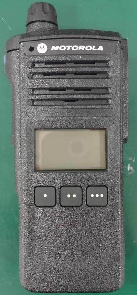
Click to zoom
Application Details
- Equipment Class
- TNF - Licensed Non-Broadcast Transmitter Held to Face
- Date of Grant
- Mar 24, 2014
- Application Purpose
- Original Equipment
- Date of Application
- Mar 24, 2014
- Equipment Note
- Portable 2-Way Radio
- Frequency Range
- 406.10000000 - 470.00000000
- Company
- Motorola Solutions, Inc.
- Country
- United States
Documents & Files
Document Text
Text extracted from the exhibit documents filed with the FCC. Open a document above to read the original.
Users Manual
APX 1000 User Guide Model 3 MN000255A01-A APX_4000_M3.book Page 1 Thur sday, March 13, 2014 10:59 AM APX_4000_M3.book Page 2 Thur sday, March 13, 2014 10:59 AM English mASTRO ® APX™ 1000 Series Digital Portable RadiosQuick Reference Card RF Energy Exposure and Product Safety Guide for Portable Two-Way Radios ATTENTION! This radio is restricted to Occupational use only. Before using the radio, read the RF Energy Exposure and Product Safety Guide for Portable Two-Way Radios which contains important operating instructions for safe usage and RF energy awareness and control for Compliance with applicable standards and Regulations. Radio Controls Radio On/OffZones and Channels Receiving and TransmittingSending an Emergency Alarm * Default emergency button press timer is set to 1 second. This timer is programmable, see page 66 in the user guide for details.To exit emergency at any time, press and hold the Emergency button. Battery Multi Function Knob (MFK):Primary Feature:_________________Secondary Feature:_________________ Accessory Connector Microphone Antenna • On – Press and hold the MFK until the display lights up. • Off – Press and hold the MFK until you see Power off? , then press Menu Select button below Yes . • Zone – Zone scroll to desired zone. • Channel – Channel scroll to desired channel. Data Feature Button Side Button 1__________ Side Button 2__________PTT Button MicrophoneTop Lightbar IndicatorTop Side (Select) Button__________ Main Speaker Main Display Top (Orange) Button___________LED Keypad Menu Select Buttons 4-Way Navigation Button Home Button 1 Select zone/channel. 2 Listen for a transmission.ORPress and hold Volume Set button. ORPress Monitor button and listen for activity. 3 Adjust volume, if necessary. 4 Press the PTT button to transmit; release to receive. 1 Press and hold the Emergency button*. 2 The display shows Emergency and the current zone/channel. Radio sounds a short, medium-pitched tone, and the LED blinks red momentarily. 3 When acknowledgment is received, you hear four beeps; alarm ends; and radio exits emergency. *PMLN6813A* PMLN6813A MOTOROLA, MOTO, MOTOROLA SOLUTIONS and the Stylized M logo are trademarks or registered trademarks of Motorola Trademark Holdin gs, LLC and are used under license. All other trademarks are the property of th eir respective owners. © 2014 by Motorola Solutions, Inc. All Rights Reserved. 03/14 1303 East Algonquin Road, Schaumburg, Illinois 60196, U.S.A. APX_4000_M3.book Page 3 Thur sday, March 13, 2014 10:59 AM English Sending an Emergency Call To exit emergency at any time, press and hold the Emergency button. Sending a Silent Emergency Call To exit emergency at any time, press and hold the Emergency button. Display Status Icons 1 Press the Emergency button. 2 Press and hold the PTT button. Speak clearly into the microphone. 3 Release the PTT button to end call. 4 Press and hold Emergency button to exit emergency. 1 Press the Emergency button. 2 The display does not change; the LED does not light up, and there is no tone. 3 Silent emergency c ontinues until you: Press and hold the Emergency button to exit emergency state.ORPress and release the PTT button to exit the Silent Emergency Alarm mode and enter regular dispatch or Emergency Call mode. Receiving a call or data.Transmitting a call or data. u t Blinks when the battery is low.The more stripes, the stronger the signal strength for the current site (trunking only).Direct radio to radio communication or connected through a repeater.On = Direct Off = Repeater This channel is being monitored.L = Radio is set at Low power. H = Radio is set at High power. Scanning a scan list.Blinking dot = Detects activity on the Priority-One Channel during scan. Steady dot = Detects activity on the Priority-Two Channel during scan. 8 v O M H OR . i j The vote scan feature is enabled.On = Location feature enabled, and location signal available. Off = Location feature disabled. Blinking = Location feature enabled, but location signal unavailable.On = User is currently associated with the radio. Off = User is currently not associated with the radio. Blinking = Device registration or user registration with the server failed due to an invalid username or pin.Data activity is present. k G no Menu Navigation < or > to Menu Entry. { , | , or } directly below Menu Entry to select. H to exit. U or D to scroll through sub-list. { , | , or } directly below Menu Entry to select. APX_4000_M3.book Page 4 Thur sday, March 13, 2014 10:59 AM Declaration of Conformity English i Declaration of Conformity This declaration is applicable to your radio only if your radio is labeled with the FCC logo shown below. DECLARATION OF CONFORMITYPer FCC CFR 47 Part 2 Section 2.1077(a)Responsible Party Name: Motorola Solutions, Inc.Address: 1303, East Algonquin Road, Schaumburg, Illinois 60196, U.S.A.Phone Number: 1-800-927-2744Hereby declares that the product: Model Name: APX 1000 conforms to the following regulations: FCC Part 15, subpart B, section 15.107(a), 15.107(d) and section 15.109(a) Class B Digital DeviceAs a personal computer peripheral, this device complies with Part 15 of the FC C Rules. Operation is subject to the following two conditions: 1. This device may not cause harmful interference, and 2. This device must accept any interference received, including interference that may cause undesired operation. APX_4000_M3.book Page i Thursday, March 13, 2014 10:59 AM Declaration of Conformity English ii Note: This equipment has been tested and found to comply with the li mits for a Class B digital device, pursuant to part 15 of the FCC Rules. These limits are designed to provi de reasonable protection against harmful interference in a residential installation. This equipment generates, us es and can radiate radio frequency energy and, if not installed and used in accordance with the instructions, may cause harmful interference to radio communications. However, there is no guarantee that interference wi ll not occur in…
Text truncated - open the document above for the full version.
Users Manual
English RF ENERGY EXPOSURE AND PRODUCT SAFETY GUIDE FOR PORTABLE TWO-WAY RADIOS Before using this radio, read this guide which contains important operating instructions for safe usage and RF energy awareness and control for compliance with applicable standards and regulations. Motorola Solutions, Inc. 1303 E. Algonquin Rd., Schaumburg, IL 60196, U.S.A. *NNTN7223G* NNTN7223G MOTOROLA, MOTO, MOTOROLA SOLUTIONS and the Stylized M logo are trademarks or registered trademarks of Motorola Trademark Holdings, LLC and are used under license. All other trademarks are the property of their respective owners. © 2007 – 2013 Motorola Solutions, Inc. All rights reserved. ATTENTION! *6881095C98* 6881095C98-K 6881095C98-K_SafetyP.book Page 1 Tuesday, September 3, 2013 3:56 PM 2 English RF Energy Exposure Awareness and Control Information and Operational Instructions for Occupational Use NOTICE: This radio is intended for use in occupational/controlled conditions where users have full knowledge of their exposure and can exercise control over their exposure to meet the occupational limits in FCC and International standards. This radio device is NOT authorized for general population consumer use. This two-way radio uses electromagnetic energy in the radio frequency (RF) spectrum to provide communications between two or more users over a distance. It uses radio frequency (RF) energy or radio waves to send and receive calls. RF energy is one form of electromagnetic energy. Other forms include, but are not limited to, sunlight and x-rays. RF energy, however, should not be confused with these other forms of electromagnetic energy, which when used improperly, can cause biological damage. Very high levels of x-rays, for example, can damage tissues and genetic material. Experts in science, engineering, medicine, health, and industry work with organizations to develop standards for safe exposure to RF energy. These standards provide recommended levels of RF exposure for both workers and the general public. These recommended RF exposure levels include substantial margins of protection. All Motorola two-way radios are designed, manufactured, and tested to ensure they meet government-established RF exposure levels. In addition, manufacturers also recommend specific operating instructions to users of two-way radios. These instructions are important because they inform users about RF energy exposure and provide simple procedures on how to control it. 6881095C98-K_SafetyP.book Page 2 Tuesday, September 3, 2013 3:56 PM 3 English Please refer to the following websites for more information on what RF energy exposure is and how to control your exposure to assure compliance with established RF exposure limits: http://www.fcc.gov/oet/rfsafety/rf-faqs.html www.who.int/en/ www.motorolasolutions.com/rfhealth Federal Communication Commission (FCC) Regulations When two-way radios are used as a consequence of employment, the FCC requires users to be fully aware of and able to control their exposure to meet occupational requirements. Exposure awareness can be facilitated by the use of a product label directing users to specific user awareness information. Your Motorola two-way radio has a RF Exposure Product Label. Also, your Motorola user manual, or separate safety booklet includes information and operating instructions required to control your RF exposure and to satisfy compliance requirements. Compliance with RF Exposure Standards Your Motorola two-way radio is designed and tested to comply with a number of national and International standards and guidelines (listed below) for human exposure to radio frequency electromagnetic energy. This radio complies with the IEEE (FCC) and ICNIRP exposure limits for occupational/controlled RF exposure environments at operating duty factors of up to 50% talk-50% listen and is approved for occupational use only. In terms of measuring RF energy for compliance with these exposure guidelines, your radio generates measurable RF energy only while it is transmitting (during talking), not when it is receiving (listening) or in standby mode. 6881095C98-K_SafetyP.book Page 3 Tuesday, September 3, 2013 3:56 PM 4 English NOTE:The approved batteries, supplied with this radio, are rated for a 5-5-90 duty factor (5% talk-5% listen-90% standby) even though this radio complies with FCC occupational exposure limits and may operate at duty factors of up to 50% talk. Your Motorola two-way radio complies with the following RF energy exposure standards and guidelines: • United States Federal Communications Commission (FCC), Code of Federal Regulations; 47 CFR et seq. & FCC, OET Bulletin 65 • Institute of Electrical and Electronic Engineers (IEEE) C95.1 • International Commission on Non-Ionizing Radiation Protection (ICNIRP) • Ministry of Health (Canada) Safety Code 6 & Industry Canada RSS-102 • Australian Communications Authority Radiocommunications Standard et seq. • ANATEL ANNEX to Resolution No. 303 et seq. RF Exposure Compliance and Control Guidelines and Operating Instructions for Two-Way Radio Operations To control your exposure and ensure compliance with the occupational/controlled environment exposure limits, always adhere to the following procedures. • DO NOT remove the RF Exposure Label from the device. • User awareness instructions should accompany device when transferred to other users. 6881095C98-K_SafetyP.book Page 4 Tuesday, September 3, 2013 3:56 PM 5 English Two-Way Radio Operation • Transmit no more than the rated duty factor of 50% of the time. To transmit (talk), push the Push-To-Talk (PTT) button. To receive calls, release the PTT button. The PTT button may reside on the radio itself or may be hosted on approved wired or wireless (for example, a Bluetooth enabled remote Push-to-Talk button) accessories. Transmitting 50% of the time, or less, is important because this radio generates measurable RF energy exposure only when transmitting (in terms of measuring for standards compliance). • In front…
Text truncated - open the document above for the full version.
Attestation Statements
Applicant: Motorola Solutions Inc FCC ID: AZ489FT4917 / IC: 109U-8 9FT4917 EXHIBIT 2 SHEET 1 OF 1 EXHIBIT 2 STATEMENT OF CERTIFICATION – Pursuant to 47 CRF 2.907 & 2.908 The technical data supplied with this application, having been taken under my supervision is hereby duly certified. The following is a statement of my qualifications: 1) I received an Electronic Majoring in Telecommunications Engineering degree from Multimedia University, Malaysia. 2) I have 3 years experience in developing, testing, and certifying Land Mobile Communications Products. NAME: Elaine Leong Ming Choo SIGNATURE: DATE: 27 th February 2014 POSITION: Electrical Engineer 3) I hereby certify that the above application was prepared under my direction and that to the best of my knowledge and belief, the facts set forth in the application and accompanying technical data are true and correct. NAME: Peter Keh SIGNATURE: DATE: 27 th February 2014 POSITION: Engineering Section Manager
Cover Letter(s)
FCC ID: AZ489FT4917 Motorola Solutions Inc. Exhibit 13a 8000 West Sunrise Boulevard, Fort Lauderdale, Florida 33322 Date: March 11, 2014 Office of Engineering and Technology Laboratory Division Equipment Authorization Branch Federal Communications Commission Laboratory 7435 Oakland Mills Road Columbia, MD 21046 Subject: Application for Certification of Transmitter with FCC ID: AZ489FT4917 Dear Sir or Madam: Motorola Solutions Inc, 8000 West Sunrise Boulevard, Fort Lauderdale, Florida, herein submits application for Certification of the subject transmitter. This transmitter is intended for use in a Portable Radio environment with capabilities for clear and coded communications with a variable transmit power operating within the following frequency ranges: 380 - 470 MHz: 1 – 5.0 Watts (Nominal) We are requesting Certification under part 90.203(j)(4) of the Commission’s Rules to allow operation of this equipment. The subject transmitter complies with Section 90.203 of the Rules in that the operator cannot directly program transmit frequencies using the unit's normally accessible external controls. A complete application for the aforementioned modifications is enclosed. Please contact me if you require any additional information. Sincerely, Kim Uong Manager, Regulatory Compliance Tel: (954) 723-5422 E-mail: [email protected]
Cover Letter(s)
FCC ID: AZ489FT4917 Motorola Solutions Inc. Exhibit 13b 8000 West Sunrise Boulevard, Fort Lauderdale, Florida 33322 CONFIDENTIALITY REQUESTED Date: March 11, 2014 Office of Engineering and Technology Laboratory Division Equipment Authorization Branch Federal Communications Commission Laboratory 7435 Oakland Mills Road Columbia, MD 21046 Subject: Application for Certification of Transmitter with FCC ID: AZ489FT4917. Dear Sir or Madam: Motorola Solutions Inc, 8000 West Sunrise Boulevard, Fort Lauderdale, Florida, is requesting for the following Exhibits not to be made routinely available for public inspection: Exhibit 4 (Circuit Descriptions), Exhibit 5 (Schematic Diagrams), Exhibit 10 (Parts List and Tune Up Procedures), Exhibit 12 (Transmitter Description) Motorola considers the information in these exhibits to be classified as trade secrets, pursuant to 47 CFR Sections 0.457(d), 0.459 and 552(b)(4) of the Freedom of Information Act. Please mark Exhibits 4, 5, 10 and 12 as “Confidential.” Please contact me if you require any additional information. Sincerely, Kim Uong Manager, Regulatory Compliance Tel: (954) 723-5422 Email: [email protected]
Cover Letter(s)
FCC ID: AZ489FT4917 Motorola Solutions Inc. Exhibit 13c 8000 West Sunrise Boulevard, Fort Lauderdale, Florida 33322 Date: March 11, 2014 Office of Engineering and Technology Laboratory Division Equipment Authorization Branch Federal Communications Commission Laboratory 7435 Oakland Mills Road Columbia, MD 21046 Subject: Extended Frequencies Justification for FCC ID: AZ489FT4917 Dear sir or Madam: The APX1000 Portable 2-Way radio was designed to operate in the frequency band 380-470 MHz. To aid equipment authorization in other countries which accept the United States FCC Grant for Certification, Motorola is requesting that the FCC lists the frequencies 380-470 MHz under FCC Rule Parts 90 on the FCC Grant. For the FCC’s Rule Parts 90 applications, this radio is used in systems by Federal and Public Safety agencies including Police, Fire, and Emergency Medical Services, etc. as indicated in the table below. Equipment programming is the responsibility of Authorized Service Personnel. Also, the radio complies with 47 CFR Part 90.203(e), in that the operator cannot directly program the transmit frequencies using the normally accessible external controls. Per the FCC’s KDB634817 guidance, as an alternative to listing the exact frequencies, we acknowledge that it’s a violation of the FCC Rules if this device operates on unauthorized frequencies. Frequency Range (MHz) Part 90 Federal Emission Designator Rule Part 90 380 - 406 x 11K0F3E, 8K10F1D, 8K10F1E, 8K10F1W, 16K0F3E 454 - 456* 406.1 - 454 x 11K0F3E, 8K10F1D, 8K10F1E, 8K10F1W 456 - 470 x * Canada Sincerely, Kim Uong Manager, Regulatory Compliance Email: [email protected]
External Photos
Applicant: Motorola Solutions Inc. FCC ID: AZ489FT4917 / IC: 109U-89FT4917 EXHIBIT 3 SHEET 1 OF 7 EXHIBIT 3 The following photographs are attached. Exhibit 1. Back View with Battery 3A 2. Front View with Display and Keypad. 3B 3. Back View (FCC label location). 3C 4. Side view (Right). 3D 5. Side view (Left). 3E 6. Top view. 3F 7. Bottom view. 3G Applicant: Motorola Solutions Inc. FCC ID: AZ489FT4917 / IC: 109U-89FT4917 EXHIBIT 3 SHEET 2 OF 7 Exhibit 3A - BACK VIEW WITH BATTERY Model 3 / Model 2 / Model 1.5 Applicant: Motorola Solutions Inc. FCC ID: AZ489FT4917 / IC: 109U-89FT4917 EXHIBIT 3 SHEET 3 OF 7 Exhibit 3B - FRONT VIEW Model 3 Model 2 Model 1.5 Applicant: Motorola Solutions Inc. FCC ID: AZ489FT4917 / IC: 109U-89FT4917 EXHIBIT 3 SHEET 4 OF 7 Exhibit 3C - BACK VIEW (FCC LABELS) Model 3 / Model 2 / Model 1.5 Applicant: Motorola Solutions Inc. FCC ID: AZ489FT4917 / IC: 109U-89FT4917 EXHIBIT 3 SHEET 5 OF 7 Exhibit 3D - SIDE VIEW (RIGHT) Model 3 / Model 2 / Model 1.5 Applicant: Motorola Solutions Inc. FCC ID: AZ489FT4917 / IC: 109U-89FT4917 EXHIBIT 3 SHEET 6 OF 7 Exhibit 3E - SIDE VIEW (LEFT) Model 3 / Model 2 / Model 1.5 Applicant: Motorola Solutions Inc. FCC ID: AZ489FT4917 / IC: 109U-89FT4917 EXHIBIT 3 SHEET 7 OF 7 Exhibit 3F - TOP VIEW Model 3 / Model 2 / Model 1.5 Exhibit 3G - BOTTTOM VIEW Model 3 / Model 2 / Model 1.5
ID Label/Location Info
Applicant: Motorola Solutions Inc FCC ID: AZ489FT4917 / IC: 109U-8 9FT4917 EXHIBIT 1 SHEET 1 OF 2 Identification Label LOCATION See the Attached Photograph or Sketch Top of Radio X Back of Radio Back of Radio under Belt Clip TYPE X The label is a polyester film laminate with a pressure sensitive adhesive backing. The adhesive is a permanent type acrylic with the minimum peel strength of 32 oz/inch. MARKINGS (TEXT) X See the Attached Photograph and Exhibit 3C for the actual location of the FCC label on the device. Label Attached Below. See Attached Drawing. Figure 1 : FCC IC Label for Sales model H84QDH9PW7AN (Model 3 Full keypad) Applicant: Motorola Solutions Inc FCC ID: AZ489FT4917 / IC: 109U-8 9FT4917 EXHIBIT 1 SHEET 2 OF 2 Figure 2 : FCC IC Label for Sales model H84QDF9PW6AN (Model 2 Limited Keypad) Figure 3 : FCC IC Label for Sales model H84QDD9PW5AN (Model 1.5 Three Button Keypad)
Internal Photos
Applicant: Motorola Solutions Inc. FCC ID: AZ489FT4917 / IC: 109U-8 9FT4917 EXHIBIT 9 SHEET 1 OF 6 EXHIBIT 9 Internal Photographs The following photographs are attached. Exhibit 1. RF board without & with Shields (Top). 9A 2. RF board without & with Shields (Bottom). 9B 3. Keypad Board Bottom 9C 4. Keypad Board (Top). 9D 5. RF board with chassis and housing (front side). 9E 6. RF Board with chassis and housing (back side). 9F Applicant: Motorola Solutions Inc. FCC ID: AZ489FT4917 / IC: 109U-8 9FT4917 EXHIBIT 9 SHEET 2 OF 6 EXHIBIT 9A - RF board without & with Shields (Top) Model 3 / Model 2 / Model 1.5 Applicant: Motorola Solutions Inc. FCC ID: AZ489FT4917 / IC: 109U-8 9FT4917 EXHIBIT 9 SHEET 3 OF 6 EXHIBIT 9B - RF board without & with Shields (Bottom) Model 3 / Model 2 / Model 1.5 Applicant: Motorola Solutions Inc. FCC ID: AZ489FT4917 / IC: 109U-8 9FT4917 EXHIBIT 9 SHEET 4 OF 6 EXHIBIT 9C - Keypad board (Bottom) Model 3 / Model 2 / Model 1.5 EXHIBIT 9D - Keypad Board (Top) Model 3 Model 2 Model 1.5 Applicant: Motorola Solutions Inc. FCC ID: AZ489FT4917 / IC: 109U-8 9FT4917 EXHIBIT 9 SHEET 5 OF 6 EXHIBIT 9E - RF board with chassis and housing (front side) Model 3 Model 2 Model 1.5 Applicant: Motorola Solutions Inc. FCC ID: AZ489FT4917 / IC: 109U-8 9FT4917 EXHIBIT 9 SHEET 6 OF 6 EXHIBIT 9F - Chassis and Housing (back side) Model 3 / Model 2 / Model 1.5
RF Exposure Info
FCC ID: AZ489FT4917/IC: 109U-89FT4917 SR11909 Motorola Solutions EME Inc. Form-SAR-Rpt-Rev. 13.2 Page 1 of 50 TESTING CERT # 2518.01 DECLARATION OF COMPLIANCE SAR ASSESSMENT Part 1 of 2 Motorola Solutions Inc. EME Test Laboratory 8000 West Sunrise Blvd Fort Lauderdale, FL. 33322 Date of Report: 03/13/2014 Report Revision: B Report ID: SR11909_H84QDH9PW7AN Rev B 140313 Responsible Engineer: Mac Elliott (Principle Staff Engineer) Report Author: Mac Elliott (Principle Staff Engineer) Date/s Tested: 12/21/13 – 12/22/13; 1/08/14 Manufacturer/Location: Motorola Solutions Inc, Penang Sector/Group/Div.: AESS – Astro Engineering Subscriber Solutions Date submitted for test: 12/17/13 DUT Description: Handheld Portable - 380-470MHz, 5.0W rated power, 6.25KHz/12.5KHz/25KHz, Capable of FM and TDMA transmission Test TX mode(s): CW (PTT) Max. Power output: 5.7W (380-470MHz) Nominal Power: 5.0W (380-470MHz) Tx Frequency Bands: 380MHz-470MHz Signaling type: FM, TDMA Model(s) Tested: H84QDH9PW7AN (MUE4386) Model(s) Certified: H84QDH9PW7AN (MUE4386) Serial Number(s): 837TPX0078 & 837TPX0064 Classification: Occupational/Controlled FCC ID: AZ489FT4917; Rule Part 90 (406.1-470MHz) This report contains results that are immaterial for FCC equipment approval, which are clearly identified. Only apply when applicable. IC: 109U-89FT4917 (406.1-430MHz & 450-470MHz) The test results clearly demonstrate compliance with FCC Occupational/Controlled RF Exposure limits of 8 W/kg averaged over 1 gram per the requirements of 47 CFR 2.1093(d). The 10 grams result is not applicable to FCC filing. The test results clearly demonstrate compliance with ICNIRP (1998) Guidelines for limiting exposure in time-varying electric, magnetic, and electromagnetic fields (up to 300 GHz), Health Physics 74, 494-522 RF Exposure limits of 10 W/kg averaged over 10grams of contiguous tissue. Based on the information and the testing results provided herein, the undersigned certifies that when used as stated in the operating instructions supplied, said product complies with the national and international reference standards and guidelines listed in section 3.0 of this report. This report shall not be reproduced without written approval from an officially designated representative of the Motorola Solutions Inc EME Laboratory. I attest to the accuracy of the data and assume full responsibility for the completeness of these measurements. This reporting format is consistent with the suggested guidelines of the TIA TSB-150 December 2004. The results and statements contained in this report pertain only to the device(s) evaluated. Deanna Zakharia EMS EME Lab Senior Resource Manager, Laboratory Director Approval Date: 3/13/2014 Certification Date: 3/5/2014 Certification No.: L1140301P FCC ID: AZ489FT4917/IC: 109U-89FT4917 SR11909 Motorola Solutions EME Inc. Form-SAR-Rpt-Rev. 13.2 Page 2 of 50 Part 1 of 2 1.0 Introduction ................................................................................................................................. 4 2.0 FCC SAR Summary .................................................................................................................... 4 3.0 Abbreviations / Definitions ......................................................................................................... 4 4.0 Referenced Standards and Guidelines ........................................................................................ 5 5.0 SAR Limits ................................................................................................................................. 6 6.0 Description of Device Under Test (DUT) .................................................................................. 6 7.0 Optional Accessories and Test Criteria....................................................................................... 7 7.1 Antennas ......................................................................................................................... 7 7.2 Battery ............................................................................................................................. 7 7.3 Body worn Accessories ................................................................................................... 7 7.4 Audio Accessories .......................................................................................................... 8 8.0 Description of Test System ....................................................................................................... 10 8.1 Descriptions of Robotics/Probes/Readout Electronics ................................................. 10 8.2 Description of Phantom(s) ............................................................................................ 11 8.3 Description of Simulated Tissue ................................................................................... 11 9.0 Additional Test Equipment ....................................................................................................... 12 10.0 SAR Measurement System Validation and Verification .......................................................... 12 10.1 System Validation ......................................................................................................... 12 10.2 System Verification ...................................................................................................... 13 10.3 Equivalent Tissue Test Results ..................................................................................... 13 11.0 Environmental Test Conditions ................................................................................................ 14 12.0 DUT Test Setup and Methodology ........................................................................................... 14 12.1 Measurements ............................................................................................................... 14 12.2 DUT Configuration(s) .............................................…
Text truncated - open the document above for the full version.
RF Exposure Info
FCC ID: AZ489FT4917/IC: 109U-89FT4917 SR11909 Motorola Solutions Inc. EME Form-SAR-Rpt-Rev. 13.2 Page 1 of 19 TESTING CERT # 2518.01 DECLARATION OF COMPLIANCE SAR ASSESSMENT Part 2 of 2 Motorola Solutions Inc. EME Test Laboratory 8000 West Sunrise Blvd Fort Lauderdale, FL. 33322 Date of Report: 03/13/2014 Report Revision: B Report ID: SR11909_H84QDH9PW7AN Rev B 140313 Responsible Engineer: Mac Elliott (Principle Staff Engineer) Report Author: Mac Elliott (Principle Staff Engineer) Date/s Tested: 12/21/13 – 12/22/13; 1/08/14 Manufacturer/Location: Motorola Solutions Inc., Penang Sector/Group/Div.: AESS – Astro Engineering Subscriber Solutions Date submitted for test: 12/17/13 DUT Description: Handheld Portable - 380-470MHz, 5.0W rated power, 6.25KHz/12.5KHz/25KHz, Capable of FM and TDMA transmission Test TX mode(s): CW (PTT) Max. Power output: 5.7W (380-470MHz) Nominal Power: 5.0W (380-470MHz) Tx Frequency Bands: 380MHz-470MHz Signaling type: FM, TDMA Model(s) Tested: H84QDH9PW7AN (MUE4386) Model(s) Certified: H84QDH9PW7AN (MUE4386) Serial Number(s): 837TPX0078 & 837TPX0064 Classification: Occupational/Controlled FCC ID: AZ489FT4917; Rule Part 90 (406.1-470MHz) This report contains results that are immaterial for FCC equipment approval, which are clearly identified. Only apply when applicable. IC: 109U-89FT4917 (406.1-430MHz & 450-470MHz) The test results clearly demonstrate compliance with FCC Occupational/Controlled RF Exposure limits of 8 W/kg averaged over 1 gram per the requirements of 47 CFR 2.1093(d). The 10 grams result is not applicable to FCC filing. The test results clearly demonstrate compliance with ICNIRP (1998) Guidelines for limiting exposure in time-varying electric, magnetic, and electromagnetic fields (up to 300 GHz), Health Physics 74, 494-522 RF Exposure limits of 10 W/kg averaged over 10grams of contiguous tissue. Based on the information and the testing results provided herein, the undersigned certifies that when used as stated in the operating instructions supplied, said product complies with the national and international reference standards and guidelines listed in section 3.0 of this report. This report shall not be reproduced without written approval from an officially designated representative of the Motorola Solutions Inc EME Laboratory. I attest to the accuracy of the data and assume full responsibility for the completeness of these measurements. This reporting format is consistent with the suggested guidelines of the TIA TSB-150 December 2004. The results and statements contained in this report pertain only to the device(s) evaluated. Deanna Zakharia EMS EME Lab Senior Resource Manager, Laboratory Director Approval Date: 3/13/2014 Certification Date: 3/5/2014 Certification No.: L1140301P FCC ID: AZ489FT4917/IC: 109U-89FT4917 SR11909 Motorola Solutions Inc. EME Form-SAR-Rpt-Rev. 13.2 Page 2 of 19 APPENDIX D System Verification Check Scans FCC ID: AZ489FT4917/IC: 109U-89FT4917 SR11909 Motorola Solutions Inc. EME Form-SAR-Rpt-Rev. 13.2 Page 3 of 19 FCC ID: AZ489FT4917/IC: 109U-89FT4917 SR11909 Motorola Solutions Inc. EME Form-SAR-Rpt-Rev. 13.2 Page 4 of 19 FCC ID: AZ489FT4917/IC: 109U-89FT4917 SR11909 Motorola Solutions Inc. EME Form-SAR-Rpt-Rev. …
Text truncated - open the document above for the full version.
Contact Information
Applicant
Arine Lee(Certification Manager)
Test Firm
Motorola Solutions Malaysia Sdn BhdSze Khian Ho
Technical Specifications
| # | Rule Parts | Frequency Range | Power Output | Emission | Tolerance |
|---|---|---|---|---|---|
| 4 | 90.210(e) | 406.1 MHz - 470 MHz | 5 W | 8K10F1W | 2 ppm |
Other Applications from Motorola Solutions, Inc.

AZ489FT4980
Sep 08, 2026Portable two way radio
Equipment Class
TNF - Licensed Non-Broadcast Transmitter Held to FaceAZ489FT4981
Aug 14, 2026Handheld Portable - TANAPA BPR 45 400-470 MHZ 4W NKP
Equipment Class
TNF - Licensed Non-Broadcast Transmitter Held to Face
AZ489FT7187
Jul 13, 2026Portable 2-Way Radio with Bluetooth, Bluetooth LE, WIFI 2.4GHz, WIFI 5GHz, LTE
Equipment Class
DSS - Part 15 Spread Spectrum TransmitterAZ499FT6031
May 11, 2026Operation Critical Wireless Earpiece PTT
Equipment Class
DSS - Part 15 Spread Spectrum Transmitter
AZ499FT5879
Dec 19, 20252-way Portable Radio with BT, BTLE, WIFI, NFC and LTE
Equipment Class
DSS - Part 15 Spread Spectrum Transmitter