AZ489FT4959Consumer Radio 462-467MHz and Weather Band receiver
Motorola Solutions, Inc.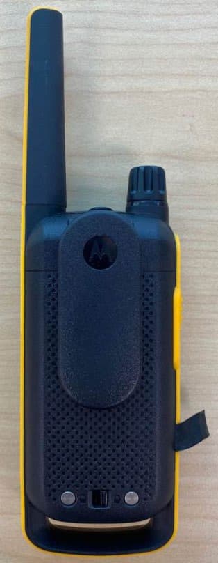
Click to zoom
Application Details
- Equipment Class
- CXX - Communications Rcvr for use w/ licensed Tx and CBs
- Date of Grant
- Apr 07, 2020
- Application Purpose
- Original Equipment
- Date of Application
- Apr 06, 2020
- Equipment Note
- Consumer Radio 462-467MHz and Weather Band receiver
- Frequency Range
- 161.65000000 - 162.55000000
- Company
- Motorola Solutions, Inc.
- Country
- United States
Documents & Files
Document Text
Text extracted from the exhibit documents filed with the FCC. Open a document above to read the original.
Users Manual
en-US fr-CA es-LA pt-BR TALKABOUT ® TWO-WAY RADIO T47X SERIES 1 English SAFETY AND GENERAL INFORMATIONCautionBefore using this radio, read this booklet which contains important operating instructions. For information on product details, brochures, user manuals and approved accessories. Please refer to www.motorolasolutions.com . Compliance with RF Exposure StandardsNational and international regulations require manufacturers to comply with the RF energy exposure limits for portable two-way radios before they can be marketed. Your Motorola Solutions two-way radio is designed, manufactured, and tested to comply with all applicable national and international regulations for human exposure to radio frequency electromagnetic energy.RF Energy Exposure Awareness and Control Information and Operational Instructions for General Population and Uncontrolled Environment UseFor more information on what RF energy exposure is, see the following websites:• https://www.fcc.gov/ • http://www.who.int/peh-emf/project/en/ • http://www.ic.gc.ca/eic/site/smt-gst.nsf/eng/sf11467.html • http://www.ic.gc.ca/eic/site/smt-gst.nsf/eng/sf01904.html For additional information, see https://www.motorolasolutions.com/en_us/about/company-overview/corporate-responsibility/governance-and-policies.html Operating Instructions• Transmit no more than 50% of the time. To transmit (talk), press the Push-To-Talk ( PTT ) button. To receive calls, release the PTT button. • Hold the radio in a vertical position in front of the face with the microphone (and other parts of the radio including the antenna) at least 1 in. (2.5 cm) away from the nose or lips. Antenna should be kept away from the eye. • When worn on the body, always place the radio in a Motorola Solutions-approved clip, holder, holster, case, or body harness for this product. • DO NOT hold the antenna when the radio is transmitting.• DO NOT use any portable radio that has a damaged antenna. If a damaged antenna comes into contact with your skin, a minor burn can result. • To ensure continued compliance with applicable RF exposure limits, use only Motorola Solutions-approved, supplied or replacement antennas, batteries, and accessories. • For a list of Motorola Solutions-approved accessories please refer to your user manual or visit www.motorolasolutions.com 2 English Acoustic SafetyExposure to loud noises from any source for extended periods of time may temporarily or permanently affect your hearing. The louder the volume of the radio, the sooner your hearing will be affected. Hearing damage from loud noise is sometimes undetectable at first, and can have a cumulative effect.To protect your hearing, follow these precautions:• Use the lowest volume necessary to do your job.• Turn up the volume only if you are in noisy surroundings.• Turn down the volume before putting on a headset or headphones. • Limit the amount of time you use a headset or headphones at high volume. • When using the radio without a headset or headphones, do not place the speaker of the radio directly against your ear. Medical DevicesIf you use a personal medical device, such as a pacemaker or hearing aid, consult the manufacturer of your device to determine if it is adequately shielded from RF energy. Your physician may be able to assist you in obtaining this information.Holsters Incorporating MagnetsSome Motorola Solutions holsters incorporate strong, neodymium magnets. If you use a personal medical device, such as a pacemaker or hearing aid, consult the manufacturer of your device to determine if it can be used in close proximity to magnets. Your physician may be able to assist you in obtaining this information. Also be aware that magnets can damage other products, including cell phones, computers, hard drives, and other electronic devices, as well as credit cards and magnetic media. Keep the holster away from any mechanical device that could be affected by a magnetic field. Consult the manufacturer of your product to determine if your device or product can be used in close proximity to magnets. Operational WarningsThe following explains the operational warnings:For Vehicle With Air Bags Warning:• Refer to vehicle manufacturer's manual prior to installation of electronic equipment to avoid interference with air bag wiring. • DO NOT place a portable radio in the area over an air bag or in the air bag deployment area. Air bags inflate with great force. If a portable radio is placed in the air bag deployment area and the air bag inflates, the radio may be propelled with great force and cause serious injury to occupants of the vehicle. ! W A R N I N G ! 3 English Potentially Explosive Atmospheres Blasting Caps and Blasting Areas Batteries • Charge your battery using the approved Motorola Solutions charger. • Use the battery in accordance with its water and/or dust Ingress Protection (IP) rating. • DO NOT discard your battery into a fire.• DO NOT replace the battery in any area labeled “Hazardous Atmosphere”. • DO NOT disassemble, crush, puncture, shred, or otherwise attempt to change the form of your battery. • DO NOT dry a wet or damp battery with an appliance or heat source, such as a hair dryer or microwave oven. • DO NOT allow conductive material such as jewelry, keys, or beaded chains to touch exposed battery terminals. • Do not dispose of batteries with household waste. Warning:• Use of a radio that is not intrinsically safe in a potentially explosive atmosphere could result in a serious injury, or death. You should only use a certified Intrinsically Safe radio in potentially explosive atmospheres. • Explosive atmospheres refer to hazard classified locations that may contain hazardous gas, vapors, dusts, such as fueling areas below decks on boats, fuel, or chemical transferor storage facilities, and areas where the air contains chemicals or particles such as grain, dust, or metal powders. Areas with potentially explosive atmospheres are often, but not always, posted. • Turn off your radio prior to en…
Text truncated - open the document above for the full version.
Cover Letter(s)
Applicant: Motorola Solutions Inc FCC ID: AZ489FT4959 / IC: 109U-89FT4959 EXHIBIT 2 SHEET 1 OF 1 EXHIBIT 2 Statement of Certification (Pursuant to FCC Part 2.907, 2.908 and RSP 100 Sec 4) 2.1 Statement of Certification Transceiver type described herein (AZ489FT4959/109U-89FT4959) is in compliance with all applicable parts of the FCC rules and ISED RSS standards. Each unit manufactured, imported, or marketed will conform to the samples tested herein, within the statistical variations that can be expected due to high volume production and test measurement error. NAME: Alyssa Khoo SIGNATURE: DATE: 16-Mar-20 TITLE: Engineering Project Lead
Cover Letter(s)
FCC ID: AZ489FT4959 ___________________________________________________________________________________________________________ Motorola Solutions Malaysia Sdn Bhd, Plot 2A, Medan Bayan Lepas, Mukim 12 SWD, 11900 Bayan Lepas, Penang, Malaysia EXHIBIT 13A Date: April 6, 2020 Office of Engineering and Technology Laboratory Division Equipment Authorization Branch Federal Communications Commission Laboratory 7435 Oakland Mills Road Columbia, MD 21046 Subject: Application for Certification of Transmitter with FCC ID: AZ489FT4959 Dear Sir/Madam, Motorola Solutions Malaysia Sdn Bhd herein submits application for Certification of the subject transmitter. This transmitter is intended for use in a portable radio application with capabilities for clear and coded communications with a variable transmit power operating within the following frequency ranges: Product Name Model Numbers Description Frequency Range RF Power Talkabout Two- Way Radio T47X Series (T470/ T475) T47X T470 FRS CONSUMER RADIO 462- 467MHZ YELLOW T475 FRS CONSUMER RADIO 462- 467MHZ YELLOW FRS: 462.5625 – 462.7125MHz (Chl 1-7), 467.5625 – 467.7125MHz (Chl 8-14), 462.5500 – 462.7250MHz (Chl 15-22) FRS: Chl 1-7, Chl 15-22 ERP Low: 0.41W, Max: 0.5W Conducted Low: 0.46W, Max:0.54W ERP Rated: 1.94W, Max: 2W Conducted Rated: 1.9W, Max: 2.1W Chl 8-14 ERP Rated: 0.41W, Max: 0.5W Conducted Rated: 0.46W, Max:0.54W NOAA: 161.65 – 162.55 MHz Rx Only NOAA is short form of National Oceanic and Atmospheric Administration. It is a national weather service in US. We are requesting certification under Part(s) of the Commission’s Rules listed above to allow operation of this equipment. The transmitter is intended for work related general populations under Part 95 of the FCC rules. The subject transmitter complies with Section 95.337 and 95.363 of the Rules in that the operator cannot directly program transmit frequencies using the unit's normally accessible external controls. A complete Certification application is enclosed. If you require any additional information, please contact me at +604- 224 0258 Sincerely, Arine Lee FCC/IC Certification Manager E-mail: [email protected]
Cover Letter(s)
FCC ID: AZ489FT4959 ___________________________________________________________________________________________________________ Motorola Solutions Malaysia Sdn Bhd, Plot 2A, Medan Bayan Lepas, Mukim 12 SWD, 11900 Bayan Lepas, Penang, Malaysia EXHIBIT 13B CONFIDENTIALITY REQUEST April 6, 2020 Office of Engineering and Technology Laboratory Division Equipment Authorization Branch FCC Laboratory 7435 Oakland Mills Road Columbia, MD 21046 Subject: Confidentiality Request for Transmitter with FCC ID: AZ489FT4959 Dear Sir / Madam, Motorola Solutions Malaysia Sdn Bhd is requesting that Exhibit 4 (Circuit Descriptions), Exhibit 5 (Schematic Diagrams), Exhibit 10 (Parts List and Tune Up Procedures), and Exhibit 12 (Operational Description) not be made routinely available for public inspection. Motorola Solutions considers the information in these exhibits to be classified as trade secrets, pursuant to 47 CFR Section 0.457(d), 0.459 and Section 552(b)(4) of the Freedom of Information Act. Please mark Exhibits 4, 5, 10, and 12 as “Confidential.” Please contact me if you require any additional information. Sincerely, Arine Lee FCC/IC Certification Manager E-mail: [email protected]
Cover Letter(s)
____________________________________________________________________________ Motorola Solutions Inc, 8000 West Sunrise Boulevard, Fort Lauderdale, Florida 33322 Certification Department TIMCO Engineering, Inc 849 NW State Road 45, Newberry, Florida 32669, USA Date: 6 April 2020 Subject: Application Authorization for FCC/IC filing To Whom It May Concern: I hereby authorize Arine Lee to apply, on my behalf, the application for the following FCC/IC ID: FCC/IC ID: AZ489FT4959 / 109U-89FT4959 Please contact me if there are any questions or issues. Regards, Deanna Zakharia Regulatory Compliance Manager Tel: (954) 723 4707 Email: [email protected]
External Photos
Applicant: Motorola Solutions Inc FCC ID: AZ489FT4959 / IC: 109U-89FT4959 EXHIBIT 3 SHEET 1 OF 7 EXHIBIT 3 EXTERNAL PHOTOGRAPHS (Pursuant to FCC Part 2.1033(b)(7) and 2.1033(c)(12) and RSP 100 Annex C) The following photographs are attached. Exhibit 1. T47X Series Front View 3A 2. T47X Series Back View with Battery Cover & Belt Clip 3B 3. T47X Series Back View (FCC/IC label location) 3C 4. T47X Series Side View (Right) 3D 5. T47X Series Side View (Left) 3E 6. T47X Series Top View 3F 7. T47X Series Bottom View 3G Applicant: Motorola Solutions Inc FCC ID: AZ489FT4959 / IC: 109U-89FT4959 EXHIBIT 3 SHEET 2 OF 7 Exhibit 3A : T47X Series Front View T470 and T475 Applicant: Motorola Solutions Inc FCC ID: AZ489FT4959 / IC: 109U-89FT4959 EXHIBIT 3 SHEET 3 OF 7 Exhibit 3B : T47X Series Back View with Battery Cover & Belt Clip T470 and T475 Applicant: Motorola Solutions Inc FCC ID: AZ489FT4959 / IC: 109U-89FT4959 EXHIBIT 3 SHEET 4 OF 7 Exhibit 3C : T47X Series Back View (FCC/IC label location) T470 and T475 Applicant: Motorola Solutions Inc FCC ID: AZ489FT4959 / IC: 109U-89FT4959 EXHIBIT 3 SHEET 5 OF 7 Exhibit 3D : T47X Series Side View (Right) T470 and T475 Applicant: Motorola Solutions Inc FCC ID: AZ489FT4959 / IC: 109U-89FT4959 EXHIBIT 3 SHEET 6 OF 7 Exhibit 3E : T47X Series Side View (Left) T470 and T475 Applicant: Motorola Solutions Inc FCC ID: AZ489FT4959 / IC: 109U-89FT4959 EXHIBIT 3 SHEET 7 OF 7 Exhibit 3F : T47X Series Top View T470 and T475 Exhibit 3G : T47X Series Bottom View T470 and T475 *** END ***
ID Label/Location Info
Applicant: Motorola Solutions Inc FCC ID: AZ489FT4959/ IC: 109U-89FT4959 EXHIBIT 1 SHEET 1 OF 2 EXHIBIT 1 IDENTIFICATION LABEL (Pursuant to FCC Part 2.1033(c)(11), 2.1033(b)(7) and RSP 100 Annex C and Sec 3) LOCATION See the Attached Photograph or Sketch _____ Bottom of Radio Top of Radio _____ Back of Radio Back of Radio under Belt Clip __X__ Battery Compartment TYPE __X__ The label is a PP film laminate with a pressure sensitive adhesive backing. The adhesive is a permanent type acrylic with the minimum peel strength of 40 oz/inch. MARKINGS (TEXT) __X__ See the Attached Photograph and Exhibit 3 for the actual location of the FCC/IC label on the device. __X__ Label Attached Below. _____ See Attached Drawing. Applicant: Motorola Solutions Inc FCC ID: AZ489FT4959/ IC: 109U-89FT4959 EXHIBIT 1 SHEET 2 OF 2 T47X Series FCC/IC Label Figure 1: FCC/IC Label for T470 Figure 2: FCC/IC Label for T475 *** END ***
Internal Photos
Applicant: Motorola Solutions Inc. FCC ID: AZ489FT4959 / IC: 109U-89FT4959 Exhibit 9 Page | 1 EXHIBIT 9 Internal Photographs (Pursuant to FCC Part 2.1033(b)(7), 2.1033(c)(12) and RSP 100 Annex C) The following photographs are attached. Exhibit 1. RF board with Shields (Top) 9A 2. RF board without Shields (Top) 9B 3. RF board with Shields (Bottom) 9C 4. RF board without Shields (Bottom) 9D 5. RF boards with chassis and housing (Front Side) 9E 6. Chassis and housing (Back Side) 9F 7. Exploded View of Radio 9G Applicant: Motorola Solutions Inc. FCC ID: AZ489FT4959 / IC: 109U-89FT4959 Exhibit 9 Page | 2 Exhibit 9A : RF board with Shields (Top) T470 and T475 Applicant: Motorola Solutions Inc. FCC ID: AZ489FT4959 / IC: 109U-89FT4959 Exhibit 9 Page | 3 Exhibit 9B : RF board without Shields (Top) T470 and T475 Applicant: Motorola Solutions Inc. FCC ID: AZ489FT4959 / IC: 109U-89FT4959 Exhibit 9 Page | 4 Exhibit 9C : RF board with Shields (Bottom) T470 and T475 Applicant: Motorola Solutions Inc. FCC ID: AZ489FT4959 / IC: 109U-89FT4959 Exhibit 9 Page | 5 Exhibit 9D : RF board without Shields (Bottom) T470 and T475 Applicant: Motorola Solutions Inc. FCC ID: AZ489FT4959 / IC: 109U-89FT4959 Exhibit 9 Page | 6 Exhibit 9E : RF boards with chassis and housing for (Front Side) T470 and T475 Applicant: Motorola Solutions Inc. FCC ID: AZ489FT4959 / IC: 109U-89FT4959 Exhibit 9 Page | 7 Exhibit 9F : Chassis and housing (Back Side) T470 and T475 Applicant: Motorola Solutions Inc. FCC ID: AZ489FT4959 / IC: 109U-89FT4959 Exhibit 9 Page | 8 Exhibit 9G : Exploded View of Radio T47X Series *** END ***
Test Report
Report Template Document Number : FCD-0085 Report Template Revision Number : Rev. K Report ID: 20002-EMC-00010 FCC ID: AZ489FT4959 IC: 109U-89FT4959 1 _________ MOTOROLA PENANG ADV. COMM. LABORATORY FCC / ISED TEST REPORT Motorola Solutions Malaysia SDN BHD, Report Revision : Rev.A Plot 2A, Medan Bayan Lepas, Mukim 12 S.W.D, 11900 Bayan Lepas, Penang, Malaysia. Date/s Tested : 14-January-2020 Manufacturer : MOTOROLA SOLUTIONS MALAYSIA SDN BHD Manufacturer Address : PLOT 2A, MEDAN BAYAN LEPAS MUKIM 12, S.W.D 11900 BAYAN LEPAS PENANG, MALAYSIA Requestor : KHOO PHAIK HUN Product Type : Portable Model Number : T47X Frequency Band : 161.650MHz - 162.550MHz (Weather Frequency) Firmware Version : V1.110 Max Output Power : 0.5W ERP / 2W ERP Applicant Name : Motorola Solutions Inc ISED Registrations FCC Registrations : : MY0001 461337 The equipment was tested accordance to the requirement listed below: FCC 47 CFR Part 15B / IC RSS-GEN PASS This report shall not be reproduced without written approval from an officially designated representative of the Motorola Penang Adv. Comm. Laboratory. The results and statements contained in this report pertain only to the device(s) evaluated. Prepared By: Approved By: Mohd Helmy Shamsuddin Soon Oi May Technician Responsible Engineer Report Template Document Number : FCD-0085 Report Template Revision Number : Rev. K Report ID: 20002-EMC-00010 FCC ID: AZ489FT4959 IC: 109U-89FT4959 2 Table of Contents 1.0. General Information ................................................................................................................................. 3 2.0. Summary of Test Results ......................................................................................................................... 3 3.0. Measurement Uncertainty ........................................................................................................................ 4 4.0. Equipment List ......................................................................................................................................... 5 5.0. Test Condition.......................................................................................................................................... 7 5.1 Receiver Test Conditions .................................................................................................................. 7 6.0. Receiver Test Parameters ........................................................................................................................ 8 6.1. Conducted Spurious Output Power ......................................................................................................... 8 6.1.1. Test Setup ................................................................................................................................ 8 6.1.2. Test Result ..................................................................................................................................... 8 6.1.3. Test Limit ............................................................................................................................................. 8 6.2. Radiated Spurious Output Power ............................................................................................................. 9 6.2.1. Test Setup ................................................................................................................................ 9 6.2.2. Test Result ................................................................................................................................... 10 6.2.3. Test Limit ........................................................................................................................................... 14 6.3. AC Power Line Conducted Spur Emissions .......................................................................................... 15 6.3.1. Test Setup .............................................................................................................................. 15 6.3.2. Test Result ................................................................................................................................... 16 6.3.3. Test Limits................................................................................................................................... 16 7.0. Appendix: Test Setup Photo .................................................................................................................. 17 7.1. Conducted Spur Emission ATE Station Setup ..................................................................................................... 17 7.2. Radiated Spur Emission Station Setup .................................................................................................................. 17 7.3. AC Power Line Conducted Emission Station Setup .......................................................................................... 17 7.4. Photographs – EUT ................................................................................................................................ 18 REVISION HISTORY Revision History Description Date Originator Rev. A Initial Report 6-February-2020 Mohd Helmy Shamsuddin Report Template Document Number : FCD-0085 Report Template Revision Number : Rev. K Report ID: 20002-EMC-00010 FCC ID: AZ489FT4959 IC: 109U-89FT4959 3 1.0. General Information EUT Description: Technologies T470 FRS CONSUMER RADIOS 462-467MHZ, 0.5W-2W Modulation Type Analog The EUT contains following accessory devices and data cable: Item Brand Model or P/N 1300MAH 3XAA NIMH RECHARGEABLE BATTERY PACK MOTOROLA 1532 General Description of Applied Standards The EUT is a RF Product. According to the specifications of the manufacturer, the EUT is to comply with the requirements of the following standards: ANSI C63.4.2014 2.0. Summary of Test Results FCC General Rules Part (47CFR) IC General Rules Part Test Item Result 15.111 RSS-Gen 7.4 Conducted Spurious Output …
Text truncated - open the document above for the full version.
Test Setup Photos
Motorola Solutions Inc FCC ID: AZ489FT4959 / IC: 109U-89FT4959 EXHIBIT 7A SHEET 1 OF 8 Exhibit 7A FCC/IC Test Setup Photo – LMR/BT/BT LE/WLAN 2.4GHz Report ID : 20002-RF-00005 FCC ID : AZ489FT4959 IC : 109U-89FT4959 Model Number : T47X Table of Contents Motorola Solutions Inc FCC ID: AZ489FT4959 / IC: 109U-89FT4959 EXHIBIT 7A SHEET 2 OF 8 1.0 Pictures of Test Setup Photo for LMR/BT/BT LE/WLAN 2.4GHz ...................................................... 3 1.1. Power Line Conducted Emission Test Setup photo .................................................................... 3 1.1.1. Power Line Conducted Emission - Photo Front View .................................................... 3 1.1.2. Power Line Conducted Emission - Photo Side View ..................................................... 3 1.2. Radiated Emission test setup photo for LMR (ANSI C63.26:2015) .......................................... 4 1.2.1. Radiated Emission – Below 1GHz .................................................................................... 4 1.2.2. Radiated Emission – Above 1GHz ................................................................................... 4 1.3. Radiated Emission test setup photo for BT/BT LE/WLAN 2.4GHz (ANSI C63.10: 2013) ..... 5 1.3.1. Radiated Emission – Below 1GHz .................................................................................... 5 1.3.2. Radiated Emission – Above 1GHz ................................................................................... 5 1.4. RF Conducted Emission Test Setup photo ................................................................................... 6 1.4.1. RF Conducted Emission (LMR – ANSI C63.26:2015) ................................................... 6 1.4.2. RF Conducted Emission (BT/BT LE/WLAN 2.4GHz – ANSI C63.10: 2013) ............. 7 Motorola Solutions Inc FCC ID: AZ489FT4959 / IC: 109U-89FT4959 EXHIBIT 7A SHEET 3 OF 8 1.0 Pictures of Test Setup Photo for LMR/BT/BT LE/WLAN 2.4GHz 1.1. Power Line Conducted Emission Test Setup photo 1.1.1. Power Line Conducted Emission - Photo Front View Not applicable. Testing is not required because the radio must be turned off during charging mode 1.1.2. Power Line Conducted Emission - Photo Side View Not applicable. Testing is not required because the radio must be turned off during charging mode Motorola Solutions Inc FCC ID: AZ489FT4959 / IC: 109U-89FT4959 EXHIBIT 7A SHEET 4 OF 8 1.2. Radiated Emission test setup photo for LMR (ANSI C63.26:2015) 1.2.1. Radiated Emission – Below 1GHz 1.2.2. Radiated Emission – Above 1GHz Motorola Solutions Inc FCC ID: AZ489FT4959 / IC: 109U-89FT4959 EXHIBIT 7A SHEET 5 OF 8 1.3. Radiated Emission test setup photo for BT/BT LE/WLAN 2.4GHz (ANSI C63.10: 2013) 1.3.1. Radiated Emission – Below 1GHz Not applicable. 1.3.2. Radiated Emission – Above 1GHz Not applicable. Motorola Solutions Inc FCC ID: AZ489FT4959 / IC: 109U-89FT4959 EXHIBIT 7A SHEET 6 OF 8 1.4. RF Conducted Emission Test Setup photo 1.4.1. RF Conducted Emission (LMR – ANSI C63.26:2015) Motorola Solutions Inc FCC ID: AZ489FT4959 / IC: 109U-89FT4959 EXHIBIT 7A SHEET 7 OF 8 1.4.2. RF Conducted Emission (BT/BT LE/WLAN 2.4GHz – ANSI C63.10: 2013) Not applicable. Motorola Solutions Inc FCC ID: AZ489FT4959 / IC: 109U-89FT4959 EXHIBIT 7A SHEET 8 OF 8 END OF REPORT
Contact Information
Applicant
Deanna Zakharia(Regulatory Compliance Manager)
Test Firm
Motorola Penang Advanced Communication LaboratoryMohd Azuan Shah Yaakap
Technical Specifications
| # | Rule Parts | Frequency Range | Power Output |
|---|---|---|---|
| 1 | 15B | 161.65 MHz - 162.55 MHz | - |
Other Applications from Motorola Solutions, Inc.

AZ489FT4980
Sep 08, 2026Portable two way radio
Equipment Class
TNF - Licensed Non-Broadcast Transmitter Held to FaceAZ489FT4981
Aug 14, 2026Handheld Portable - TANAPA BPR 45 400-470 MHZ 4W NKP
Equipment Class
TNF - Licensed Non-Broadcast Transmitter Held to Face
AZ489FT7187
Jul 13, 2026Portable 2-Way Radio with Bluetooth, Bluetooth LE, WIFI 2.4GHz, WIFI 5GHz, LTE
Equipment Class
DSS - Part 15 Spread Spectrum TransmitterAZ499FT6031
May 11, 2026Operation Critical Wireless Earpiece PTT
Equipment Class
DSS - Part 15 Spread Spectrum Transmitter
AZ499FT5879
Dec 19, 20252-way Portable Radio with BT, BTLE, WIFI, NFC and LTE
Equipment Class
DSS - Part 15 Spread Spectrum Transmitter