AZ489FT5803Hand Held Portable Transmitter
Motorola Solutions, Inc.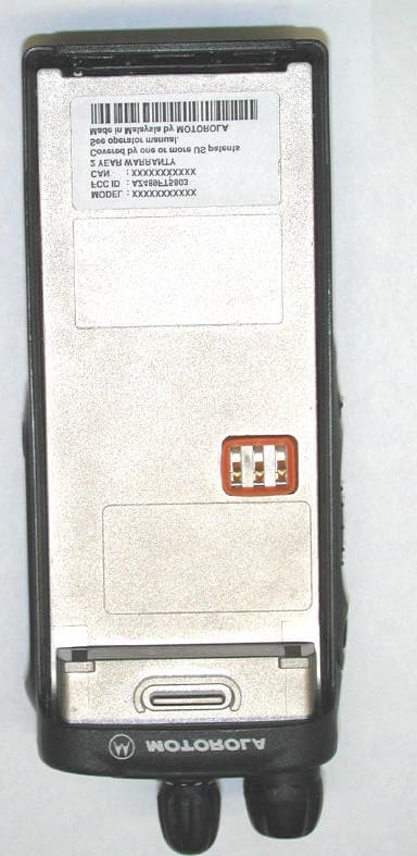
Click to zoom
Application Details
- Equipment Class
- TNF - Licensed Non-Broadcast Transmitter Held to Face
- Date of Grant
- Sep 05, 2001
- Application Purpose
- Original Equipment
- Date of Application
- Mar 22, 2001
- Equipment Note
- Hand Held Portable Transmitter
- Frequency Range
- 935.00000000 - 941.00000000
- Company
- Motorola Solutions, Inc.
- Country
- United States
Documents & Files
Document Text
Text extracted from the exhibit documents filed with the FCC. Open a document above to read the original.
Users Manual
1 English CONTENTS Contents. . . . . . . . . . . . . . . . . . . . . . . . . . . . 1 Computer Software Copyrights . . . . . . . . . . . 3 Safety . . . . . . . . . . . . . . . . . . . . . . . . . . . . . . 5 Safety and General Information . . . . . . . . . . 5Radio Frequency (RF) Operational Characteristics . . . . . . . . . . . . . . . . . . . . . . . 5Portable Radio Operation and EME Exposure . . . . . . . . . . . . . . . . . . . . . . . . . . . . 5 Two-way Radio Operation . . . . . . . . . . . . 6Body-worn Operation . . . . . . . . . . . . . . . . 6Antenna Care . . . . . . . . . . . . . . . . . . . . . . 7Approved Accessories . . . . . . . . . . . . . . . 7 Electromagnetic Interference/Compatibility. . 7 Facilities . . . . . . . . . . . . . . . . . . . . . . . . . . 7Aircraft . . . . . . . . . . . . . . . . . . . . . . . . . . . 7 Safety and General . . . . . . . . . . . . . . . . . . . . 8Operational Warnings . . . . . . . . . . . . . . . . . . 8Operational Cautions . . . . . . . . . . . . . . . . . . 9Intrinsically Safe Radio Information. . . . . . . 10 FMRC Approved Equipment . . . . . . . . . 10Repair of FMRC Approved Products . . . 11 Radio Overview . . . . . . . . . . . . . . . . . . . . . 15 Parts of the Radio . . . . . . . . . . . . . . . . . . . . 15 MTX850 and MTX950 Models . . . . . . . . 15On/Off/Volume Knob . . . . . . . . . . . . . . . 16 Mode Selector Knob . . . . . . . . . . . . . . . . 16Push-to-Talk (PTT) Button . . . . . . . . . . . 16LED Indicator. . . . . . . . . . . . . . . . . . . . . . 16Microphone . . . . . . . . . . . . . . . . . . . . . . . 16Alert Tone Indications . . . . . . . . . . . . . . . 17Programmable Buttons . . . . . . . . . . . . . . 19 Trunked Radio Systems . . . . . . . . . . . . . . . . 21 Getting Started . . . . . . . . . . . . . . . . . . . . . . 23 Battery Information . . . . . . . . . . . . . . . . . . . . 23 Charging the Battery . . . . . . . . . . . . . . . . 23Attaching the Battery . . . . . . . . . . . . . . . . 25Removing the Battery . . . . . . . . . . . . . . . 25 Accessory Information . . . . . . . . . . . . . . . . . 26 Attaching the Antenna . . . . . . . . . . . . . . . 26Removing the Antenna . . . . . . . . . . . . . . 26Attaching the Belt Clip . . . . . . . . . . . . . . . 27Removing the Belt Clip . . . . . . . . . . . . . . 27Attaching the Side Connector Cover . . . . 28 Turning Radio On or Off . . . . . . . . . . . . . . . . 28Adjusting the Volume . . . . . . . . . . . . . . . . . . 29Selecting a Mode . . . . . . . . . . . . . . . . . . . . . 29Sending a Trunked Call . . . . . . . . . . . . . . . . 29Sending a Conventional Call . . . . . . . . . . . . 29Receiving a Trunked or Conventional Call. . . . . 30Failsoft Operation (Trunked Systems Only). . . . 30 CONTENTS 2 English CONTENTS Coded Squelch Operation (Conventional Channels Only) . . . . . . . . . . . . . . . . . . . . . . . . . . 31Smart PTT (ConventionalOperation Only) . . . . . . . . . . . . . . . . . . . . . .31 Radio Calls (Trunked Operation Only). . .33 Receiving a Private Conversation™ Call . . .33Receiving a Call Alert Page with a Group Call . . . . . . . . . . . . . . . . . . . . . . . . . . . . . . . . . . . . 34Trunked Telephone Operation . . . . . . . . . . .34 Scan . . . . . . . . . . . . . . . . . . . . . . . . . . . . . . .35 Scan Operation. . . . . . . . . . . . . . . . . . . . . . .35 Deleting Nuisance Modes . . . . . . . . . . . .35 Warranty . . . . . . . . . . . . . . . . . . . . . . . . . . .37 Limited Warranty . . . . . . . . . . . . . . . . . . . . .37 Accessories . . . . . . . . . . . . . . . . . . . . . . . .41 Carry Cases . . . . . . . . . . . . . . . . . . . . . . . . .41Headsets . . . . . . . . . . . . . . . . . . . . . . . . . . .41Remote Speaker Microphones . . . . . . . . . . .41Adapters . . . . . . . . . . . . . . . . . . . . . . . . . . . .41Earpieces . . . . . . . . . . . . . . . . . . . . . . . . . . .42Commport: Integrated Microphone/Receiver . . 42Batteries . . . . . . . . . . . . . . . . . . . . . . . . . . . .42Chargers . . . . . . . . . . . . . . . . . . . . . . . . . . . .42Antennas . . . . . . . . . . . . . . . . . . . . . . . . . . .42 3 English CONTENTS COMPUTER SOFTWARE COPYRIGHTS The Motorola products described in this manual may include copyrighted Motorola computer programs stored in semiconductor memories or other media. Laws in the United States and other countries preserve for Motorola certain exclusive rights for copyrighted computer programs, including, but not limited to, the exclusive right to copy or reproduce in any form the copyrighted computer program. Accordingly, any copyrighted Motorola computer programs contained in the Motorola products described in this manual may not be copied, reproduced, modified, reverse-engineered, or distributed in any manner without the express written permission of Motorola. Furthermore, the purchase of Motorola products shall not be deemed to grant either directly or by implication, estoppel, or otherwise, any license under the copyrights, patents or patent applications of Motorola, except for the normal non-exclusive license to use that arises by operation of law in the sale of a product. 5 English SAFETY SAFETY SAFETY AND GENERAL INFORMATION IMPORTANT INFORMATION ON SAFE AND EFFICIENT OPERATIONREAD THIS INFORMATION BEFORE USING YOUR MOTOROLA TWO-WAY RADIO The information provided in this document supersedes the general safety information contained in user guides published prior to October 2000. For information regarding radio use in a hazardous atmosphere refer to the Factory Mutual (FM) manual supplement included with radio models that offer this capability and/or the intrinsic safety radio information section of this user manual. RADIO FREQUENCY (RF) OPERATIONAL CHARACTERISTICS To transmit (talk) you must push the Push-To-Talk button; to receive (listen) you must release the Push-To-Talk button. When the radio is transmitting, it generates radio frequency (RF) energy; when it is r…
Text truncated - open the document above for the full version.
Attestation Statements
Applicant: Motorola Inc. FCC ID: AZ489FT5803 EXHIBIT 2 STATEMENT OF CERTIFICATION The technical data supplied with this application, having been taken under my supervision is hereby duly certified. The following is a statement of my qualifications: I have received a B.Sc. degree in Electrical Engineering from the University of Toronto, Toronto, Canada. I have more than 10 years of Product Development experience in the field of two-way radio communication. NAME: Jim Kenning SIGNATURE: Jim Kenning (signed) DATE: Jan.18, 2001 POSITION: Engineering Group Leader I hereby certify that the above application was prepared under my direction and that to the best of my knowledge and belief, the facts set forth in the application and accompanying technical data are true and correct: NAME: Matt Gimpelj SIGNATURE: Matt Gimpelj (signed) DATE: Jan.18, 2001 POSITION: Engineering Manager
Block Diagram
Applicant: Motorola Inc. FCC ID: AZ489FT5803 EXHIBIT 4 CIRCUIT DESCRIPTION A general description of the overall circuit is covered in the instruction manual. This section provides the description of circuits required by subpart 2.983.of the Commissions’ rules. Circuits not described in the manual are covered in this exhibit (8 to 8-2). The following are included: 4.1Carrier Frequency Generation and Stabilization 4.2 Modulation Techniques 4.3 Attenuation of Higher Audio Frequencies 4.4 Modulation Limiting and Post Limited Filter 4.5 Means for Output Power Limiting 4.6 Spurious and Harmonic Emissions Suppression Applicant: Motorola Inc. FCC ID: AZ489FT5803 EXHIBIT 4 CIRCUIT DESCRIPTION 4.1. Carrier Frequency Generation and Stabilization A 16.8 MHz reference frequency is generated and its stability is maintained with +/- 1.5 PPM temperature stability from -30 to +60 degrees Celsius by a purchased, self contained temperature compensated crystal oscillator (TCXO) reference oscillator. The reference frequency is multiplied up to the carrier frequency by a custom fractional-N synthesizer IC, and voltage controlled oscillator (VCO) forming a phase-locked loop. 4.2. Modulation Techniques The transmitter is capable of the following types of modulation: i) Voice 300Hz to 3kHz ii) Modulation of PL (Private Line) - Direct FM tone modulation of 67 Hz to 250.3 Hz at 15% of full system deviation. iii) Modulation of DPL (Digital Private Line) - Direct FM modulation at 134 BPS at 15% of full system deviation. iv) Modulation of DTMF tones at nominally 60% of full system deviation. v) Trunking High Speed Data. Direct FM of PL or DPL is generated by a 6-bit D/A converter contained within the audio processing IC U404. The frequency-determining clock signal is generated by the radio microcomputer. The modulation signal is processed through a five pole switched capacitor filter. The output of the filter is input to the electronic attenuator circuit. The microcomputer adjusts the attenuator to compensate for modulation sensitivity variations of the synthesizer & channel bandwidth ensuring 15% of full system deviation for PL and DPL. DTMF tones are generated by the audio processing IC, U404. The tones are routed and processed in the same manner as the voice signals 4.3 Attenuation of Higher Audio Frequencies The output of the limiter is applied to a low-pass splatter filter. This filter is a fifth-order switched capacitor filter with the roll off corner located at 3000 Hz. The output of the low-pass filter is input to the electronic attenuator before routing to the modulator. 4.4. Modulation Limiting and Post Limited Filter Modulation limiting is accomplished within the custom IC, U404. The limiting action itself occurs at the rails (i.e., 3.3V and ground). Using an Op-amp with feedback, very hard limiting is obtained. The limited modulation signal is then input through a low-pass splatter filter then to an electronic attenuator within U404 in order to adjust for variations in modulation sensitivities of the frequency synthesizer. The electronic attenuator is controlled by the radio’s microprocessor, U409. To keep the deviation constant over the RF frequency range & channel bandwidth, the microcomputer adds the proper correction factor to the attenuator. 4.5. Means for Output Power Limiting The radio utilizes a current sense ALC IC U102 to regulate its output power. The current sensing resistor R102 provides a feedback signal to U102. This signal is then compared to the preprogrammed current reference and the error signal is amplified and used to generate a control voltage to control the bias for Driver U101 and final stage RF Power Amplifier, Q110. 4.6. Spurious and Harmonic Emissions Suppression The final stage of the RF power amplifier circuit feeds a low-pass filter in order to attenuate harmonics of the carrier frequency as well as any spurious signals. The filter is a seven elements Elliptic design using LC lump elements.
Cover Letter(s)
FCC ID:AZ489FT5803 Global Technology Development Group 8000 West Sunrise Boulevard, Fort Lauderdale, Florida 33322. (954) 723-5000 Date: March 23, 2001 Authorization & Evaluation Division Federal Communications Commission Laboratory 7435 Oakland Mills Road Columbia, MD 21046 Subject: Application for Certification of Transmitter with FCC ID: AZ489FT5803. Gentlemen: Motorola Inc, 8000 West Sunrise Boulevard, Fort Lauderdale, Florida, herein submits its’ application for Certification of the subject transmitter. This transmitter is primarily intended for use in a portable radio application with capabilities for clear communications with a transmit power of 1—2.85 Watt. The Power is variable 35% of the value listed (1—2.85 Watt). The subject transmitter complies with Section 90.203 of the rules in that the operator cannot directly program transmit frequencies using only the unit's normally accessible external controls. Enclosed is a complete Certification application. Contact me at (954) 723-5793 if you require any additional information. Sincerely, Mike Ramnath(signed) FCC Liaison Email: [email protected] Fax (954) 723-4794
External Photos
Applicant: Motorola Inc. FCC ID: AZ489FT5803 EXHIBIT 3 EXTERNAL PHOTOGRAPHS 1 EXHIBIT 3-A Front View 3 EXHIBIT 3-B Back View 4 EXHIBIT 3-C Top View 5 EXHIBIT 3-D Side View (PTT Lever) 6 EXHIBIT 3-E Side View (External Mic & Speaker and SCI Jacks) 7 EXHIBIT 3-F View Of Battery Contact & FCC Label Location Applicant: Motorola Inc. FCC ID: AZ489FT5803 EXHIBIT 3-A Front View Applicant: Motorola Inc. FCC ID: AZ489FT5803 EXHIBIT 3-B Back View Applicant: Motorola Inc. FCC ID: AZ489FT5803 EXHIBIT 3-C Top View Applicant: Motorola Inc. FCC ID: AZ489FT5803 EXHIBIT 3-D Side View (PTT Lever) Applicant: Motorola Inc. FCC ID: AZ489FT5803 EXHIBIT 3-E Side View (External Mic, Speaker & SCI Jacks) Applicant: Motorola Inc. FCC ID: AZ489FT5803 EXHIBIT 3-F View of Battery Contact & FCC Label Location Battery Contact FCC LABEL
ID Label/Location Info
Applicant: Motorola Inc. FCC ID: AZ489FT5803 LIST OF EXHIBITS DESCRIPTION EXHIBIT FCC REFERENCE I Identification label information & 1A 2.983-(f) General Information 2.981-(c) & 2.1061 . 1. Production Plans 1B 2. Application References 3. Data Submittal Procedures ll. Certification Of Data 2 2.907 III External Photographs 3 2.983-(g) IV Block Diagrams or Circuit Descriptions 4 2.983-(d)-10,11 1. Frequency Stabilization 2. Modulation Limiting 3. Attenuation Of Higher Audio Frequencies 4. Attenuation Of Spurious Emissions 5. Limiting Output Power 6. Modulation Techniques V Schematic Diagrams 5 2.983-(d)-7 VI Test Report 6 1. Data Index 6 9 2. RF Output Data 6A 2.985 (a) 3. Modulation Characteristics 2.987 (a) a) Audio Response 6B 9B b) Low Pass Filter Response 6C c) Modulation Limiting 6D 4. Occupied Bandwidth 6E 2.989 5. Conducted Spurious Emissions 6F 2.991 6. Radiated Spurious Emissions 6G 2.993 7. Frequency Stability (Temp. & Supply Voltage) 6H & 6I 2.995 VII Test Set-Up Procedures 7 a) Test Equipment Used b) Method Of Measurements c) Emission Designator Information VIII Instruction Manual 8 2.983-(g) IX Internal Photographs 9 X Parts List & Tune-Up Procedures 10A & 10B 2.983-(d)-6 & 2.983-(d)-9 XI RF Exposure Information 11 XII Operation Description 12 2.1033(c) 10 a) Technical Characteristics 2.983-(d)-1,2,3,4,5 b) Application XIII Cover Letter 13 2.1033(c) 10 Applicant: Motorola Inc. FCC ID: AZ489FT5803 EXHIBIT 1 IDENTIFICATION LABEL LOCATION X See the Attached Photograph or Sketch Back Of Radio Back Of Radio Under Belt Clip TYPE X The label is a paper polyester firm laminate with a pressure sensitive adhesive backing. The adhesive is a permanent type acrylic with a minimum peel strength of 40 inches/oz. The label is laser etched into Urethane paint, exposing the nickel plating on the Zamak casting substrate. Since no adhesive is required, the label is permanent and tamper proof. MARKINGS (TEXT) X See the Attached Photograph See Attached Drawing Applicant: Motorola Inc. FCC ID: AZ489FT5803 EXHIBIT 1A GENERAL INFORMATION I. Production Plans -- Pursuant 2.981 Quantity production is planned II. Application References -- Pursuant 2.1061 Reference is made to the following Motorola “Application References” 1. Portable Products and their application 2. Portable Products Transmitter Modulations Methods II Data Submittal Procedure: Data is supplied in accordance with Part 2, Sub-part J of the Commissions’ Rules.
Internal Photos
Applicant: Motorola Inc. FCC ID: AZ489FT5803 EXHIBIT 9 INTERNAL PHOTOGRAPHS 1 EXHIBIT 9-A View of Front Housing Open up 2 EXHIBIT 9-B View of Back Casting Open up 3 EXHIBIT 9-C View of Top (Front Housing) Side of RF/Controller Board With Shields Removed. 4 EXHIBIT 9-D View of Bottom (Casting) Side Of RF/Controller Board With Shields Removed. Applicant: Motorola Inc. FCC ID: AZ489FT5803 EXHIBIT 9-A View With Front Housing Open up Applicant: Motorola Inc. FCC ID: AZ489FT5803 EXHIBIT 9-B View With Back Casting Open up Applicant: Motorola Inc. FCC ID: AZ489FT5803 EXHIBIT 9-C Top (Front Housing) Side of RF/Controller Board with Shields Removed. Applicant: Motorola Inc. FCC ID: AZ489FT5803 EXHIBIT 9-D Bottom (Casting) Side of RF/Controller Board with Shields Removed.
Operational Description
Applicant: Motorola Inc. FCC ID: AZ489FT5803 EXHIBIT 12 TRANSMITTER DESCRIPTION 12.1. Transmitter Technical Characteristics -- Pursuant 2.983 (d) a. RF Power Out: 1W to 2.85W Variable Power b. Transmit Frequency Range: 896-902 MHz, 935-941 MHz c. Receive Frequency Range: 935-941 MHz d. Frequency Stability: 1.5 PPM e. Emissions 11K0F3E f. DC Voltage and Current into 7.5 VDC, 1.15 Amps The final RF amplifier stage/stages 12.2. Transmitter Application This transmitter is primarily intended for use in a portable environment. The following features, options, and accessories characterize the Transmitter: a. Power Supply Available: i. NiCd Rechargeable Low Capacity Battery ii. NiCd Rechargeable High Capacity Battery iii. Alkaline Battery iv. NiMH Rechargeable Ultra High Battery v. Lithium Ion Battery b. Antenna Available: i. Helical Antenna ii. Whip antenna c. Squelch Type Available: i. Carrier Squelch ii. Tone “Private Line” iii. Digital “Private Line” iv. DTMF v. MDC vi. Quick Call II d. Microphone - Control: I. Handset/Palm Microphone e. Maximum Transmit Channel Capability: i. 16 Channel f. Housing: i. The transmitter will be housed in the housing shown in the accompanying photographs g. Other Options: i. Time out Timer
Parts List/Tune Up Info
Applicant: Motorola Inc. FCC ID: AZ489FT5803 EXHIBIT 10A FUNCTION OF RF SEMICONDUCTORS AND OTHER ACTIVE DEVICES Reference Designator Motorola Part no. Description Circuit Application Operating Frequency Radio Circuit CR201 '4802233J09 IMN10 Synthesizer Circuit 16.8Mhz FRACN CR202 '4802233J09 IMN10 Synthesizer Circuit 16.8Mhz FRACN U201 '5185963A27 63A27 FGU 16.8Mhz FRACN Y200 '4802245J68 CRYSTAL Reference frequency 16.8Mhz FRACN U202 '5105739X05 ADP3300 5V voltage regulator DC FRACN U203 '5102463J58 LP2980 3V voltage regulator DC FRACN Q201 '4802245J50 TRANSISTOR DC switch DC FRACN Q202 '4802245J50 TRANSISTOR DC switch DC FRACN CR251 4862824C01 1SV229 VARACTOR 896-941MHz VCO CR252 4862824C01 1SV229 VARACTOR 896-941MHz VCO CR253 4862824C01 1SV229 VARACTOR 896-941MHz VCO Q251 4805218N63 BFQ67W RF Transistor 896-941MHz VCO Q252 4802245J50 UMC5N DC Switch DC VCO U250 5105750U54 50U54 Buffer IC 896-941Mhz VCO U101 '5185130C65 ANALOG IC PA DRIVER IC 896-941MHZ PA U102 5185765B01 H99S-4 Power Control DC PA U103 5185963A15 LM50 Temperature sensing DC PA CR101 4880973Z02 MA4PH261 Diode Switch 896-941MHZ PA CR102 4880973Z02 MA4PH261 Diode Switch 896-941MHZ PA Q101 4813828A09 MRF1517T1 PA device 896-941MHZ PA CR440 4813833C02 MMBD6100 Current Protection DC CONTRL Q400 '4809579E18 TP0101T DC Switch DC CONTRL Q403 4880214G02 MMBT3904 DC Switch DC CONTRL Q405 4802245J54 UMG5 DC Switch DC CONTRL Q410 4802245J54 UMG5 DC Switch DC CONTRL Q416 '4809579E18 TP0101T DC Switch DC CONTRL VR432 4805656W08 MMQA5V6T1 ESD Protection Diode AUDIO CONTRL VR433 4805656W08 MMQA5V6T1 ESD Protection Diode AUDIO CONTRL U410 5102463J57 ILC7062CM-33 Voltage Regulator DC CONTRL U420 5102463J44 TDA8547 Audio Amplifier AUDIO CONTRL U400 '5102463J40 LP2951ACMM-3.3 3.3V regulator DC CONTRL U409 '5102226J56 MC68HC11FL0PU1 MICROPROCESSOR 1.83MHz CONTRL U405 '5102463J36 MEMORY RAM DC CONTRL U406 '5102463J60 AT49LV040-90T1 Flash ROM DC CONTRL VR434 '4802245J73 UDZSTE17 Audio power DC CONTRL VR445 '4802245J74 UDZSTE17 Audio power DC CONTRL VR446 '4802245J74 UDZSTE17 Audio power DC CONTRL VR447 '4802245J74 UDZSTE17 Audio power DC CONTRL VR448 '4802245J74 UDZSTE17 Audio power DC CONTRL VR449 '4802245J74 UDZSTE17 Audio power DC CONTRL Applicant: Motorola Inc. FCC ID: AZ489FT5803 EXHIBIT 10B TUNING PROCEDURE Table for tuning frequencies. Test/Tune Freq. 900 MHz F1 895.975 F2 899.525 F3 902.025 F4 918.525 F5 934.975 F6 938.525 F7 941.025 TABLE 1 1.0 Reference oscillator warping (Final warp) a) Use SBEP command to adjust warp DAC setting to get frequency F7 of table 1. b) Use SBEP command to save warp DAC setting in code plug DAC sensitivity measurement a) Program radio to RX/TX mode, freq. = MHz, DAC setting=127 b) Measure if radio lock, Vctrl c) Measure frequency and DAC voltage d) Program DAC=97 measure freq. and DAC voltage e) Program DAC=157 measure freq. and DAC voltage 2.0 TRANSMITTER POWER ADJUSTMENT 2.1 General description of PA bias adjustment. Tuning of the PA Bias is required to compensate for FET device tolerances due to lot to lot variation during the FET die fabrication process. To obtain optimum power and efficiency, the bias should be tuned in the factory after it is built or after a repair. a) Program the FRACN to switch off the RF signal by setting VCO IC to battery saver mode. If this is not possible for hardware reasons, set the VCO to RX mode. Setting the bias-tuning environment should perform this step. b) If the VCO IC can’t be set to battery saver mode, set the receive frequency to F1. This should be done automatically by the radio when entering the bias tuning environment. Previous radios required frequency setting by the tuning system. c) Initialize the PCIC for bias tuning by setting the following parameter TX mode switch on the PIN diodes (RX to low, ANO on) set power D2A (D2A#1) to maximum set voltage limit D2A (D2A#2) to minimum set PA bias D2A (D2A#3) to minimum This allows controlling the power control voltage by the voltage limit D2A. The PIN diodes should be on to avoid instabilities. For the same reason the antenna output must be terminated with 50-ohm termination. In case of PA Oscillation a RF induced additional current would lead to tuning inaccuracies. d) Measure the dc current the radio draws from the voltage supply. Note the measured value as VL0 B0 CURRENT. e) Increase the voltage limit D2A (D2A#2) until the dc current exceeds the “VL0 B0 CURRENT“ as specified in Table 2 “VL CURRENT“. Note the measured value as “VL B0 CURRENT“. The additional current is drawn by the driver. Applicant: Motorola Inc. FCC ID: AZ489FT5803 EXHIBIT 10B f) Increase the PA bias D2A (D2A#3) until the dc current exceeds the “VL B0 CURRENT“ as specified in table 2 “ B CURRENT “. The FET draws the additional current. After this step, a balance between the FET current (Gain) and the driver current (gain) have been achieved. The balance is maintained when the RF output power is altered. g) Store the PA bias D2A value in the PA bias softpot. 2.2 Transmitter PA bias adjustment procedure for 900MHz High Power 2.2.1 a) Set radio environment for PA bias-tuning. This relates to step (a) - (c) of section 2.1 b) Measure the radio dc current and note the value as “VL0 B0 CURRENT”. This relates to step (d) of section of 2.1 c) Increase the voltage limit D2A (D2A#2) until the dc current exceeds the “VL0 B0 CURRENT” by the value of “VL CURRENT” as specified in table 2 for 900 (primary). (“VL0 B0 CURRENT” + “VL CURRENT” = “VL B0 CURRENT”) Note the measured current as “VL B0 CURRENT” This relates to steps (e) of section 2.1 IF FAIL THEN USE the procedure outlined in section 2.2.2 Increase the PA bias D2A (D2A#3) until the dc current exceeds the “VL B0 CURRENT” by the value of “B CURRENT” as specified in table 2 for 900 (primary). This relates to step (f) of section 2.1 IF FAIL THEN USE the procedure outlined in section 2.2.2 e) Store the PA bias D2A value in the PA bias softpot for the tuned power level. 2.2.2 a) Set radio environment for PA…
Text truncated - open the document above for the full version.
RF Exposure Info
Applicant: Motorola Inc. FCC ID: AZ489FT5803 EXHIBIT 11 RF EXPOSURE INFORMATION In accordance with 47 CFR 2.1093 (c), this transmitter has been subject to routine environmental evaluation for RF exposure and found to be compliant with the limits specified 47 CFR 2.1093 (d).
RF Exposure Info
Form SAR-Rpt-B Page 1 of 31 Certificate Number 1449-02 ELECTROMAGNETIC EXPOSURE (EME) TESTING LABORATORY 8000 West Sunrise Blvd. Fort-Lauderdale, Florida S.A.R. TEST REPORT FCC ID: AZ489FT5803 PMUF1060A March 21, 2001 Tested and Prepared By: Stephen C. Whalen Sr. EME Engineer Reviewed and Approved By: Ken Enger Sr. Resource Manager Product Safety and EME Lab Director Form SAR-Rpt-B Page 2 of 31 TABLE OF CONTENTS 1.0 Introduction 2.0 Reference Standards and Guidelines 3.0 Description of Test Sample 3.1 Antenna Description 3.1.1 Antenna Type 3.1.2 Antenna Location 3.1.3 Antenna Dimensions 3.1.4 Antenna Configuration 3.1.5 Antenna Gain 3.2 Test Signal 3.3 Test Frequency and Output Power 4.0 Description of Test Equipment 4.1 Description of SAR Measurement System 4.2 Description of Phantom 4.2.1 Full Body Phantom 4.3 Simulated Tissue Properties 4.3.1 Type of Simulated Tissue 4.3.2 Simulated Tissue Composition 5.0 Description of Test Procedure 5.1 Description of Test Positions 5.2 Probe Scan Procedures 6.0 Measurement Uncertainty 7.0 SAR Test Results Form SAR-Rpt-B Page 3 of 31 TABLE OF CONTENTS (Cont.) 8.0 Conclusion Appendix A: Data Results Appendix B: Dipole Validation Data Result Appendix C: Measurement Probe Calibration Certificate Appendix D: Illustrations of Body-worn Accessories REVISION HISTORY Date Revision Comments 21 March 2001 O Original release Form SAR-Rpt-B Page 4 of 31 1.0 Introduction This report details the test setup, test equipment, and test results of the Specific Absorption Rate (SAR) measurement performed at CGISS EME laboratory for the Portable Radio Product, model number PMUF1060A (FCC ID: AZ489FT5803). 2.0 Reference Standards and Guidelines This product is designed to comply with the following national and international standards and guidelines. • United States Federal Communications Commission, Code of Federal Regulations; 47 CFR part 2 sub-part J • American National Standards Institute (ANSI) / Institute of Electrical and Electronic Engineers (IEEE) C95. 1- 1992 • Institute of Electrical and Electronic Engineers (IEEE) C95.1-1999 Edition • National Council on Radiation Protection and Measurements (NCRP) of the United States, Report 86, 1986 • International Commission on Non-Ionizing Radiation Protection (ICNIRP) 1998 • Ministry of Health (Canada) Safety Code 6. Limits of Human Exposure to Radiofrequency Electromagnetic Fields in the Frequency Range from 3 kHz to 300 GHz, 1999 • Australian Communications Authority Radiocommunications (Electromagnetic Radiation - Human Exposure) Standard 1999 (applicable to wireless phones only) Form SAR-Rpt-B Page 5 of 31 3.0 Description of Test Sample PMUF1060A The FM Portable Radio, Model number PMUF1060A operates in 896-902 and 935-941 MHz band with a rated conducted power of 2.8W. This radio is marketed as a handheld transceiver capable of operating as a traditional two-way (Push-To-Talk) radio with optional antennas, batteries and accessories, listed below. (Refer to appendix D for a complete illustration of Body-worn accessories.) Antenna: Form SAR-Rpt-B Page 6 of 31 NAF5038 ½ wave whip NAF5042 ¼ wave whip Battery: HNN9008A NiMH High capacity, thin HNN9009A NiMH Ultra high capacity, standard HNN9010A NiMH Ultra high capacity factory mutual, standard HNN9011A NiCd High capacity factory mutual, standard HNN9012A NiCd High capacity, standard HNN9013B Lithium Ion High capacity, thin Body-worn accessories: HLN9844A Spring belt clip for 1.5” belt width HLN9714A Spring belt clip for 2.5” belt width HLN9952A Belt clip carry holder HLN9701B Nylon case w/ belt loop PMLN4280 Full thin leather case PMLN4281 Basic thin leather case HLN9690A Standard leather case, swivel belt loop, thin batteries HLN9694A Standard leather case, swivel belt loop, standard batteries HLN9955A Standard leather case, swivel belt loop, thin batteries HLN9998A Standard leather case, swivel belt loop, standard batteries HLN9670A Standard leather case, swivel belt loop, thin batteries HLN9676A Standard leather case, swivel belt loop, standard batteries HLN9677A Standard leather case, belt loop, thin batteries HLN9689A Standard leather case, belt loop, standard batteries HLN9945A Standard leather case, belt loop, thin batteries HLN9946A Standard leather case, belt loop, standard batteries HLN9652A Standard leather case, belt loop, thin batteries HLN9665A Standard leather case, belt loop, standard batteries NTN5243A Carry strap Audio: (these are representative samples of available audio accessories.) HMN9052A Remote Speaker Microphone RMN4018A Light Weight headset with PTT HLN9716A Audio accessory adaptor ENMN4014A 3-Wire min lapel PMMN4002A Temco Remote Speaker Microphone, Noise Canceling Form SAR-Rpt-B Page 7 of 31 3.1 Antenna Description: 3.1.1 Antenna Location on Device LeftRightXTopXBottomFrontBack 3.1.2 Antenna Dimensions NAF5042 1/4 Wave NAF5038 1/2 Wave Length - cm (extended) 8.5 16.8 Diameter – cm (at tip of antenna) 0.9 0.9 Diameter - cm (at middle of antenna) 0.5 0.5 Diameter - cm (at base of antenna) 1.4 1.4 3.1.3 Antenna Configuration FixedX Retractable ExternalX Internal Other 3.1.4 Antenna Gain: NAF5038 (1/2 Wave) Extended +0.02 dBi Retracted N/A NAF5042 (1/4 Wave) Form SAR-Rpt-B Page 8 of 31 Extended -2.68 dBi Retracted N/A 3.2 Test Signal Test Signal Source: Test Mode Base Station Simulator Native Transmission ModeX Signal Modulation: CW X TDMA Other 3.3 Test Frequency and Output Power Output power measurement conditions: Free Space Radiated SAR test configuration ConductedX Other Output Power measured with: Power meterX Base Station Simulator Spectrum Analyzer Other Test Frequency (MHz) Initial Measured Power before SAR (W) dB loss from Initial Power after SAR (dB) 899.025 2.80 -0.39 4.0 Description of Test Equipment 4.1 Descriptions of SAR Measurement System The laboratory utilizes a Dosimetric Assessment System (DASY) SAR measurement system manufactured by Schmid & Partner Engineering AG (SPEAG™), of Zurich Switzerland. The SAR measurements were c…
Text truncated - open the document above for the full version.
RF Exposure Info
Applicant: Motorola Inc FCC ID: AZ489FT5803 Motorola Inc., 8000 W. Sunrise Blvd., Plantation, FL 33322 Page 1 of 3 May 23, 2001 Joe Dichoso and Kwok Chan Authorization & Evaluation Division Federal Communications Commission Laboratory 7435 Oakland Mills Road Columbia, MD 21046 Re: Form 731 Confirmation Number: EA 100397 with FCC ID: AZ489FT5803. Gentlemen; Motorola Inc., 8000 West Sunrise Boulevard, Fort Lauderdale, Florida 33322, herein submits its re…
Text truncated - open the document above for the full version.
Contact Information
Applicant
Deanna Zakharia(Regulatory Compliance Manager)
Technical Contact
Motorola IncMike Ramnath
[email protected]954-723-5793
8000 West Sunrise Blvd · Ft. Lauderdale, Florida · United States
Technical Specifications
| # | Rule Parts | Frequency Range | Power Output | Emission | Tolerance |
|---|---|---|---|---|---|
| 2 | 9 | 935 MHz - 941 MHz | 2.85 W | 11K0F3E | 1.5 ppm |
Other Applications from Motorola Solutions, Inc.

AZ489FT4980
Sep 08, 2026Portable two way radio
Equipment Class
TNF - Licensed Non-Broadcast Transmitter Held to FaceAZ489FT4981
Aug 14, 2026Handheld Portable - TANAPA BPR 45 400-470 MHZ 4W NKP
Equipment Class
TNF - Licensed Non-Broadcast Transmitter Held to Face
AZ489FT7187
Jul 13, 2026Portable 2-Way Radio with Bluetooth, Bluetooth LE, WIFI 2.4GHz, WIFI 5GHz, LTE
Equipment Class
DSS - Part 15 Spread Spectrum TransmitterAZ499FT6031
May 11, 2026Operation Critical Wireless Earpiece PTT
Equipment Class
DSS - Part 15 Spread Spectrum Transmitter
AZ499FT5879
Dec 19, 20252-way Portable Radio with BT, BTLE, WIFI, NFC and LTE
Equipment Class
DSS - Part 15 Spread Spectrum Transmitter