AZ489FT5811iDEN iM1100 Wireless Modem
Motorola Solutions, Inc.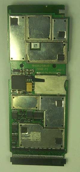
Click to zoom
Application Details
- Equipment Class
- TNB - Licensed Non-Broadcast Station Transmitter
- Date of Grant
- Jan 21, 2002
- Application Purpose
- Original Equipment
- Date of Application
- Sep 26, 2001
- Equipment Note
- iDEN iM1100 Wireless Modem
- Frequency Range
- 806.00000000 - 825.00000000
- Company
- Motorola Solutions, Inc.
- Country
- United States
Documents & Files
Document Text
Text extracted from the exhibit documents filed with the FCC. Open a document above to read the original.
Users Manual
iM1100 Wireless Modem for Windows TM 95, Windows TM 98, Windows 2000, and Windows TM NT User’s Guide www.motorola.com/iden i Table of Contents iM1100 Wireless Modem ...................................................................................1 Setting Up Your Modem ...................................................................................2 Using the Modem ............................................................................................. 12 Getting Status Information ............................................................................. 15 SIM Card Personal Identification Number (PIN) ........................................ 19 Customer Support............................................................................................22 Accessories ........................................................................................................ 23 Safety and General Information.....................................................................24 RF Operational Characteristics .....................................................................24 Portable Radio Product Operation and EME Exposure ............................. 24 Electro Magnetic Interference/Compatibility ...............................................27 Medical Devices ................................................................................................ 27 Operational Warnings ..................................................................................... 29 Operational Cautions ......................................................................................30 Accessory Safety Information ......................................................................... 32 Glossary ........................................................................................................... 34 ii 1 iM1100 Wireless Modem iM1100 WIRELESS MODEM ongratulations on purchasing your Motorola iM1100 wireless modem. Your iM1100 modem offers wireless access to the internet. This wireless modem offers the following features: • Packet Data • Circuit Data/Fax. The iM1100 wireless modem and iDEN Wireless Data Services software provide you with the capability of performing your most important laptop computer activities, like connecting to the internet or corporate intranets, from outside your office or home. Overview The iM1100 wireless modem enables the following data connections: • Packet data: Access the Internet, send and receive e-mail, and transfer small files over the packet data network using standard IP protocols. Packet data transmits packets (blocks) of data at high speed. After the data is transmitted, you can remain connected without being charged for the idle time. Data is sent in bursts. • Circuit data: Send and receive data (faxes, files, etc.) over the circuit- switched cellular channel. C 2 LOGO HERE www.motorola.com/iden SETTING UP YOUR MODEM Installation Requirements To install the Wireless Data Services software onto your laptop, you need the following: • An iM1100 Wireless Modem. • The Wireless Data Services software (provided in your package) • An IBM ® -compatible PC with: - An Intel ® 586 (or higher) processor - Microsoft ® Windows ® 95 installed, Windows ® 98, Windows ® NT, and Windows ® 2000. - Minimum 8 MB of addressable RAM - CD-ROM drive - 9 MB free hard-disk space - Recommended: Mouse or compatible pointing device • Communication software • An account with an iDEN service provider Starting the Software Installation To begin installing the Wireless Data Services software: 1. Turn on your computer and start Windows 95, Windows 98, Windows NT, and Windows 2000. 2. Insert the Wireless Data Services software CD-ROM in your CD- ROM drive. 3. Start the iM1100 wireless modem installation program. 3 Setting Up Your Modem Inserting the iM1100 Wireless Modem After you open the the installation program, this prompt appears: 1. Insert your SIM card into the iM1100 wireless modem as directed in the instructions on the back of the modem. 2. Insert the iM1100 wireless modem into the PCMCIA slot in you laptop. 3. Click OK. Installing on Windows 2000, Windows NT, or Windows 95 and Windows 98 From this point in the installation, the steps you take depend on the operating system running on your laptop: • If you are using Windows 2000, see “Completing the Installation on Windows 2000” on page 3. • If you are using Windows 95 or Windows 98, see “Completing the Installation on Windows 95/Windows 98” on page 5. • If you are using Windows NT, see “Completing the Installation on Windows NT” on page 7. Completing the Installation on Windows 2000 1. Before continuing to install the iM1100 wireless modem software, you must first install an update to Windows 2000. When prompted, click Yes to install the update. Then restart your laptop. 4 LOGO HERE www.motorola.com/iden 2. Click Next when this welcome window appears: 3. When the User Information window appears, enter your name and your company’s name. Then click Next. 4. When the Choose Destination Location window appears, choose a destination location or use the default. Then click Next. 5. In the Select Program Folder window, choose a destination folder, or use the default. Then click Next. 6. To complete the installation, click Finish in the Setup Complete window. After you have competed the installation, make sure that maximum modem speed in set to 19200: 1. From the Start button, choose Accessories > Communications > Network and Dial-up Connections. 2. From the Network and Dial-up Connections window, double click on the iM1100 connection to open it. 3. From the Connecting iM1100 window, click Properties. 4. From the iM1100 window, click Configure. 5. When the Modem Configuration window appears, make sure that the 5 Setting Up Your Modem value shown for Maximum Speed is 19200. If a different value is shown, select 19200 from the drop-down list. Completing the Installation on Windows 95/Windows 98 1. Click Next when this welcome wi…
Text truncated - open the document above for the full version.
Users Manual
This revision contains changes that have occurred since the printing of your iM1100 User’s Guide. This information supersedes the corresponding information in the Safety section of your manual. THIS RADIO PRODUCT MEETS THE GOVERNMENT’S REQUIREMENTS FOR EXPOSURE TO RADIO WAVES. Your wireless radio product is a radio transmitter and receiver. It is designed and manufactured not to exceed the emission limits for exposure to radiofrequency (RF) energy set by the Federal Communications Commission of the U.S. Government. These limits are part of comprehensive guidelines and establish permitted levels of RF energy for the general population. The guidelines are based on standards that were developed by independent scientific organizations through periodic and thorough evaluation of scientific studies. The standards include a substantial safety margin designed to assure the safety of all persons, regardless of age and health. The exposure standard for wireless mobile devices employs a unit of measurement known as the Specific Absorption Rate, or SAR. The SAR limit set by the FCC is 1.6 W/kg. * Tests fo r SAR are conducted using standard operating positions reviewed by the FCC with the device transmitting at its highest certified power level in all tested frequency bands. Although the SAR is determined at the highest certified power level, the actual SAR level of the device while operating can be well below the maximum value. This is because the radio device is designed to operate at multiple power levels so as to use only the power required to reach the network. In general, the closer you are to a wireless base station antenna, the lower the power output. Before a radio product is available for sale to the public, it must be tested and certified to the FCC that is does not exceed the limit established by the government-adopted requirement for safe exposure. The tests are performed in positions and locations as required by the FCC for each model. The highest SAR value for this radio product when tested for use during packet data transmission is 0.55 W/kg. The FCC has granted an Equipment Authorization for this model wireless modem with all reported SAR levels evaluated as in compliance with the FCC RF exposure guidelines. SAR information on this model wireless modem is on file with the FCC and can be found under the Display Grant section of http://www.fcc.gov/oet/fccid after searching on FCC ID AZ489FT5811. Additional information on Specific Absorption Rates (SAR) can be found on the Cellular Telecommunications Industry Association (CTIA) web-site at http://www.wow-com.com. *In the United States and Canada, the SAR limit for wireless modems used by the public is 1.6 watts/kg (W/kg) averaged over one gram of tissue. The standard incorporates a substantial margin of safety to give additional protection for the public and to account for any variations in measurements. Manual Revision iM1100User Guide Operation To maintain FCC RF exposure compliance, position the antenna and the radio product at least one inch (2.5 cm) from any part of the body of the user or bystanders when using the supplied antenna. When using any approved accessory antenna, position it at least eight inches (20 cm) from any part of any person. MOTOROLA, the Stylized M Logo, and all other trademarks indicated as such herein are trademarks of Motorola, Inc. Reg. U.S. Pat. & Tm. Off. ©2002 Motorola All other product or service names are the property of their respective owners. Printed in U.S.A. All Rights Reserved. NNTN4319A @NNTN4319A@
Attestation Statements
FCC Filing Package for Motorola iDEN Type II PC Card Modem FCC ID: AZ489FT5811 iDEN, Motorola Inc., 8000 W. Sunrise Blvd., Plantation, FL 33322, USA WWW.MOT.COM/iDEN Page:2-1 Exhibit 2. Attestation Statement—Pursuant to 47 CFR 2.907 The technical data supplied with this application, having been taken under my supervision is hereby duly certified. The following is a statement of my qualifications: B.S. in Electrical Engineering, 2000, Technological Academic Center, Holon 2 years experience in RF/EMI measurement NAME: Erran Prigat SIGNATURE: Erran Prigat DATE: 9/7/01 POSITION: Electrical Engineer I hereby certify that the above application was prepared under my direction and that to the best of my knowledge and belief, the facts set forth in the application and accompanying technical data are true and correct. NAME: Zami Schwartzman SIGNATURE: Zami Schwartzman DATE: 9/7/01 POSITION: Engineering Section Manager
Cover Letter(s)
Applicant: Motorola Inc FCC ID: AZ489FT5811 www.mot.com/iDEN iDEN, Motorola Inc., 8000 W. Sunrise Blvd., Plantation, FL 33322 Page: 13- 1 26 th September 2001 Authorization & Evaluation Division Federal Communications Commission Laboratory 7435 Oakland Mills Road Columbia, MD 21046 Gentlemen; Motorola Inc., 8000 West Sunrise Boulevard, Fort Lauderdale, Florida 33322, herein submits it’s application for Certification of the transmitter with FCC ID: AZ489FT5811. This variable power (0.221 to 700.0 milliwatt ERP) transmitter is part of a battery powered data transceiver which can be inserted into a PCMCIA peripheral slot commonly found in a notebook personal computer or a personal digital assistant (PDA). This transmitter is used in a SMR and EA SMR trunking system operating in the United States 806-821/851-866 MHz frequency band. This data transceiver is of the receive-first type described in International Telecommunications Union Recommendation ITU-R M.1221 entitled Technical And Operational Requirements For Cellular Multimode Mobile Radio Stations. It must first find, acquire and lock onto a control channel from a predefined set of control channel frequencies assigned to a companion Authorized base station (e.g. – FCC ID: ABZ89FC5792). Transmission is not possible until lock to a base station control channel has been achieved, then transmission is limited to digitally modulated service request bursts on the reverse control channel. Upon recognition of a proper request, the control channel base station transmitter will then assign the transceiver a traffic channel for transmission of digital voice or circuit-switched data from the set of frequencies for which the trunking system is licensed. Attached Exhibit 12.1 provides additional descriptive details. It is expected that this time division multiplexed transceiver marketed in the United States will also be used for itinerant operation with companion Authorized base stations by users requesting trunked radio and telephone interconnect service while roaming outside the United States. In some countries the companion base stations are licensed to operate at frequencies in the 821-825/866- 870 MHz band in addition to some of those in the 806-821/851-856 MHz band normally used in United States SMR systems. Consequently, this transmitter has been designed to meet FCC requirements for operation in the 806-821 MHz band over the more global band of 806 - 825 MHz when used with a companion Authorized Base Station. Thus, performance data is provided to substantiate FCC compliant operation with a Companion Base Station over the broader 806 to 825 MHz band expected for global use of this handheld transceiver. To facilitate global roaming it is kindly requested that a note be provided in the Grant for Equipment Authorization which states that this ‘receive first’ type of equipment is compliant for transmitter operation over the broader range 806-825 MHz when used with a compatible Authorized Base Station. This will aid equipment authorization in foreign countries which accept a United States FCC Grant for Equipment Authorization, yet not jeopardize United States public safety or cellular Applicant: Motorola Inc FCC ID: AZ489FT5811 www.mot.com/iDEN iDEN, Motorola Inc., 8000 W. Sunrise Blvd., Plantation, FL 33322 Page: 13- 2 systems licensed to operate in the 821-825 MHz frequency band since no compatible base station may be authorized on those frequencies in the United States. It is also expected that this transceiver type will be marketed outside the United States and brought into the United States for itinerant “roaming” operation on compatible 806 - 821 MHz base stations located within the United States. Consequently, upon receipt of Authorization, only those units of this equipment type authorized for marketing in countries outside the United States will also bear a label with the specified FCC identifier. In accordance with 47 CFR 2.1093(c) this transmitter may be used in “covered” SMR service so it has been subjected to routine environmental evaluation for RF exposure and found to be compliant with the limits specified in 47 CFR 2.1093(d)(2). The subject transmitter complies with 47 CFR 90.203 of the rules in that the operator cannot directly program transmit frequencies using only the unit's normally accessible external controls. Enclosed is a complete Certification application comprised of 12 Exhibits. Contact me at (954) 723-5793 if you require any additional information. Sincerely, /s/ Mike Ramnath FCC Liaison Email: [email protected]
Cover Letter(s)
Applicant: Motorola Inc. FCC ID: AZ489FT5811 Motorola Inc., 8000 W. Sunrise Blvd., Plantation, FL 33322 Page: 13-2 REQUEST FOR CONFIDENTIALITY 27th September 2001 Authorization & Evaluation Division Federal Communications Commission Laboratory 7435 Oakland Mills Road Columbia, MD 21046 Subject: Application for Type Acceptance of Transmitter with FCC ID: AZ489FT5811. Gentlemen; Motorola is requesting that Exhibit 4 (Circuit Description), Exhibit 5 (Schematic Diagrams), and Exhibit 10 (Semiconductor/Active Device List) not be made routinely available for public inspection. Motorola is in the process of licensing the technology and has a number of Patent applications pending. Please mark Exhibit 4, 5 and 10 as Confidential. Contact me at (954) 723-5793 if you require any additional information. Regards, /s/ Mike Ramnath FCC Liaison Email: [email protected]
Cover Letter(s)
Date: 28 th November 2001 Mr. Stan Lyles Authorization & Evaluation Division Federal Communications Commission Laboratory 7435 Oakland Mills Road Columbia, MD 21046 Re: Form 731 Confirmation Number: EA102585 with FCC ID: AZ489FT5811. Dear Mr. Lyles; Motorola Inc., 8000 West Sunrise Boulevard, Fort Lauderdale, Florida 33322, herein submits its response to the 15 th November 2001 request for information in Correspondence Number 21261. 1) We rate this equipment by maximum RF output power rather than ERP which, from the ERP data, clearly is dependent upon the user’s choice of computing equipment with which it is used. That is our preference for the Grant as well since we cannot guarantee that 0.546 watts will be the maximum when installed in another PDA, or that 0.433 watts will be the maximum when used with another laptop computer. 2) It is recognized that the 824-825 MHz band is outside the extent of part 90. Further, this equipment is precluded from operation in the USA within that band since no base stations have or can be licensed there under part 90. Nonetheless the Commission has issued many grants to include this range (e.g. – FCC ID: AZ489FT5792, AZ489FT5793, AZ489FT5796, AZ489FT5797, AZ489FT5799, AZ489FT5800). The reason is that this product, like the others preceding it, are targeted for sale outside the USA in some countries that permit operation to 825 MHz, and also accept the FCC Grant of Authorization for their transmitter Certification process. For that reason past applications as well as the present application have requested a Grant to 825 MHz. Continuation of the practice to include in the Grant of Authorization operation to 825 MHz will aid that purpose and hence, US trade. 3) The 18K3D7W designator has been previously accepted for numerous predecessor products that employ the same modulation (see examples noted in preceding item 2). The first four characters used (18K3) describe the necessary bandwidth of 18.3 kHz as determined using the calculation method given in Exhibit 6.2. The first symbol, D, was the result of a past discussion with Mr. Frank Coperich of the OET due to similarity of iDEN TDMA with TIA standard TDMA cellular radio equipment authorized under part 22 which uses the same symbol. The second symbol, 7, was chosen because of the multiple digitally modulated subcarriers employed for the emission, as described in Exhibit 4.2. The third symbol, W, was chosen to describe the fact that the emission was used for transmission of multiple types of information; in particular, telephony, 2-way voice, data, and facsimile. 4) The occupied bandwidth is independent of duty cycle, and of the type of modulation used for data transmission (i.e. – QPSK or QAM). As shown in the calculations in Exhibit 6.2, it is determined solely by the spacing of the subcarriers, and the bandwidth of the digital filter used to filter the noise- like spectrum produced by the digital modulation. 5) Our method of rating power (pulse average) results in a power rating that is independent of duty cycle as it rates the power only during information transmission. This rating is used because it is the most effective means to determine link margins and interference potential in RF system analysis and design. Truly the mean power (i.e. – long term or steady state average power) is the product of the pulse average power and the duty cycle. For that reason a duty cycle correction factor is used to determine the pulse average power using an RMS responding measuring instrument such as the HP 438A. This correction is clarified in exhibit 7.1. The mean output power so determined for the 3 duty cycles cited in Exhibit 12.2 of 1:6, 2: 6 and 81:120 is 117 milliwatts, 333 milliwatts and 473 milliwatts respectively. 6) Attached are the dipole test plots requested indicating the actual dates of test. 7) Your input has been noted. Contact me at (954) 723-5793 if you require any additional information. Sincerely, /s/ Mike Ramnath FCC Liaison Email: [email protected] Attachments: Dipole plots (New)
Cover Letter(s)
Date: 7 th December 2001 Mr. Stan Lyles Authorization & Evaluation Division Federal Communications Commission Laboratory 7435 Oakland Mills Road Columbia, MD 21046 Re: Form 731 Confirmation Number: EA102585 with FCC ID: AZ489FT5811. Dear Mr. Lyles; Motorola Inc., 8000 West Sunrise Boulevard, Fort Lauderdale, Florida 33322, herein submits its response to the 30 th November 2001 request for information in Correspondence Number 21389. R1) Attached are new Figures 6-25, 6-26 and 6-27 which are spectrograms like those in Exhibits 6-5 through 6-10. In these new spectrograms the occupied bandwidth marker lines are shown rather than the emission mask limit lines. These spectrograms are time-synchronized (with the transmission burst) measurements for operation at the requested 1:6, 2:6 and 81:120 TDM duty cycles, respectively. At the bottom of each figure the analyzer display shows the bandwidth between the markers. The occupied bandwidths so measured are 17, 498, 17, 455 and 17, 451 respectively and confirm that the emission do not exceed the bandwidth represented by the emission designator. R2.) The reported duty cycle of 67.5% represents signals that pulse between 0% and 100% power levels. With this signaling characteristic it is a valid approach to calculate crest factor using the formula C.F. = 1/D.C. This method of calculating crest factor does not contradict the statement made on page 46 of 66 in the DASY3 user manual because therein SPEAG is referring to signal levels that pulse between 50% and 100%. An email from Neils Kuster of SPEAG included herein confirms the validity of the reported crest factor of 1.5. “Your approach was correct, i.e., a crest factor of 1.5 is ok. Problems occur if the pulses have different amplitudes. In these cases, the linearization becomes more complicated. I hope this clarifies the statement in the manual”. Contact me at (954) 723-5793 if you require any additional information. Regards, /s/ Mike Ramnath FCC Liaison Email: [email protected] Attachments: Figure 6-25 Figure 6-26 Figure 6-27
External Photos
FCC Filing Package for Motorola iDEN Type II PC Card Modem FCC ID: AZ489FT5811 IDEN, Motorola Inc., 8000 W. Sunrise Blvd., Plantation, FL 33322, USA WWW.MOT.COM/iDEN Page: 3- 1 Exhibit 3. External Photographs -- Pursuant to 47 CFR 2.1033(c)12 Photograph 3-1: Top View of modem, antenna retracted. Photograph 3-2: Top View of modem, antenna extended. FCC Filing Package for Motorola iDEN Type II PC Card Modem FCC ID: AZ489FT5811 IDEN, Motorola Inc., 8000 W. Sunrise Blvd., Plantation, FL 33322, USA WWW.MOT.COM/iDEN Page: 3- 2 Photograph 3-3: Side View of modem, antenna extended. Photograph 3-4: Rear view of modem with battery,antenna extended. FCC Filing Package for Motorola iDEN Type II PC Card Modem FCC ID: AZ489FT5811 IDEN, Motorola Inc., 8000 W. Sunrise Blvd., Plantation, FL 33322, USA WWW.MOT.COM/iDEN Page: 3- 3 Photograph 3-5: Close up of the FCC label. Photograph 3-6: Modem in Laptop computer. Photograph 3-7: Modem in PDA.
ID Label/Location Info
FCC Filing Package for Motorola iCARD Type II PC Card Modem FCC ID: AZ489FT5811 IDEN, Motorola Inc., 8000 W. Sunrise Blvd., Plantation, FL 33322, USA WWW.MOT.COM/iDEN Page: 1- 1 Exhibit 1. Identification Label -- Pursuant to 47 CFR 2.925, 2.1065 and 2.1033(c) 11 1.1. Location Back side of the transceiver unit chassis. (See the attached photograph 3.5 in exhibit 3) 1.2. Type The label is a white polyester film laminate with a pressure sensitive adhesive backing. The adhesive is a permanent type acrylic with a minimum peel strength of 5 lbs/in. 1.3. Markings (Text) Enlarged view of label (showing FCC ID and manufacturer type number): FCC Filing Package for Motorola iCARD Type II PC Card Modem FCC ID: AZ489FT5811 IDEN, Motorola Inc., 8000 W. Sunrise Blvd., Plantation, FL 33322, USA WWW.MOT.COM/iDEN Page: 1- 2 Exhibit 1A. General Information 1A.1. Production Plans Quantity production is planned. 1A.2. Application References -- Pursuant to 47 CFR 2.948 and 2.1061 Reference is made to the following Motorola "Application References" Hermon Labs, located in Binyamina Israel is listed with FCC and Industry Canada as follows: 1. FCC OATS registration number is: 90623 2. FCC Anechoic chamber registration number is: 13040/SIT 1300F2 3. Industry Canada OATS registration number is: IC 2186-1 4. Industry Canada anechoic chamber registration number is: IC 2186-2 5. Accredited by A2LA. 1A.3. Data Submittal Procedure Data located in Exhibit 6 is supplied in accordance with Part 2, Sub-part J and Part 90, Sub-part I and Sub-part S of the Commission’s Rules. 1A.4. Similar, currently Type Accepted Transmitter FCC ID: AZ489FT5799
Internal Photos
FCC Filing Package for Motorola iDEN Type II PC Card Modem FCC ID: AZ489FT5811 IDEN, Motorola Inc., 8000 W. Sunrise Blvd., Plantation, FL 33322, USA WWW.MOT.COM/iDEN Page: 9- 1 Exhibit 9. Internal Photographs -- Pursuant to 47 CFR 2.1033(c)12 Photograph 9-1: Front side of modem main board. Photograph 9-2: Front side of modem main board with shields removed. FCC Filing Package for Motorola iDEN Type II PC Card Modem FCC ID: AZ489FT5811 IDEN, Motorola Inc., 8000 W. Sunrise Blvd., Plantation, FL 33322, USA WWW.MOT.COM/iDEN Page: 9- 2 Photograph 9-3: Back side of modem main board. Photograph 9-4: Back side of modem main board with shields removed.
Operational Description
FCC Filing Package for Motorola iDEN Type II PC Card Modem FCC ID: AZ489FT5811 iDEN, Motorola Inc., 8000 Sunrise Blvd., Plantation, FL 33322, USA WWW.MOT.COM/iDEN Page: 12- 1 Exhibit 12. Transmitter Description ----- 47 CFR 2.1033 (c) 4,5,6,7,8 12.1 Transmitter Technical Characteristics This Type II PC Card iDEN Modem transceiver is of the receive first type, meaning it must first find, acquire and lock onto a control channel from a predefined set of control channel frequencies assigned to a compatible base station. Transmission is not possible until acquisition and lock has been achieved, then it is limited to transmission of service request bursts on the digitally modulated reverse control channel. Upon recognition of a proper request, the control channel base station transmitter will then assign the transceiver a traffic channel for transmission of circuit-switched data or packet-switched data from the set of frequencies for which the trunking system is licensed. The technical capability of the transceiver complies with FCC emissions requirements for the 806 - 821 MHz range for which companion base stations are authorized in the United States. It is expected that this Type II PC Card iDEN Modem transceiver marketed in the United States will also be used for itinerant roaming operation outside the United States with companion base stations that may operate anywhere within the broader frequency range 806 - 825 MHz. It is also expected that this transceiver type will be marketed outside the United States and brought into the United States for itinerant “roaming” operation on compatible 806 - 821 MHz base stations located in the United States. Thus performance data is provided to substantiate FCC compliant operation with a companion base station over the broader international 806 to 825 MHz band expected in use of this handheld transceiver outside the United States. In addition to controlling the assigned frequency to which the transceiver will be slaved, the compatible base station frequency serves as an accurate, stable reference for the transceiver local reference oscillator by virtue of a transceiver AFC function inherent in the acquisition and lock process. The trunking system protocol uses a 90ms frame divided into six 15ms time slots. The base station allocates the number of 15ms time division multiplex (TDM) time slots in which the transceiver transmits, depending on the user requested transmission mode. These slot allocations are summarized in Table 12-1. FCC Filing Package for Motorola iDEN Type II PC Card Modem FCC ID: AZ489FT5811 iDEN, Motorola Inc., 8000 Sunrise Blvd., Plantation, FL 33322, USA WWW.MOT.COM/iDEN Page: 12- 2 Table 12-1: TDM Time Slot Allocation Transmission Service Mode Transmission Time Slots Allocated per Six-Slot Frames 1) Circuit-Switched Data* 1 (duty cycle=16.67%) or 2 (duty cycle=33.33%) (base station preset) 2) Packet-Switched Data* # up to 81 out of 120 contiguous slots (duty cycle=67.5% max) * Via a PCMCIA port at an input rate of 115,200 bps maximum for circuit-switched data and for packet-switched data. In addition to controlling the assigned frequency to which the transceiver will be slaved, the compatible base station frequency serves as an accurate, stable reference for the transceiver local reference oscillator by virtue of a transceiver AFC function inherent in the acquisition and lock process. The RF output power of the transceiver also is dynamically controlled by the radio which senses the received signal strength and adjusts transmitter output power in approximately 1dB steps over the range from rated power to 34 dB cutback. A. Output Power 0.221 to 700 milliWatts (Pulse average) B. Maximum Antenna Gain -1.0 dBd C. Maximum ERP 546 milliWatts (Pulse average) D. Frequency Range 806-825 MHz** E. Frequency Stability ≤ 1.9 PPM * F. Emission Designator 18K3D7W G. Spurious Emissions < -13 dBm H. Maximum DC Voltage and 4.1 V in transmit slot # Current into the final RF 0.85 A in transmit slot # amplifier stage (at nominal battery voltage) ** See Exhibit 12.1 * See Exhibit 6.6 # See Exhibit 6.1 FCC Filing Package for Motorola iDEN Type II PC Card Modem FCC ID: AZ489FT5811 iDEN, Motorola Inc., 8000 Sunrise Blvd., Plantation, FL 33322, USA WWW.MOT.COM/iDEN Page: 12- 3 12.2. Transmitter Application The following features, options, and accessories characterize the modem . 12.2.1. Battery Available: 12.2.1.1. Lithium Ion (Li), 470mAh, Kit No. NNTN4051A 12.2.2. Chargers Available: 12.2.2.1. Rapid Travel Charger, AC line powered, Kit No. SPN4716 12.2.2.2 Vehicular Power Adapter, Kit No. SYN7818 12.2.3. Antennas Available: 12.2.3.1. Standard, Monopole whip antenna Kit No. FAF5055A 12.2.3.2. Optional, Roof Mount antenna Kit No. HA…
Text truncated - open the document above for the full version.
Contact Information
Applicant
Deanna Zakharia(Regulatory Compliance Manager)
Technical Contact
Motorola IncMike Ramnath
[email protected]954-723-5793
8000 West Sunrise Blvd · Ft. Lauderdale, Florida · United States
Technical Specifications
| # | Rule Parts | Frequency Range | Power Output | Emission | Tolerance |
|---|---|---|---|---|---|
| 1 | 90.691 | 806 MHz - 825 MHz | 700.00 mW | 18K3D7W | 1.9000000000 ppm |
Other Applications from Motorola Solutions, Inc.

AZ489FT4980
Sep 08, 2026Portable two way radio
Equipment Class
TNF - Licensed Non-Broadcast Transmitter Held to FaceAZ489FT4981
Aug 14, 2026Handheld Portable - TANAPA BPR 45 400-470 MHZ 4W NKP
Equipment Class
TNF - Licensed Non-Broadcast Transmitter Held to Face
AZ489FT7187
Jul 13, 2026Portable 2-Way Radio with Bluetooth, Bluetooth LE, WIFI 2.4GHz, WIFI 5GHz, LTE
Equipment Class
DSS - Part 15 Spread Spectrum TransmitterAZ499FT6031
May 11, 2026Operation Critical Wireless Earpiece PTT
Equipment Class
DSS - Part 15 Spread Spectrum Transmitter
AZ499FT5879
Dec 19, 20252-way Portable Radio with BT, BTLE, WIFI, NFC and LTE
Equipment Class
DSS - Part 15 Spread Spectrum Transmitter